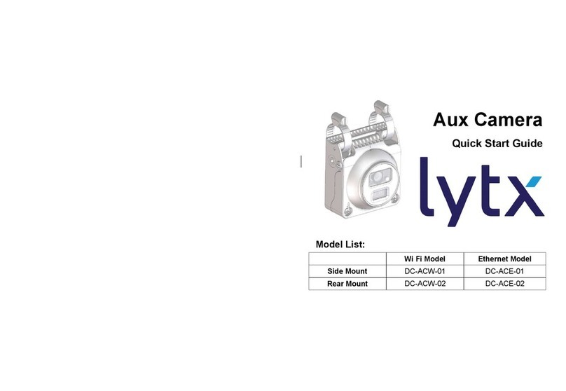
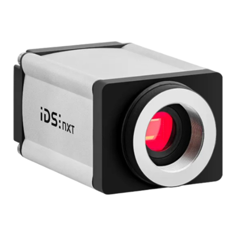
StoneAge CAM-UNI User manual

CAM-UNI
Universal
Camera
User Guide
PL 698 Rev A
(12/2020)

T
A
B
L
E
O
F
C
O
N
T
E
N
T
S
MANUFACTURER’S INFORMATION ...........................................................3
SYSTEM REQUIREMENTS ................................................................3
KEY FEATURES ..........................................................................3
DESCRIPTION OF EQUIPMENT AND INTENDED USE .......................................3
EC DECLARATION OF INCORPORATION ...................................................5
WARNING AND SAFETY INSTRUCTIONS .....................................................6
OPERATOR TRAINING .....................................................................6
PERSONAL PROTECTIVE EQUIPMENT REQUIREMENTS ...................................7
PRODUCT OVERVIEW .........................................................................8
UNIVERSAL CAMERA PACKAGE CONTENTS...............................................8
UNIVERSAL CAMERA PACKAGE SHOWN ON CB-ABX AND CBX-ABX CONTROL BOXES...9
UNIVERSAL CAMERA PACKAGE SHOWN ON PEDESTAL STYLE CONTROL BOX ...........10
UNIVERSAL CAMERA MOUNTING OPTIONS ...............................................11
INSTALLATION .................................................................................12
CAMERA SYSTEM HOOK UP TO PEDESTAL STYLE STONEAGE CONTROL BOXES ..........12-13
CAMERA SYSTEM HOOK UP TO CB-ABX OR CBX-ABX STONEAGE CONTROL BOXES......14-15
TROUBLESHOOTING..........................................................................16
PART DIAGRAMS...............................................................................17-27
TERMS AND CONDITIONS AND WARRANTY .................................................28-31
2

M
A
N
U
F
A
C
T
U
R
E
R
S
I
N
F
O
R
M
A
T
I
O
N
StoneAge Inc.
466 S. Skylane Drive
Durango, CO 81303, USA
Phone: 970-259-2869
Toll Free: 866-795-1586
www.stoneagetools.com
StoneAge NL
Reedijk 7Q
3274 KE Heinenoord
Netherlands
(+31) (0) 85 902 73 70
This manual must be used in accordance with all applicable national laws. The manual shall be regarded as
a part of the machine and shall be kept for reference until the nal dismantling of the machine, as dened by
applicable national law(s).
Updated manuals can be downloaded at:
https://www.stoneagetools.com/manuals
DESCRIPTION OF EQUIPMENT AND INTENDED USE
The Universal Camera system is a product designed that removes the worker(s) from the work area. Despite the
remote operation of the equipment, the operator will need to see with detail the work area. The camera will be
required for the operator to align ex lances with tube opening as well as monitor the area for any hazards that
could damage the cleaning equipment or the equipment being cleaned. When automatic indexing technology is
applied to the various ex lance cleaning equipment, it will still be necessary to have a visual of the work area for
operation and safety monitoring.
KEY FEATURES
• The camera system has the ability to support multiple cameras with a switchable monitor to collect
real-time imagery.
• The camera system does not have recording capability, WIFI, or Bluetooth, it is only intended for real-time
imagery.
• The camera system is intended to be used with all StoneAge automated equipment.
SYSTEM REQUIREMENTS
Power Pack input power 100-240V AC, 1.8A.
3

4

D
E
C
L
A
R
A
T
.
I
O
N
O
F
C
O
N
F
O
M
I
T
Y
EC DECLARATION OF CONFORMITY
Manufacturer: StoneAge Incorporated
466 South Skylane Drive
Durango, CO 81303
USA
Authorized Representative: StoneAge Netherlands BV
Reedijk 7Q
3274 KE Heinenoord
Netherlands
Bob Van Wordragen, Operations Manager StoneAge NL
Declare that: Universal Camera System (CAM-UNI)
is a video device designed to be used with multiple types of waterblasting systems.
Is compliant with the following Directives and Standards:
EN/IEC 62368-1 CB project- Product Safety testing standard for “Information Technology Equipment” & Audio Video Equipment
EU - RoHS Directive (2011/65/EU)
FCC 15B - Unintentional Radiators
ICES-003 Class A- Limits radio noise for non-residential operation
EN 55024 Class A - European immunity requirements for information technology equipment
EN 55032- Electromagnetic compatibility of multimedia equipment - Emission requirements
EN 55035- Electromagnetic Compatibility of Multimedia Equipment - Information Technology Equipment
EN 61000-3-2 Harmonics Current Emission, EN 61000-3-3 Voltage Fluctuation Flicker, EN 61000-4-2 ESD, EN 61000-4-3 RF Immunity, EN 61000-4-4 EFT,
EN 61000-4-5 Surge, EN 61000-4-6 Conducted RF Immunity, EN 61000-4-8 Magnetic Field, EN 61000-4-11 Voltage Dips and Interruption
The Technical File for Universal Camera System (CAM-UNI) is maintained at:
StoneAge Incorporated, 466 South Skylane Drive, Durango, CO 81303, USA and was compiled by the Engineering Manager. The Technical File is
available through the Authorized Representative. This Declaration of Conformity is issued under the exclusive responsibility of StoneAge Incorporated.
________________________________________ 12/15/20
StoneAge Incorporated, Durango, CO, USA Date
Adam Markham, Director of Engineering and Technology
5

W
A
R
N
I
N
G
&
S
A
F
E
T
Y
I
N
S
T
R
U
C
T
.
I
O
N
S
StoneAge has designed and manufactured this
equipment considering all hazards associated with
its operation. StoneAge assessed these risks and
incorporated safety features in the design. StoneAge
WILL NOT accept responsibility for the results of misuse.
IT IS THE RESPONSIBILITY OF THE INSTALLER/
OPERATOR to conduct a job specic risk assessment
prior to use. Job specic risk assessment MUST be
repeated for each different set up, material, and location.
The risk assessment MUST conform to the Health and
Safety at Work Act 1974 and other relevant Health and
Safety legislation.
The risk assessment MUST consider potential material or
substance hazards including:
• Aerosols
• Biological and microbiological (viral or bacterial)
agents
• Combustible materials
• Dusts
• Explosion
• Fibers
• Flammable substances
• Fluids
• Fumes
• Gases
• Mists
• Oxidizing Agents
OPERATOR TRAINING
Managers, Supervisors, and Operators MUST be trained
in Health and Safety Awareness of High-pressure Water
Jetting and hold a copy the Water Jetting Association
(WJA) Code of Practice, or equivalent (see www.
waterjetting.org.uk).
Operators MUST be trained to identify and understand
all applicable standards for the equipment supplied.
Operators should be trained in manual handling
techniques to prevent bodily injury.
Operators MUST read, understand, and follow the
Operational and Training Requirements (Section 7.0) of
WJTA-IMCA’s Recommended Practices For The Use Of
High-pressure Waterjetting Equipment, or equivalent.
Operators MUST read, understand and follow the
Warnings, Safety Information, Assembly, Installation,
Connection, Operation, Transport, Handling, Storage,
and Maintenance Instructions detailed in this manual.
6

W
A
R
N
I
N
G
&
S
A
F
E
T
Y
I
N
S
T
R
U
C
T
.
I
O
N
S
WARNING
Operations with this equipment can be potentially hazardous. Caution MUST be exercised prior to and during
equipment and water jet tool use. Please read and follow all of these instructions, in addition to the guidelines in the
WJTA Recommended Practices handbook, available online at www.wjta.org. Deviating from safety instructions and
recommended practices can lead to severe injury and/or death.
Refer to WJTA-IMCA’s, Recommended Practices For The Use Of High-pressure Waterjetting Equipment and/or The
Water Jetting Association’s, WJA Code of Practice for additional safety information.
PERSONAL PROTECTIVE EQUIPMENT
REQUIREMENTS
Use of Personal Protective Equipment (PPE) is dependent
on the working pressure of water and the cleaning
application. Managers, Supervisors, and Operators MUST
carry out a job specic risk assessment to dene the
exact requirements for PPE. See Protective Equipment
for Personnel (Section 6) of WJTA-IMCA’s Recommended
Practices For The Use Of High-pressure Waterjetting
Equipment for additional information.
Hygiene - Operators are advised to wash thoroughly
after all waterjetting operations to remove any waterblast
residue which may contain traces of harmful substances.
First aid provision - users MUST be provided with suitable
rst aid facilities at the operation site.
PPE may include:
• Eye protection: Full face visor
• Foot protection: Kevlar® brand or steel toe capped,
waterproof, non-slip safety boots
• Hand protection: Waterproof gloves
• Ear protection: Ear protection for a minimum of 85
dBA
• Head protection: Hard hat that accepts a full face
visor and ear protection
• Body protection: Multi-layer waterproof clothing
approved for waterjetting
• Hose protection: Hose shroud
• Respiratory protection: May be required; refer to job
specic risk assessment
7

P
R
O
D
U
C
T
O
V
E
R
V
.
I
E
W
UNIVERSAL CAMERA (CAM-UNI-PKG)
UNIVERSAL CAMERA PACKAGE CONTENTS
Power Pack
Assembly
Ball Grip
Positioning Assembly
Camera Case
Monitor Assembly
and Hardware
Camera
Assembly
Camera
Bracket
Cable Tie
1m and 10m
Camera Cables US or EU Power
Connector
Pedestal
Monitor Mount
8

P
R
O
D
U
C
T
O
V
E
R
V
.
I
E
W
UNIVERSAL CAMERA PACKAGE CONTENTS
SHOWN ON CB-ABX AND CBX-ABX STYLE CONTROL BOX
US or EU Power
Connector
Power Pack
Assembly
Monitor Assembly
and Hardware
Camera
Assembly on
Camera Cable
CB-ABX or CBX-ABX
Control Box Monitor Mount
9

P
R
O
D
U
C
T
O
V
E
R
V
.
I
E
W
UNIVERSAL CAMERA PACKAGE CONTENTS
SHOWN ON A PEDESTAL STYLE CONTROL BOX
Power Pack
Assembly
Pedestal Style
Control Box
Monitor Assembly
and Hardware
Camera
Assembly on
Camera Cable
US or EU Power
Connector
Monitor Mount
10

P
R
O
D
U
C
T
O
V
E
R
V
.
I
E
W
UNIVERSAL CAMERA MOUNTING OPTIONS
SHOWN WITH THE BALL GRIP POSITIONING ASSEMBLY
Ball Grip
Positioning
Assembly
Camera
Assembly
Camera
Bracket
Mounted to a Striker Arm
Mounted to Positioner
Air Motor
Mounted to an ABX
Hose Guide
Mounted to an ABX
Tractor Handle
11

I
N
S
T
A
L
L
A
T
I
O
N
CAMERA SYSTEM HOOK UP TO PEDESTAL STYLE STONEAGE CONTROL BOXES
1. Attach the Monitor to the Monitor Mount Assembly with the supplied screws, washers, and wing nuts as shown
in the gure below. Tighten by hand.
2. Loosen the thumb screws on the Controller box and Monitor Mount. Remove the Controller Box from the stand
and slide the Monitor Mount onto the Stand. Return the Controller Box to the Stand and tighten the Thumb
Screw. The Monitor Mount collar should sit just under the Controller Box Collar.
3. Hang the Power Pack by the handle from the Monitor Mount.
Monitor Mount
Assembly
Monitor
Assembly
Power
Pack
Stand
Thumb
Screws
Controller
Box
12

4. Plug the cable coming from the Monitor into the “OUTPUT” port.
5. Plug the female end of the Camera Cable into the “INPUT 1” port on the side of the Power Pack.
(INPUT 2 would be for an additional camera.)
6. Screw the Camera onto the male end of the Camera Cable. The Camera can be mounted in a variety of
ways. (See StoneAge user manuals for the correct mounting procedures related to StoneAge equipment.)
7. Plug the US or EU power cable connector into the opposite side of the Power Pack.
8. Plug the unit into the appropriate outlet.
9. Press the ON/OFF button to power the unit on.
Output Port
(Monitor Cable)
Power
ON/OFF
Input 1 Port
(Camera Cable)
US or EU style
Power Cable
Connector
Camera
Cable
Camera
Input 1 Port
on Power Pack
Female end of
Camera Cable
I
N
S
T
A
L
L
A
T
I
O
N
13

CAMERA SYSTEM HOOK UP TO CB-ABX OR CBX-ABX STYLE STONEAGE CONTROL BOXES
1. Remove the two Torx screws from the back of the Control Box.
2. Position the CAM 603-C Bracket as shown and attach with the two Torx Screws previously removed from the
Control Box.
3. Fasten the Monitor to the Bracket with the included fasteners. Secure with the wing nuts as shown.
Monitor
CAM 603-C
Bracket
I
N
S
T
A
L
L
A
T
I
O
N
14

I
N
S
T
A
L
L
A
T
I
O
N
4. The Power Pack can be set on the ground.
5. Plug the cable coming from the Monitor into the “OUTPUT” port.
6. Plug the male end of the Camera Cable into the “INPUT 1” port on the side of the Power Pack.
(INPUT 2 would be for an additional camera.)
7. Screw the Camera onto the female end of the Camera Cable. The Camera can be mounted in a variety of
ways. (See StoneAge user manuals for the correct mounting procedures related to StoneAge equipment.)
8. Plug the US or EU power cable connector into the opposite side of the Power Pack and the other end into
the appropriate outlet.
9. Press the ON/OFF button to power the unit on.
US or EU style
Power Cable
Connector
Output Port
(Monitor Cable)
Power Pack Power
ON/OFF
Input 1 Port
(Male end of
Camera Cable)
Female end of
Camera Cable
Camera
15

T
R
O
U
B
L
E
S
H
O
O
T
.
I
N
G
TROUBLESHOOTING
1. Each label has an indicator light next to it, as shown below.
2. When the indicator light turns red, it means the cable and/or equipment on that port has a fault and is damaged
and requires replacement.
16
Indicator
Light

# PART NUMBER QTY
1 CAM 327-??? POWER CONNECTOR ASSEMBLY 1
2 CAM 603-P PEDESTAL MONITOR MOUNT 1
3 CAM-UNI UNIVERSAL CAMERA SYSTEM 1
UNIVERSAL CAMERA (CAM-UNI-PKG)
UNIVERSAL CAMERA PACKAGE
P
A
R
T
D
I
A
G
R
A
M
S
P
A
R
T
D
I
A
G
R
A
M
S
17

UNIVERSAL CAMERA (CAM 327-??)
POWER CONNECTOR ASSEMBLY US OR EU
#-US PART NUMBERS QTY
1 CAM 217-002 AC CORD PIGTAIL 1
2CAM 320.1 CIRCULAR CONNECTOR 2 PIN 1
#-EU PART NUMBERS QTY
1 CAM 298-001 AC EUROPEAN PLUG 1
2CAM 320.1 CIRCULAR CONNECTOR 2 PIN 1
P
A
R
T
D
I
A
G
R
A
M
S
18

P
A
R
T
D
I
A
G
R
A
M
S
UNIVERSAL CAMERA (CAM 603-X)
PEDESTAL MONITOR MOUNT
# PART NUMBER CAM 603-C CAM 603-P
1 CAM 149 10-24 WING NUT 2 -
2 CAM 331 CBX MONITOR MOUNT 1 -
3 CB 488 MONITOR MOUNT ASSY - 1
4 GS 319-02 SHCS 10-24 x .50 SS 2 -
5 GW 319-F WASHER, FLAT #10 SS 2 -
6 PROP 440-24 CAMERA MOUNT ASSY FOR DBP - 1 19

UNIVERSAL CAMERA (CB 488)
MONITOR MOUNT ASSEMBLY
# PART NUMBER QTY
1 CAM 149 10-24 WING NUT 2
2 CB 489 MONITOR BRACKET 1
3 CB 724 MODIFIED COLLAR 1
4 CB 725 THREAD LOCKING SLOTTED INSERT,
1/4-20 X 3/8-16
1
5 CB 726 THREE LOBE KNOB, .25-20 1
6 GN 319-L-32 NUT, NYLOK 10-32 SS 1
7 GS 319-02 SHCS 10-24 X .50 SS 2
8 GS 319-02-32 SHCS 10-32 X .50 SS 4
9 GW 319-F WASHER, FLAT #10 SS 2
P
A
R
T
D
I
A
G
R
A
M
S
20
Table of contents
