StonePoint 1G1200M-PB User manual
1
Revision102715
Motion Activated 1200 Lumen
LED Security Light
Model: 1G1200M-PB/1G1200M-PW
Please read all instructions thoroughly and carefully prior to installing this product.
Retain these instructions for future reference.
Failure to follow these instructions could result in voiding the product warranty.
Keystone Group assumes no liability or responsibility for claims arising from improper installation or improper use.
For questions in regard to warranty of this product contact us at 855.652.6164, Monday through Friday, 7:00am to 4:00pm MST
READ FIRST: IMPORTANT SAFETY INSTRUCTIONS
Before you begin installing, servicing, or maintenance of this product, follow these general precautions.
•To reduce the risk of death, personal injury or property damage from fire, electric shock, falling parts, cuts/abrasions and
other hazards please read all warnings and instructions included with and on this product prior to installation.
•For commercial installation: service and maintenance of this product should be performed by a qualified, licensed
electrician.
•For residential installation: If you are unsure about the installation or maintenance of this product, consult a qualified
licensed electrician.
•Do not mount the unit against flammable surfaces.
•This product is intended to be used outdoors, and be subject to the elements; such as rain and snow and we recommend it
to be mounted at least 6’ 6” off the ground
•This LED product must be powered directly to a switched circuit.
•This product should not be used in areas with limited ventilation or high ambient temperatures.
•This product CANNOT be used with a dimmer switch, motion or occupancy sensor or other electronic switching device.
•This product is intended to be connected to a properly installed and grounded UL listed junction box.
WARNING: RISK OF ELECTRICAL SHOCK
•Turn off electrical power at fuse or circuit breaker box before wiring product to the power supply.
•Verify voltage is 110-240V before installing.
•Make all electrical and grounded connections in accordance with the National Electric Code and any applicable local code
requirements.
•All wiring connections should be capped with UL listed wire connectors.
CAUTION: RISK OF PRODUCT DAMAGE
•Never connect fixture with power on.
•Do not mount or support product in a manner that can cut the outer wire jacket or damage the wire insulation.
•Avoid covering LED products with insulation, foam, or other materials that will prevent convection or conduction cooling.
•Never connect an LED product directly to dimmer packs, occupancy sensors, timing devices, or other related control devices,
unless individual product specifications deem otherwise.
2
Revision102715
•LED products are polarity sensitive, ensure proper polarity before installation.
•Electrostatic Discharge (ESD) can cause damage to LED products. Wear personal grounding equipment during
installation and service of the product.
•Do not touch the individual electronic components, it may cause ESD (Electronic Discharge), shorten lamp life or alter
performance.
CAUTION: RISK OF INJURY
•Avoid direct eye exposure to the light source while it is on.
•LED LIGHTS ARE EXTREMELY BRIGHT, UNDER NO CIRCUMSTANCES SHOULD YOU LOOK DIRECTLY INTO AN LED LIGHT, THIS
MAY CAUSE IRREPARABLE DAMAGE TO THE EYES.
•Please dispose of packaging materials and account for all small parts as these can be hazardous to small children.
WARNING: RISK OF BURN
•Allow fixture to cool completely before handling.
•Do not exceed maximum voltage marked on the label.
•Keep combustible and other materials that can burn away from the light, lamp, and lens.
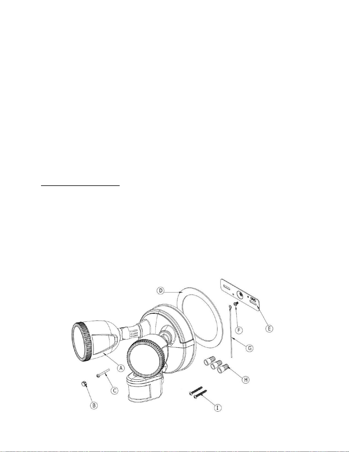
Installation Instructions
Part
Description
Quantity
A
Light Fixture
1
B
Plastic Screw Cover
1
C
Stainless Steel Screw
1
D
Gasket (optional)
1
E
Cross Bar
1
F
Grounding Screw
1
G
Grounding Wire
1
H
Wire Nut
3
I
Stainless Steel Mounting Screws
2
Silicon Sealant recommended (not included)
Tools Required for Installation:
Phillips screwdriver, level
3
Revision102715
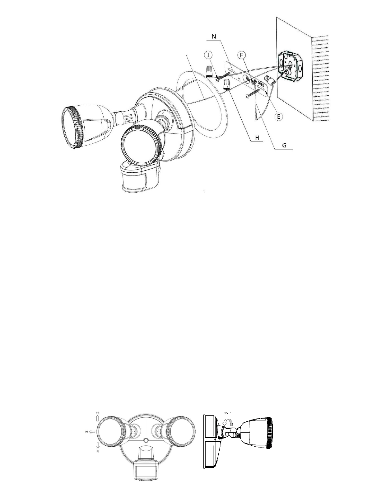
MOUNTING AND WIRING THE LIGHT
NOTE: DO NOT MOUNT ON THE GROUND, RECOMMENDED INSTALLATION HEIGHT IS 6 ½ FEET TO 10 FEET
** Before you begin make sure that your power is turned off at your circuit breaker box **
**Do not rely on the switch power being turned off **
1. Install the cross bar (E) to the junction box and secure with the (2) mounting screws (I). If installing to a wall or
building, pre-drill holes and use appropriate plugs/anchors, once your holes are drilled you can install the cross bar to
the surface using the two mounting screws (I).
2. On the cross bar locate GND, attach the ground wire (G) with the grounding Screw (F) to the cross bar.
3. Use a wire nut (H) to connect the ground wire (G) to the house ground wire (typically copper). For proper connection,
place wire nut over wires and twist clockwise until tight.
4. Connect supply wires with wire nuts (H) as shown in the figure above.
Black supply wire connects to the Black power supply wire (Live)
White product wire connects to the White supply wire (Neutral)
5. You may use the optional gasket (D) at this time.
6. Install the light fixture (A) to the cross bar (E). Use silicon sealant (not included) around the perimeter of the light to
seal for moisture.
7. Screw in the stainless steel screw (C) to hold fixture in place. Insert plastic screw cover (B) into screw hole.
8. Turn on your electricity after the install has been completed.
9. Turn on power switch. (If power switch is not on, the light will not cycle on or off)
ADJUSTING YOUR LIGHT HEADS
Your light heads can be adjusted by turning the individual light head to desired position. You can also adjust your light head up
and down to your desired position.

4
Revision102715
SETTING THE MOTION SENSOR
Detection Range: 50’
Detection Angle: 180°
SENSOR ADJUSTMENTS
** You must adjust the motion sensor on the light to the desired area before you can adjust the time
and LUX settings**
TIME SETTING
This setting controls the time span of how long your security light will remain on. The time setting will
allow you to set the time period the light will stay on. Slide the switch to the amount of time you would
like the light to stay on. (See illustration, dials are located on the bottom side of the motion detector).
LUX SETTINGS
The LUX settings controls when the light will come on; it controls the amount of light needed to turn the
light on. The LUX settings are marked on the bottom side of the motion sensor. Use one of the three
predetermined settings as illustrated. To adjust the light to come on when it is darker outside slide the
switch to “Night”; to adjust the light to come on at dusk slide the switch to “Dusk”. To adjust the light
to come on when it is lighter outside slide the switch to the “Day”.
5
Revision102715
PRODUCT SPECIFICATIONS
•Detection Method: PIR (Passive Infrared)
•Detection Range: Maximum 50ft
•Detection Angle: 180°
•LED Angle: 120°
•Time Adjustment: (minimum) 5 seconds to (maximum) 12 minutes
•Operating Voltage: 110 –240 volts
•IP Rating: 44
•Warm Up: 50+/-15 seconds
TROUBLE SHOOTING
Problem
Possible Cause
Possible Correction
Light does not come on
1. No power to the fixture
2. Fixture is sensing too much
light
1. Confirm wall switch is on
2. Cover photocell, unit should
come on. Unit may need to be
relocated.
Light stays on
1. Area is too shaded
1. Adjust the LUX setting
Light does not detect motion
1. The sensor may not be aimed
correctly
1. Adjust the LUX setting
PRODUCT MAINTENANCE
To clean the surface of the light, use mild soap and water.
Do not use scouring pads, powders, steel wool or any other abrasive materials. Do not immerse in water.
For any further questions please contact us at 855.652.6164, Monday through Friday, 7am to 4pm Mountain Standard Time.
PRODUCT WARRANTY
Keystone Group will cover any manufacturing defect for a period of three (3) years from the date of purchase with original proof of purchase.
Keystone Group will either repair or replace your product at our discretion. The warranty is not transferable and is only valid to the original
purchaser. This warranty does not apply to the following; acts of God, product that has been modified, opened, disassembled or unauthorized
repair, products not used in accordance with the provided instructions, damages caused by shipping, improper handling, accident or misuse.
The finish of any part of the product, scratches, weathering, corrosion, discoloration, fading, these are all considered normal wear and tear.
This warranty does not cover any damages of merchandise in transit, any damages need to be reported to the carrier and a claim needs to be
filed with the carrier.
FCC Information
This device complies with Part 15 of the FCC Rules. Operation is subject to the following 2 conditions: (1) This device may not cause harmful
interference, and (2) This device must accept any interference received, including interference that may cause undesired operation. Warning:
Changes or modification to this unit not expressly approved by the party responsible for compliance could void the user’s authority to operate
the equipment. NOTE: This equipment has been tested and found to comply with the limited Class B digital service, pursuant to Part 15 of the
FCC Rules. Their limits are designed to provide reasonable protection against harmful interference in a residential installation. This equipment
generates uses and can radiate radio frequency energy and, if not installed and used in accordance with the instructions, may cause harmful
interference to radio communications. However, there is no guarantee that interference will not occur in a particular installation. If the
equipment does cause harmful interference to radio or television reception, which can be determined by turning the equipment off and on; the
user is encouraged to try to correct the interference by one or more of the following measures: reorient or relocate the receiving antenna.
a Keystone Group product Erie, CO
This manual suits for next models
1
Table of contents
Other StonePoint Floodlight manuals


Popular Floodlight manuals by other brands


Larson Electronics
Larson Electronics LEDWP-LP-450-KNL-DCM instruction manual

DIMON TECHNOLOGY
DIMON TECHNOLOGY HADRY Series instruction manual

Lyyt
Lyyt 154.850UK manual

DÖRR
DÖRR DLP-600 LED user manual

NightSearcher
NightSearcher Solaris Pro-X user manual

Sealite
Sealite BargeSafe 3NM Installation & service manual