StonePoint JJ-700-SB User manual
Wall Mount
Security Light
Switch Operated
MODEL No: JJ-700-SB
PACKAGE CONTENTS
INSTALLATION INSTRUCTIONS
ADDITIONAL WARNINGS
3 YEAR LIMITED WARRANTY
This product is guaranteed against failure due to factory defects on materials or workmanship for three (3) years from the date of
purchase. This warranty is non-transferable and applies only to the original owner. Proof of purchase is required for repair or
replacement. This warranty does not cover normal wear of parts or damage resulting from any misuse of the product. Misuse of the
product includes, but is not limited to: washing the product, using in extreme weather conditions, opening the product, or trying to
remodel the product. Important: this warranty is only valid if the product has been purchased through an authorized reseller.
WARNINGS
WARNING: This product may represent a possible shock or
fire hazard if improperly installed or mounted. Products should
be installed following these instructions, local electrical codes and/or
the current National Electric Code (NEC).
WARNING: This product needs to be gr ounded proper l y i n a
manner consistent wi th local elec tr i c al codes and/ or the
current National Electric Code (NEC). If the installer cannot
deter mi ne i f the pr oduc t i s pr operly grounded, has no gr ound wi r e,
or is unfamiliar with electr i c al wi r i ng methods of proper l y
grounding fixtur e, consult a quali fied el ectr i c i an.
WARNING: Do NOT look directly at LED light sources.
This fixture is IP54 rated and therefore suitable for dry,
damp and wet locations both indoor and outdoor.
WARNING: Use only in 120VAC, 60Hz circuits.
WARNING: Do NOT mount on ground.
WARNING: TO AVOID ELECTRIC SHOCK,
DISCONNECT POWER BEFORE INSTALLING
SAFETY AND PRECAUTIONS
1. Suitable for wet locations.
2. Do NOT touch LEDs.
3. Do NOT look directly at LED light sources.
4. The LED modules used in this fixture are not serviceable.
5. Do NOT make contact or install fixture while making contact with water.
6. NOT suitable for ground installations. Do NOT mount below 5 ft.
7. This product is inspected prior to shipping. Do not use if product is cracked, broken or missing parts.
8. Suitable for use in operating environments ranging between -13° F to 122° F (-25° C to 50° C).
9. Do NOT leave bare wires exposed outside of the electrical connections.
10. Electrical requirements can be found on back of the fixture.
11. If unsure how to install a light fixture, call a qualified electrician.
12. Do NOT install near other sources of light. Nearby light sources may prevent sensor from detecting darkness.
• Shut off power at the circuit breaker or fuse box before installing or servicing this fixture.
CUSTOMER SERVICE
For questions regarding this product, please contact us at 303.652.6164, M-F 7am - 4pm MT or e-mail us at
Before beginning, disconnect the power to the junction box. If replacing an existing fixture with more than two wire
leads, make a note as to where they were connected.
The user is cautioned that any changes or modifications not expressly approved by the party responsible for compliance could void the
user’s authority to operate the equipment. This equipment has been tested and found to comply with the limits for a Class B digital
device, pursuant to Part 15 of the FCC rules. These limits are designed to provide reasonable protection against harmful interference in
a residential installation. This equipment generates, uses and can radiate radio frequency energy and, if not installed and used in
accordance with the instructions, harmful interference to radio communications may occur. However, there is no guarantee that the
interference will not occur in a particular installation.
If this equipment does cause harmful interference to radio or television reception, which can be determined by turning the equipment
off and on, the user is encouraged to try to correct the interference by one or more of the following measures: Reorient or relocate the
receiving antenna. Increase the separation between the equipment and receiver.
Connect the equipment into an outlet on a circuit different from that of the receiver. Consult the dealer or an experienced radio/TV
technician for help.
WARNING: LEDs are semiconductors and can be damaged by Electro Static Discharge (ESD)(static electric shock). It is recommended
that before installation, the installer discharge themselves by touching a grounded bare metal surface to remove this hazard.
Mount fixture above 5ft.
Electrical requirements can be found on fixture.
Use with a Minimum 90° supply conductors.
Revision Date: 07-10-2017
TROUBLESHOOTING GUIDE
CLEANING INSTRUCTIONS
Disconnect power to fixture before cleaning. Using a soft cloth, clean the fixture using a mild, non-abrasive glass cleaner. DO NOT
use solvents. DO NOT use cleaners containing abrasive agents. NEVER spray liquid cleaner directly onto the LEDs, fixture or wiring.
Before starting work to connect the fixture, shut off power supply at the circuit breaker panel to avoid electrical shock.
Fixture does not turn on.
Problem Probable Cause
Solution
1. Bad connection.
2. Faulty switch.
3. Power is off.
1. Check wiring connections.
2.Test switch or replace it.
3.Verify power supply is on.
Circuit breaker trips or fuse blows
when light is turned on.
Discontinue use
immediately.
1.Call customer service at 303.652.6164.
2.Call an electrician.
WARNING: DO NOT alter or disassemble the fixture, it
is completely enclosed does not contain replaceable
parts.
DIMMING
• THIS FIXTURE DOES NOT WORK WITH DIMMERS.
LED Facts:
Color temperature: 4000K
Lumen: 700 LM
Lumen Efficiency: 80
Input Voltage: AC120/60Hz
Rated Watts: 9W
Equivalent: 75W incandescent, 23W CFL
Power Efficiency: 88%
LED Emitter Life: 50,000 hours
Cold start operating temperature: -13° F to 122° F (-25° C to 50° C)
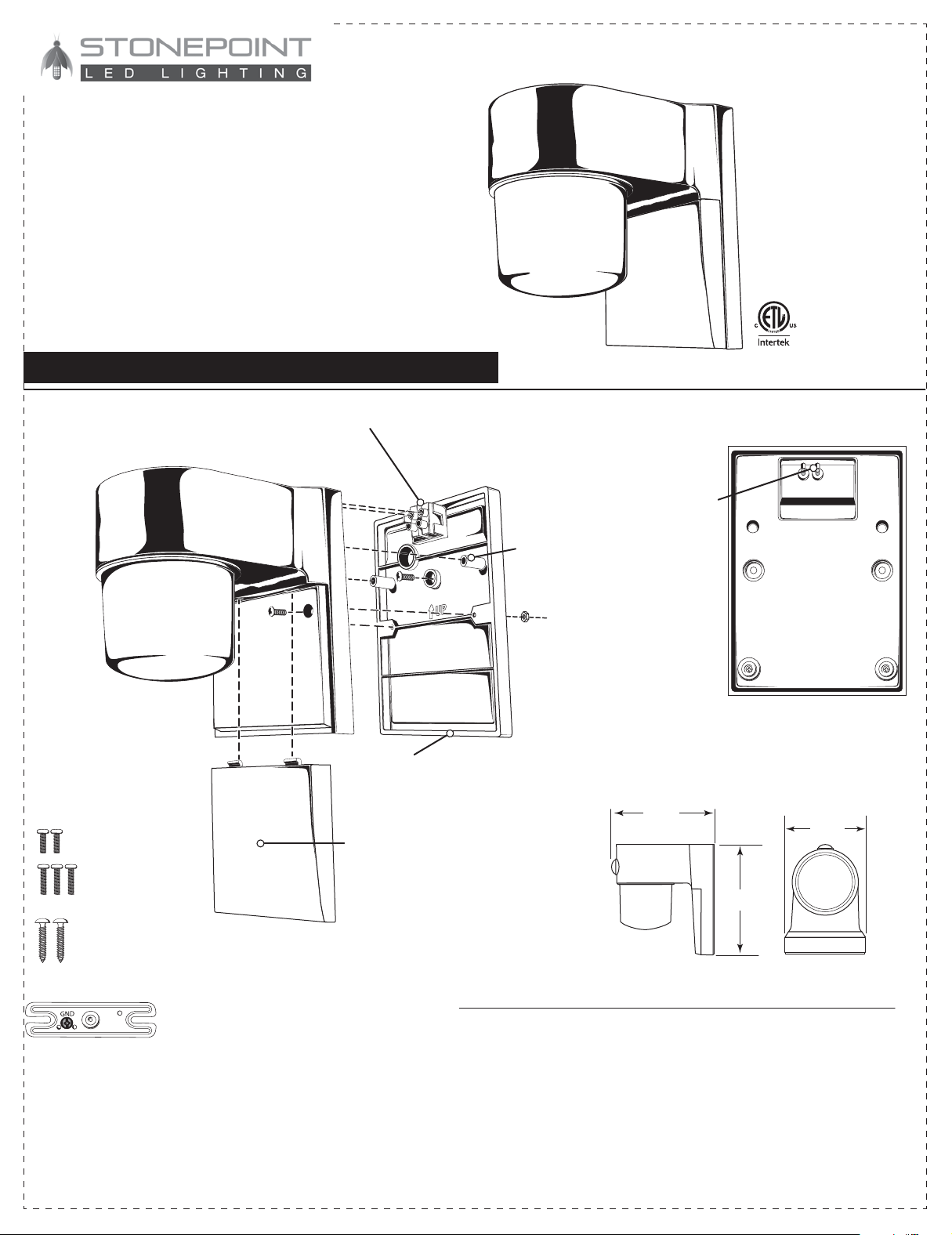
2. Feed the ends of the supply wires through
the largest hole in the mounting plate (ensure
that there is enough wire to insert into the
contact terminals) (Fig. 3). Line up the center
hole (located above the “Arrow“and “UP”
molded into the mounting plate) and the
center hole in the mounting bracket. Insert the
remaining long machine screw and tighten
until the mounting plate is securely attached to
the junction box (Fig. 4).
Terminal L
LIVE
Terminal N
NEUTRAL
4. The security light fits onto the mounting
plate in a specific manner. There are two (2)
tapered posts in the middle of the mounting
plate, one at the right and one at the left. They
fit into two (2) corresponding holes on the
back side of the fixture (Fig. 7). Line the holes
and posts up and guide the fixture onto the
mounting plate already attached to the
junction box. There are also 2 contact pins
that align and will engage the terminal block
on the mounting plate (Fig. 8).
5. While holding the fixture in place, insert the two
(2) shorter machine screws through the two (2)
holes in the front of the fixture and into the
mounting plate (Fig. 9). Tighten both screws
properly to secure the fixture to the mounting
surface (Fig. 10). Restore the power to the junction
box. Make sure the wall switch that controls the
electrical box for your security light is returned to
the “ON” position and check that the light is
functioning properly.
3. Insert the wires into their designated contact
terminals (Fig. 5). Insert the Black Supply Wire
(Live) into the terminal marked “ ”, insert the
White Supply Wire (Neutral) into the terminal
marked “ ”(Fig. 6) and tighten screws to both
terminals (Fig. 7).
1. Pull the ends of the supply wires out the
front of the junction box. Use the included
long screws to fasten the mounting bracket to
the junction box. Position the mounting
bracket with ground screw facing out (Fig. 1).
Tighten down both box screws and attach the
junction box ground wire with the green
ground screw on the mounting bracket (Fig. 2).Fig. 1 Fig. 2
Mounting bracket
Front Access Panel
Mounting plate
Contact terminals
Tapered posts
Contact pins
INSTALLATION (CONTINUED)
OPTIONAL
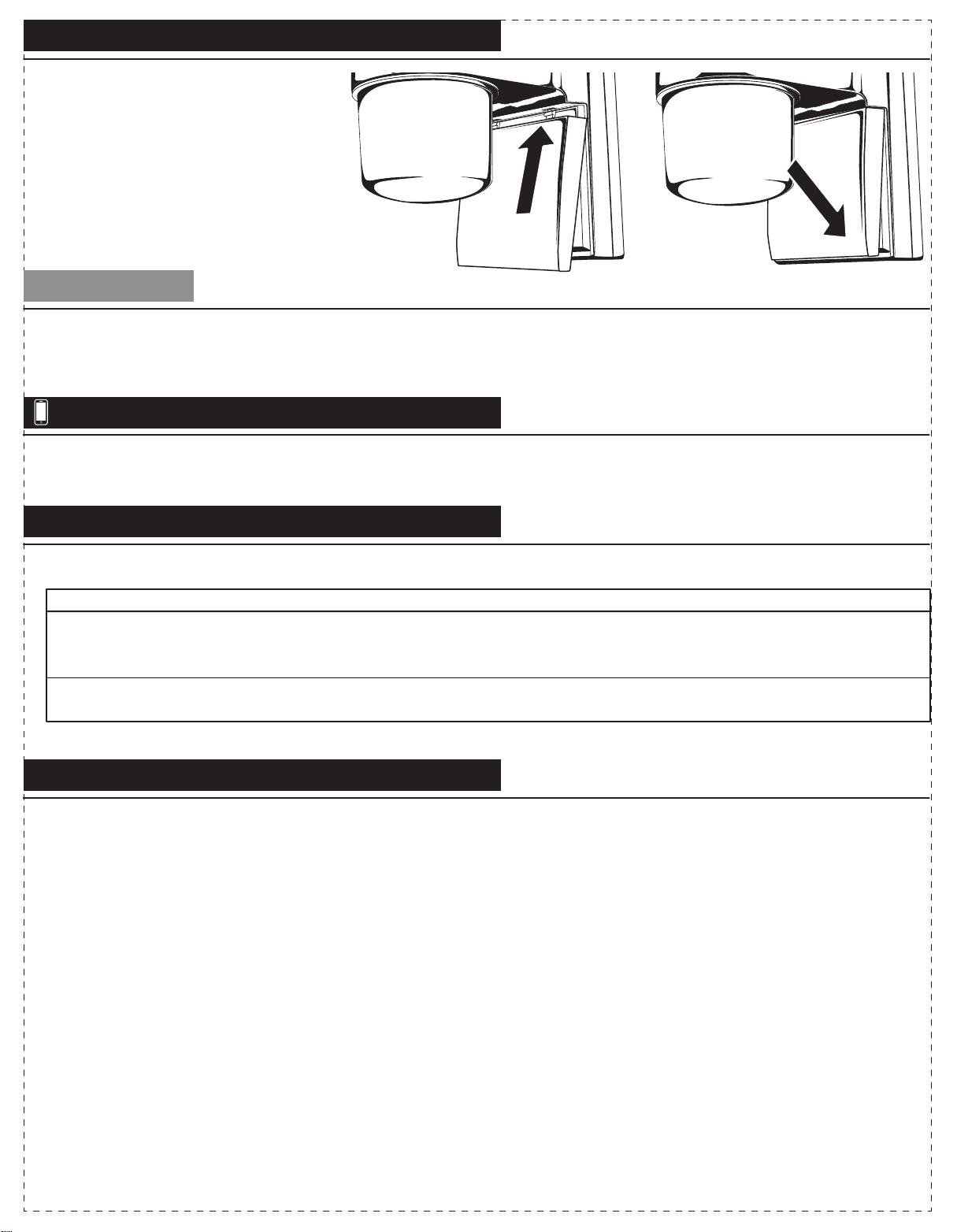
6. If the light is functioning properly,
place the front access to the fixture
housing (Fig. 11). First, angle the two (2)
locking tabs at the end of the front access
panel into the two square holes behind
the diffuser. Once the two (2) tabs are
engaged, push down at the bottom of the
front access panel until it snaps closed
(Fig. 12).
Fig. 5
Fig. 6
Fig. 7
Fig. 9 Fig. 10
Fig. 8
7. Use silicone seal/caulking (not included) to seal-off around the mounting plate and the mounting surface to add an additional barrier
to prevent water seepage into the electrical enclosure.
Fig. 11 Fig. 12
Fig. 4
Fig. 3
Mounting Bracket
1
3
4
2
Mounting Plate
6 in.
15,24 cm
5.75 in.
14,6cm 4.5 in.
11,43cm
2x
Wood screws
2x (short)
machine screws
3x (long)
machine screws
Wall Mount
Security Light
Switch Operated
MODEL No: JJ-700-SB
PACKAGE CONTENTS
INSTALLATION INSTRUCTIONS
ADDITIONAL WARNINGS
3 YEAR LIMITED WARRANTY
This product is guaranteed against failure due to factory defects on materials or workmanship for three (3) years from the date of
purchase. This warranty is non-transferable and applies only to the original owner. Proof of purchase is required for repair or
replacement. This warranty does not cover normal wear of parts or damage resulting from any misuse of the product. Misuse of the
product includes, but is not limited to: washing the product, using in extreme weather conditions, opening the product, or trying to
remodel the product. Important: this warranty is only valid if the product has been purchased through an authorized reseller.
WARNINGS
WARNING: This product may represent a possible shock or
fire hazard if improperly installed or mounted. Products should
be installed following these instructions, local electrical codes and/or
the current National Electric Code (NEC).
WARNING: This product needs to be gr ounded proper l y i n a
manner consistent wi th local elec tr i c al codes and/ or the
current National Electric Code (NEC). If the installer cannot
deter mi ne i f the pr oduc t i s pr operly grounded, has no gr ound wi r e,
or is unfamiliar with electr i c al wi r i ng methods of proper l y
grounding fixtur e, consult a quali fied el ectr i c i an.
WARNING: Do NOT look directly at LED light sources.
This fixture is IP54 rated and therefore suitable for dry,
damp and wet locations both indoor and outdoor.
WARNING: Use only in 120VAC, 60Hz circuits.
WARNING: Do NOT mount on ground.
WARNING: TO AVOID ELECTRIC SHOCK,
DISCONNECT POWER BEFORE INSTALLING
SAFETY AND PRECAUTIONS
1. Suitable for wet locations.
2. Do NOT touch LEDs.
3. Do NOT look directly at LED light sources.
4. The LED modules used in this fixture are not serviceable.
5. Do NOT make contact or install fixture while making contact with water.
6. NOT suitable for ground installations. Do NOT mount below 5 ft.
7. This product is inspected prior to shipping. Do not use if product is cracked, broken or missing parts.
8. Suitable for use in operating environments ranging between -13° F to 122° F (-25° C to 50° C).
9. Do NOT leave bare wires exposed outside of the electrical connections.
10. Electrical requirements can be found on back of the fixture.
11. If unsure how to install a light fixture, call a qualified electrician.
12. Do NOT install near other sources of light. Nearby light sources may prevent sensor from detecting darkness.
• Shut off power at the circuit breaker or fuse box before installing or servicing this fixture.
CUSTOMER SERVICE
For questions regarding this product, please contact us at 303.652.6164, M-F 7am - 4pm MT or e-mail us at
Before beginning, disconnect the power to the junction box. If replacing an existing fixture with more than two wire
leads, make a note as to where they were connected.
The user is cautioned that any changes or modifications not expressly approved by the party responsible for compliance could void the
user’s authority to operate the equipment. This equipment has been tested and found to comply with the limits for a Class B digital
device, pursuant to Part 15 of the FCC rules. These limits are designed to provide reasonable protection against harmful interference in
a residential installation. This equipment generates, uses and can radiate radio frequency energy and, if not installed and used in
accordance with the instructions, harmful interference to radio communications may occur. However, there is no guarantee that the
interference will not occur in a particular installation.
If this equipment does cause harmful interference to radio or television reception, which can be determined by turning the equipment
off and on, the user is encouraged to try to correct the interference by one or more of the following measures: Reorient or relocate the
receiving antenna. Increase the separation between the equipment and receiver.
Connect the equipment into an outlet on a circuit different from that of the receiver. Consult the dealer or an experienced radio/TV
technician for help.
WARNING: LEDs are semiconductors and can be damaged by Electro Static Discharge (ESD)(static electric shock). It is recommended
that before installation, the installer discharge themselves by touching a grounded bare metal surface to remove this hazard.
Mount fixture above 5ft.
Electrical requirements can be found on fixture.
Use with a Minimum 90° supply conductors.
Revision Date: 07-10-2017
TROUBLESHOOTING GUIDE
CLEANING INSTRUCTIONS
Disconnect power to fixture before cleaning. Using a soft cloth, clean the fixture using a mild, non-abrasive glass cleaner. DO NOT
use solvents. DO NOT use cleaners containing abrasive agents. NEVER spray liquid cleaner directly onto the LEDs, fixture or wiring.
Before starting work to connect the fixture, shut off power supply at the circuit breaker panel to avoid electrical shock.
Fixture does not turn on.
Problem Probable Cause
Solution
1. Bad connection.
2. Faulty switch.
3. Power is off.
1. Check wiring connections.
2.Test switch or replace it.
3.Verify power supply is on.
Circuit breaker trips or fuse blows
when light is turned on.
Discontinue use
immediately.
1.Call customer service at 303.652.6164.
2.Call an electrician.
WARNING: DO NOT alter or disassemble the fixture, it
is completely enclosed does not contain replaceable
parts.
DIMMING
• THIS FIXTURE DOES NOT WORK WITH DIMMERS.
LED Facts:
Color temperature: 4000K
Lumen: 700 LM
Lumen Efficiency: 80
Input Voltage: AC120/60Hz
Rated Watts: 9W
Equivalent: 75W incandescent, 23W CFL
Power Efficiency: 88%
LED Emitter Life: 50,000 hours
Cold start operating temperature: -13° F to 122° F (-25° C to 50° C)
2. Feed the ends of the supply wires through
the largest hole in the mounting plate (ensure
that there is enough wire to insert into the
contact terminals) (Fig. 3). Line up the center
hole (located above the “Arrow“and “UP”
molded into the mounting plate) and the
center hole in the mounting bracket. Insert the
remaining long machine screw and tighten
until the mounting plate is securely attached to
the junction box (Fig. 4).
Terminal L
LIVE
Terminal N
NEUTRAL
4. The security light fits onto the mounting
plate in a specific manner. There are two (2)
tapered posts in the middle of the mounting
plate, one at the right and one at the left. They
fit into two (2) corresponding holes on the
back side of the fixture (Fig. 7). Line the holes
and posts up and guide the fixture onto the
mounting plate already attached to the
junction box. There are also 2 contact pins
that align and will engage the terminal block
on the mounting plate (Fig. 8).
5. While holding the fixture in place, insert the two
(2) shorter machine screws through the two (2)
holes in the front of the fixture and into the
mounting plate (Fig. 9). Tighten both screws
properly to secure the fixture to the mounting
surface (Fig. 10). Restore the power to the junction
box. Make sure the wall switch that controls the
electrical box for your security light is returned to
the “ON” position and check that the light is
functioning properly.
3. Insert the wires into their designated contact
terminals (Fig. 5). Insert the Black Supply Wire
(Live) into the terminal marked “ ”, insert the
White Supply Wire (Neutral) into the terminal
marked “ ”(Fig. 6) and tighten screws to both
terminals (Fig. 7).
1. Pull the ends of the supply wires out the
front of the junction box. Use the included
long screws to fasten the mounting bracket to
the junction box. Position the mounting
bracket with ground screw facing out (Fig. 1).
Tighten down both box screws and attach the
junction box ground wire with the green
ground screw on the mounting bracket (Fig. 2).Fig. 1 Fig. 2
Mounting bracket
Front Access Panel
Mounting plate
Contact terminals
Tapered posts
Contact pins
INSTALLATION (CONTINUED)
OPTIONAL
6. If the light is functioning properly,
place the front access to the fixture
housing (Fig. 11). First, angle the two (2)
locking tabs at the end of the front access
panel into the two square holes behind
the diffuser. Once the two (2) tabs are
engaged, push down at the bottom of the
front access panel until it snaps closed
(Fig. 12).
Fig. 5
Fig. 6
Fig. 7
Fig. 9 Fig. 10
Fig. 8
7. Use silicone seal/caulking (not included) to seal-off around the mounting plate and the mounting surface to add an additional barrier
to prevent water seepage into the electrical enclosure.
Fig. 11 Fig. 12
Fig. 4
Fig. 3
Mounting Bracket
1
3
4
2
Mounting Plate
6 in.
15,24 cm
5.75 in.
14,6cm 4.5 in.
11,43cm
2x
Wood screws
2x (short)
machine screws
3x (long)
machine screws
Other StonePoint Floodlight manuals


