Rotary SM122-100 Series User manual

1
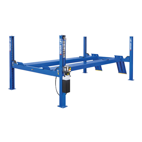
FOUR POST
SURFACE MOUNTED LIFT
Printed Mar.;Entirecontents©1998byRotaryLift.Allrightsreserved. OM-30006
OWNER’SMANUAL
TableofContents
SAFETY INSTRUCTIONS .........................................2
OWNER/EMPLOYER RESPONSIBILITIES ..............2
OPERATING INSTRUCTIONS ..................................3
MAINTENANCE INSTRUCTIONS.............................4
TROUBLE SHOOTING..............................................6
Model SM122-100 Series
WorldHeadquarters:
ROTARY LIFT
A DOVER INDUSTRIES COMPANY
2700LanierDrive
Madison,IN47250-1753USA
Phonetoll-free:1-800-445-5438
1-(812)273-1622
FAXtoll-free:1-800-822-6502
1-(812)273-6502
E-mail:[email protected]
http://www.rotarylift.com/
ForCanada:
DOVER CORP. CANADA, LTD.
ROTARY LIFT DIVISION
130BridgelandAvenue,Unit210
Toronto,Ontario
CanadaM6A1Z4
1-(416)256-4100
Fax:1-(416)256-3924
ForUnitedKingdom&
RepublicofIreland:
ROTARY LIFT (UK) LIMITED
MadisonHouse
2ParkRoad
Dartford,Kent
DA11SL
Phone:+44(0)1322223323
Fax:+44(0)1322222454
For Europe:
ROTARY LIFT EUROPE
BerlinerRing163B
D-64625Bensheim
Phone:+49(0)6251.787037
Fax::+49(0)6251.787038
READ ALL MANUALS THROUGHLY BEFORE
INSTALLING, OPERATING, OR MAINTAINING THE LIFT
ATTENTION!!!
PART OF LITERATURE PACKAGES: LP30029,LP30048

2
SAFETY INSTRUCTIONS
Neverallow unauthorized or untrained persons to
operate lift or rolling jacks.
ShopPolicyshould prohibit customers or non-author-
ized persons from being in shop area while lift is in
use.
Thoroughlytrain all employees in the use and care of
lift and rolling jacks.
Be Sure no one is standing in front or behind lift while
vehicle is being driven onto or backed off the lift.
DONOT allow rear tires or portion of vehicle to interfere
withramp/chocks.
BeSure front wheel stops are in raised position before
driving vehicle onto lift.
Neverallow front wheels to strike the front wheel stops.
DONOTpermit employees or customers on lift when it
is either being raised or lowered.
Always stand clear of lift when raising or lowering and
observe "Pinch Points" Warning.
OWNER/EMPLOYER RESPONSIBILITIES
The Owner/Employer:
Shallestablishprocedurestoperiodically maintain,
inspect and care for the lift in accordance with the
manufacturer'srecommended procedurestoensure its
continuedsafeoperation.
Shallprovide necessarylockout/tagoutsof energy
sources per ANSI Z244.1 - 1982 before beginning any
liftrepairs.
Shall not modify the lift in any manner without the
prior written consent of the manufacturer.
Shall display the operating instructions and "Lifting It
Right", supplied with the lift, in a conspicuous location
in the lift area convenient to the operator.
Shall ensure that lift operators are instructed in the
proper and safe use and operation of the lift using the
manufacturer's instructions and "Lifting It Right" and
"Safety Tips" supplied with the lift.
RotaryLift requires thatafilter/regulator/lubricator
be installed between the air source and the lift (P.N.
FA2259).
Neveroverloadlift:capacity ofliftis 12,000lbs.(6,000 lbs.
per axle). Capacity should not be exceeded.
Alwaysengage parking brake and use the rear wheel
chocks to keep the vehicle from rolling freely on the
runways.
Alwayslower lift on locks before working on vehicle.
Keep area around lift clean of tools, debris, grease,
andoil.
Alwayskeep runway clean.
Replace all caution, warning, or safety related decals
on the lift when unable to read or missing.
For Rolling Jack Safety Instructions see Rolling Jack
Installation,OperationandMaintenance Instructions
in the rolling jack box.

3
CAUTION
Keep hands clear
of yoke ends
during lift
operation.
Fig. 2
OPERATING INSTRUCTIONS
Fig. 3
Triangular
Wheel Stops Rear Wheel
Chock
Fig. 1
CAUTION
CAUTION
WARNING
To avoid personal injury and/or
property damage, permit only trained
personnel to operate lift.
After reviewing these instructions, get familiar with lift
controls by running the lift through a few cycles before
loading vehicle on lift.
Observe and heed SAFETY and WARNING labels on
the lift.
1. Loading: Lift must be fully lowered and no one in
service bay while the vehicle is brought on lift.
2. If lift is equipped with rolling jacks, jacks must be
fully lowered and the rear jack pushed toward center
of lift to provide under car clearance.
3. Drive vehicle onto lift and stop when vehicle's front
wheels are centered on turning radius gauges. On
lifts not used for wheel alignment, stop vehicle when
it is centered on runways. At all times, be sure rear
wheels are forward of the ramp/chocks and the ramp/
chocks will clear tires when the lift is raised, Fig. 1.
Driver and passengers must exit before raising.
4. Place triangular wheel chocks on each side of one of
the rear tires, Fig. 1.
5. To Raise Lift: Push the "RAISE" button on the
power unit. Release button at desired height, Fig. 2.
6. For Rolling Jack Operating Instructions see Rolling
Jack Installation, Operation and Maintenance
Instructions in the rolling jack shipping carton.
7. Before Lowering Lift: Be sure no one is in the lift
area and that all tools, tool trays, etc. have been
removed from under the lift and vehicle.
Latch Release
Air Button
LOWERING
Handle
RAISE
Button
The runways, ramps and connecting
yokes at each end of lift are designed
to rest on the floor when fully lowered. Observe
pinch point warning decals, Fig. 3.
8. Repeat Step 2.
9. To Lower Lift: If lift has been resting on the locking
latches, lift must be raised high enough for all four
latches to clear the latch plate slots inside the
columns.
10. Actuate the latch release air button on power unit to
disengage all four locking latches, Fig. 2. Hold
button in until lift has fully lowered.
Note: If button on air valve is released, the latches will
automatically reset to the engaged position.
11. Push the lowering handle on the power unit to lower
lift, Fig. 2. Lowering speed can be controlled by the
force applied to the lowering handle.
12. Observe lift and vehicle to be sure lift is level while
being lowered. If not, STOP repeat Steps 10
through 13.
13. Fully lower lift, remove the triangular wheel chocks
and check to be sure area is clear before removing
vehicle from lift, Fig. 1.
14. If your lift is not operating properly, DO NOT use
until adjustments or repairs have been made by
qualified lift service personnel.
Keep hands clear of yoke ends while the
lift is being raised or lowered, Fig. 3.
Column
Cable
Yoke End
Sheave

4
MAINTENANCE INSTRUCTIONS
WARNING
Monthly: Check cable. Adjust per instructions.
Monthly: Check level of runway. Adjust per instruc-
tions.
Monthly: Lubricate Guide on each turning radius with
a dry film lubricant. Clean and lubricate more often as
conditionswarrant.
Semi-Annually: Check fluid level of lift power unit
and refill if required. If fluid is required, inspect all
fittings, hoses and seals. Repair as required.
Semi-Annually:Lubricate front wheel stop and ramp/
chock hinge pins.
Cableadjustmentshouldbecheckedby
aRotary Authorized Installerafterthe
first 50 loaded lift cycles and after 300 loaded lift cycles.
ForRollingJack Maintenance Instructions see Rolling
JackInstallation, OperationandMaintenance Instruc-
tions in the rolling jack box.
WARNING
Replace if
bent
IMPORTANT
If you are not completely familiar with
automotiveliftmaintenanceprocedures,
STOP. Contact factory for instructions.
To Avoid Personal Injury, permit only qualified lift
servicepersonneltoperformmaintenanceonthis
equipment.
Periodically: Check all column, lift/runway attaching
boltsfor tightness.
Alwaysraise lift when cleaning floor area with solvents
and/orcleaningcompounds.
Daily: Check cables and sheaves for wear. Replace
worn parts as required with genuine Rotary parts.
Daily: Inspect front wheel stops and ramp/chocks for
damage or excessive wear. Replace as required with
genuineRotary parts.
Daily: Check locking latch operation and reset. Adjust
per instructions or repair if required with genuine
Rotaryparts.
If slack cable arm is bent, Fig. 3, replace
immediately.
Weekly: Clean foreign debris from rear wheel slip
plates and turning radius gauges by blowing out with
shop air. DONOTGREASEBALLBEARINGS.
Weekly: Check torque on the column anchor bolts per
specifications.
Fig. 3

5
5. Remove the "hair pin" cotter from the clevis pin.
6. Remove clevis pin, .
7. Replace cylinder, then do items 1-6 in reverse.
1. Lower lift onto blocks so that the latches are free to
rotate.
2. Remove air line from cylinder elbow.
3. Remove bolt that holds the cylinder to the yoke, .
4. Rotate the latch and cylinder assembly until the clevis
pin is above the yoke end, .
AIR CYLINDER REPLACEMENT
INSTRUCTIONS
1
2
3
1
3
2

6
TROUBLE SHOOTING
Trouble
Motor does not run.
Motor runs but will not raise lift.
Motorrunsraises unloadedliftbut
will not raise vehicle.
Liftslowlysettles down.
Slow lifting speed or fluid blowing out
fillerbreather cap.
Lift going up unlevel.
Lift stops short of full rise or
chatters.
Anchors will not stay tight.
Lift will not lower.
Remedy
1. Replace blown fuse or reset circuit
breaker.
2. Supplycorrect voltage to motor.
3. Repairand insulateall connections.
4. Replaceswitch.
5. Replacemotor.
1. Repairor replaceloweringvalve.
2. Tighten all suction line fittings.
3. Replacesuction stub.
4. Fill tank with Dexron III ATF.
1. Supplycorrect voltage to motor.
2. Cleanloweringvalve.
3. Replacereliefvalvecartridge.
4. Checkvehicle weight and/or
balance vehicle weight on lifts.
1. Clean check valve.
2. Cleanloweringvalve.
3. Repairexternal leaks.
1. Changehydraulicfluidto Dexron
III ATF.
2. Tighten all suction line fittings.
3. Reinstallfluid return tube.
1. Adjust slack out of cable.
2. Shim lift to level columns (Not to
exceed 1/2" per column).
Note: Shim thickness of 2" is possible
by using optional shim kit
#FC5393. Contactyour authorized
RotaryPartsDistributor for
orderinginformation.
Checkfluid levelandbleed cylinder
If fluid is required inspect all fit-
tings, hoses, and seals. Repair as
required. Clean power unit pickup
stubfilter.
1. Use a fast setting cement to pour
intooversize holes andreset
anchors -or- relocate lift using a
new bit to drill holes.
2. Break out old concrete and repour
new pads for lift.
1. Check air pressure. Air supply to
lift should be between: min. 90
p.s.i. and max. 120 p.s.i. Check all
lines and fittings for leaks or
crimps. Repair or replace as
required.
2. Checklatches
Cause
1. Check fuse or circuit breaker.
2. Check for correct voltage to motor.
3. Inspectall wiring connections.
4. Switchburned out.
5. Motorwindings burnedout.
1. Openlowering valve.
2. Pump sucking air.
3. Suction stub off pump.
4. Lowfluidlevel.
1. Motor running on low voltage.
2. Trash in lowering valve.
3. Improperreliefvalveadjustment.
4. Overloadinglift.
1. Trash in check valve seat.
2. Trash in lowering valve seat.
3. Externalfluid leaks.
1. Air mixed with fluid.
2. Air mixed with fluid suction.
3. Fluid return tube loose.
1. Cablesout of adjustment.
2. Liftinstalledonunlevelfloor.
Low on fluid.
1. Holesdrilledoversize.
2. Concretefloor thicknessorholding
strengthnot sufficient.
1. Insufficient air supply to lift.
2. Latches out of adjustment.

7
Notes:

8
This equipment
complies with American
National Standard B-153.1
Installer: Please return this booklet to literature package and
GIVE TO LIFT OWNER/OPERATOR.
Trained Operators and Regular Maintenance Ensures
Satisfactory Performance of Your Rotary Lift.
Contact Your Nearest Authorized Rotary Parts Distributor for Genuine Rotary
Replacement Parts. See Literature Package for Parts Breakdown.
WorldHeadquarters:
ROTARY LIFT
A DOVER INDUSTRIES COMPANY
2700LanierDrive
Madison,IN47250-1753USA
Phonetoll-free:1-800-445-5438
1-(812)273-1622
FAXtoll-free:1-800-822-6502
1-(812)273-6502
E-mail:[email protected]
http://www.rotarylift.com/
ForCanada:
DOVER CORP. CANADA, LTD.
ROTARY LIFT DIVISION
130BridgelandAvenue,Unit210
Toronto,Ontario
CanadaM6A1Z4
1-(416)256-4100
Fax:1-(416)256-3924
ForUnitedKingdom&
RepublicofIreland:
ROTARY LIFT (UK) LIMITED
MadisonHouse
2ParkRoad
Dartford,Kent
DA11SL
Phone:+44(0)1322223323
Fax:+44(0)1322222454
For Europe:
ROTARY LIFT EUROPE
BerlinerRing163B
D-64625Bensheim
Phone:+49(0)6251.787037
Fax::+49(0)6251.787038
SV0021 Rev. 4/9/99
Rotary Lift is authorized to apply ETL Listing Marks/Labels to
this AC Motor. Authorization: ETL Report No. J98007541-003,
FAM-UL73.This ETL test certifies that this AC Motor complies
with Underwriters Laboratories, Inc.standard ANSI/UL 73
8th Edition.
Certificate of Compliance
Table of contents
Other Rotary Lifting System manuals

Rotary
Rotary S42N46CAT-I Instruction Manual

Rotary
Rotary VLXS7 User manual

Rotary
Rotary 2000 Series User manual

Rotary
Rotary E Series User manual

Rotary
Rotary MASTER GEAR MGE 2.0 Manual

Rotary
Rotary SPOA3TE 600 Series User manual

Rotary
Rotary XS35 Troubleshooting guide

Rotary
Rotary SPOA7 Series User manual

Rotary
Rotary SM40-47 User manual

Rotary
Rotary 100 Series User manual

Rotary
Rotary Sprinter SPO15 User manual

Rotary
Rotary 100 Series User manual

Rotary
Rotary SPO16 User manual

Rotary
Rotary 200 Series User manual

Rotary
Rotary XMB600 Manual
Rotary
Rotary SPO16 User manual

Rotary
Rotary GAR324 User manual

Rotary
Rotary SM65-51 User manual

Rotary
Rotary 100 Series User manual
Rotary
Rotary XS30 User manual