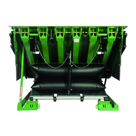
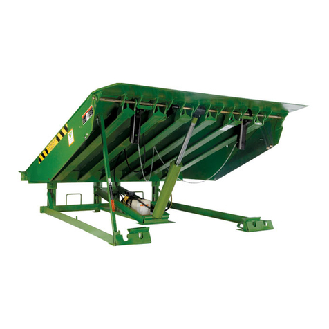
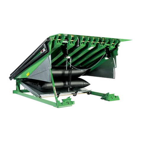
Kelley HK-S User manual

Do not install, operate or service this product unless you
have read and understand the Safety Practices, Warnings,
and Installation and Operating Instructions contained in
this User’s Manual. Failure to do so could result in death
or serious injury.

Indicates an imminently hazardous situation which, if
not avoided, will result in death or serious injury.
Indicates a potentially hazardous situation which,
if not avoided, could result in death or serious
injury.
Indicates a potentially hazardous situation which,
if not avoided may result in minor or moderate
injury.
Notice is used to address practices not related to
personal injury.
This is the safety alert symbol. It is used
to alert you to potential personal injury
hazards. Obey all safety messages that
follow this symbol to avoid possible death or injury.

Read these safety practices before installing, operating
or servicing the Dock Leveler. Failure to follow the safety
practices could result in death or serious injury.


Ramp grade
Lip grade
7° lip bend, 16" lip (optional special order)4° lip bend, 16" lip.
6' Leveler 8' Leveler 10' Leveler
Vehicle bed
position
from dock,
(in.) Ramp Lip Ramp Lip Ramp Lip
Above dockBelow dock
Ramp and lip grades,
% for each dock leveler length
6' Leveler 8' Leveler 10' Leveler
Vehicle bed
position
from dock,
(in.) Ramp Lip Ramp Lip Ramp Lip
Above dockBelow dock
Ramp and lip grades,
% for each dock leveler length
18.0
16.0
14.0
12.0
10.0
8.0
6.0
4.0
2.0
0.0
-2.0
-4.0
-6.0
-8.0
-10.0
-12.0
---
---
---
19.4
16.5
13.7
10.8
8.0
5.2
2.4
-0.3
-3.1
-5.9
-8.7
-11.5
-14.4
---
---
---
11.6
8.7
5.8
3.0
0.2
-2.6
-5.4
-8.2
-11.0
-13.8
-16.6
-19.4
-22.2
---
---
---
14.5
12.3
10.2
8.1
6.0
3.9
1.8
-0.3
-2.3
-4.4
-16.5
-8.6
-10.7
---
---
---
6.6
4.5
2.4
0.2
-1.8
-3.9
-6.0
-8.1
-10.2
-12.3
-14.4
-16.5
-18.6
16.7
15.0
13.2
11.5
9.8
8.2
6.5
4.8
3.1
1.5
-0.2
-1.9
-3.5
-5.2
-6.9
-7.5
8.8
7.1
5.4
3.7
2.0
0.3
-1.4
-3.1
-4.7
-6.4
-8.1
-9.7
-11.4
-13.1
-14.7
-15.3
18.0
16.0
14.0
12.0
10.0
8.0
6.0
4.0
2.0
0.0
-2.0
-4.0
-6.0
-8.0
-10.0
-12.0
---
---
---
20.5
17.6
14.7
11.9
9.1
6.3
3.5
0.7
-2.1
-4.9
-7.7
-10.5
-13.3
---
---
---
8.0
5.0
2.2
-0.7
-3.5
-6.3
-9.1
-11.9
-14.6
-17.4
-20.2
-23.0
-25.9
---
---
---
15.3
13.1
11.0
8.9
6.8
4.7
2.6
0.5
-1.6
-3.6
-5.7
-7.8
-9.9
---
---
---
2.7
0.6
-1.6
-3.7
-5.8
-7.9
-10.0
-12.0
-14.1
-16.2
-18.3
-20.4
-22.5
17.3
15.6
13.9
12.2
10.5
8.8
7.1
5.4
3.8
2.1
0.4
-1.2
-2.9
-4.6
-6.3
-7.9
4.8
3.0
1.3
-0.4
-2.1
-3.8
-5.5
-7.1
-8.8
-10.5
-12.1
-13.8
-15.5
-17.1
-18.8
-20.5

12"
14"
Box located as
shown
Pit
center
line
Push-button
control station
48"
Place barricades around pit on dock oor and drive while
installing, maintaining or repairing dock leveler.
Power to control box must be from fused disconnect
supplied by others. For correct fuse size refer to wiring
diagrams on pages 15-24 of this manual. Fuses to be
class CC time delay. Before doing any electrical work,
make certain the power is disconnected and properly
tagged or locked off. All electrical work must be done
by a qualied technician and must meet all applicable
codes. If it is necessary to make troubleshooting checks
inside the control box with the power on, USE EXTREME
CAUTION. Do not place ngers or uninsulated tools inside
the control box. Touching wires or other parts inside the
control box could cause electrical shock, resulting in
death or serious injury.

Before installing the dock leveler, read and follow the
Safety Practices on page 3. Failure to follow the Safety
Practices could result in death or serious injury.
Inadequate lifting equipment or practices can cause a
load to fall unexpectedly. Make sure the lifting chain or
other lifting devices are in good condition and have a
rated capacity of at least 3500 lbs for the lifting angle
used. Never allow anyone to stand on or near the dock
leveler when it is lifted or placed into the pit. Stand clear
of the dock leveler when it is placed into the pit. Failure to
follow this warning can allow the dock leveler to fall, tip,
or swing into people, resulting in death or serious injury.
Route power cord clear of edges and resting surfaces so
that it is not damaged during lifting and placement. Wires
may be routed up through the rear hinge until needed.
3/4" - 10 UNC
load centering
eyebolt

The rear edge of the dock leveler should be level or
slightly (1/16" maximum) below dock level.
The top surface of the dock leveler should be level and
a smooth transition with the dock oor curb steel. The
front end should be level and parallel with the rear frame
angle for proper operation. Unequal Shimming of the
front supports may be required to obtain a level front
edge.
Turn off all electrical power to the leveler if it has been
previously connected. Welding with dock levelers power
connected can damage the electrical components. A
ground must be attached to the leveler frame. Failure to
do so can result in product damage.
1/2"

Bevel groove weld locations
Frame
uprights
Rear hinge
assembly
Pit
rear
curb
angle
2-1/2"
5"
2-1/2"
5"
5"
5"
2-1/2"
5"
2-1/2"
5"
Rear pit
curb angle
Pit side curb angle
Ramp
Rear
frame
angle
1/2" 1/2"
Before welding the dock leveler supports to the front
curb angle make sure that the dock leveler support legs
line up with the “V” pocket in the dock leveler support
angle. Move dock levelers support right or left for the
necessary alignment.
Raises
rear
angle
Transition angle
Curb
angle
Leg
adjustment
1/4"
Legs are in contact
with pit floor when
the leveling screws
are 1/4" from the
top of the transition
angle

Cylinder
mounting pad
3/4"
anchor
bolt
(supplied
by others)
Stagger and weld
6" x 12" shims
Hydraulic pressure or mechanical support must be
maintained on the ramp and lip to hold them in the raised
position until the maintenance strut and lip lock are in
place. DO NOT WORK UNDER THE DOCK LEVELER
RAMP OR LIP UNLESS THE MAINTENANCE STRUT IS IN
PLACE AND PINNED, AND LIP LOCK IS IN PLACE AND
SUPPORTING THE LIP.
Flush with floor at this point
Door jamb
1/2" sq. drive
adjustment bolt
CCW rotation
to raise
3/16" weld
(both sides)
3/16" weld
3" long (min.)
(both sides)
3/16" weld
(both sides)
3/16" weld
3" long (min.)
(both sides)
3/16" weld
3" long (min.)
3/16" weld
3" long (min.)
3/16" weld
Curb steel
Curb steel

Remove
shipping
cotter pins
Welding with the dock levelers power connected can
damage electrical components. If the dock leveler has
been previously connected, turn off power to control box
and disconnect all electrical wires from junction box in
rear pit wall before welding. Failure to do so can result
in product damage.
Improper installation of anchoring devices or installation
into aged or unsound concrete could result in death or
serious injury.
Maintenance
strut bracket
Insert hairpin
clip through
maintenance
strut pin
Maintenance
strut pin
Maintenance
strut
Lip Lip
lock
Shipping tie
down bolt

3"
1" Dia.
4"
J bolts (3) per bumper
furnished by Kelley
Company, Inc. Locate
and weld to curb
angle at time of
bumper installation.
Molded “L” bumpers
Improper installation of anchoring devices or installation
into aged or unsound concrete could result in death or
serious injury.
The dock face must be ush with curb angle to assure
proper bumper mounting.
Manually support the lip when storing the lip lock. Stand
clear of the lip when removing support. The lip is free to
move downward when support is removed. Anyone in the
path of the lip when it moves downward can be struck.
Keep your hands, ngers and head away from the lip
when it is released. They could be struck by the lip or
caught between the lip and other parts of the dock leveler
resulting in death or serious injury.
DO NOT REMOVE MAINTENANCE STRUT WITHOUT
HYDRAULIC PRESSURE OR A MECHANICAL LIFTING
DEVICE SUPPORTING RAMP. Raise ramp with
hydraulic pressure or mechanical device before storing
maintenance strut. Stand clear of ramp and lip when
hydraulic pressure or mechanical lift is applied or
removed. Ramp and lip are free to move downward
when support is removed. Removing support without
hydraulic pressure could allow ramp to drop RAPIDLY. If
the dock leveler was raised using a mechanical device,
it should be lowered using the same device.
Vertical
bumper
mounting
angle
Laminated bumpers
3/8" side of pit
to side of bumper
mounting plate
1/4"
Laminations must be
installed vertically
Full length of bumper
mounting plate.
downhill welds are
unacceptable.
1/4"
To
curb
angle
3/4" dia.
anchor bolt.
field installed.
Supplied by
others.

Warning and operating
instruction placard
OPERATIONS
Cap plug
Rear angle
Improper installation that allows the pendant dock leveler
lip to support the weight of the dock leveler could result
in death or serious injury. It is sometimes necessary to
install lip deector plates to avoid any chance of the
pendant lip supporting the weight of the dock leveler
either near dock level or during a below dock end load.

1/2" max.
1/8" MAX
allowable step
no greater than
1" x 3" in size
6"
contact
zone
Equal
gap
Shim and weld flush

Before doing any electrical work, make certain the power
is disconnected and properly tagged or locked off. All
electrical work must be done by a qualied technician
and meet all applicable codes. If it is necessary to make
troubleshooting checks inside the control box with
the power on, USE EXTREME CAUTION. Do not place
your ngers or uninsulated tools inside the control box.
Touching wires or other parts inside the control box
could result in electrical shock, death or serious injury.


This manual suits for next models
1
Table of contents
Other Kelley Lifting System manuals
Popular Lifting System manuals by other brands

BGS technic
BGS technic 8389 instruction manual

Bike-Lift
Bike-Lift PSB-20 Use and maintenance manual

STS
STS STP12-FAC01-1300KG-Ex operating instructions

CHIEF
CHIEF SMART-LIFT SL236i installation instructions

Auxx Lift
Auxx Lift 1400 owner's manual

PFlow Industries
PFlow Industries F Series Service & Maintenance and Owner’s Manual