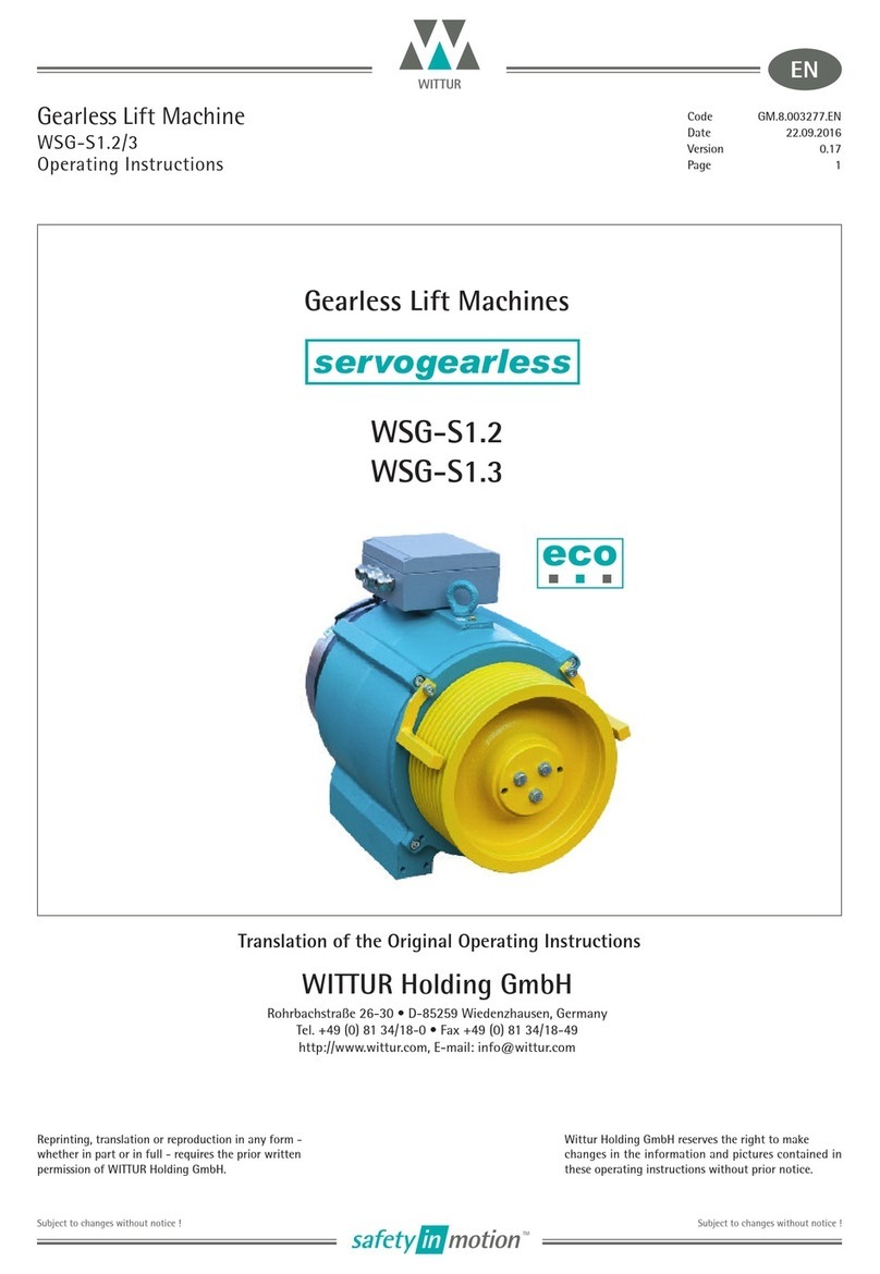
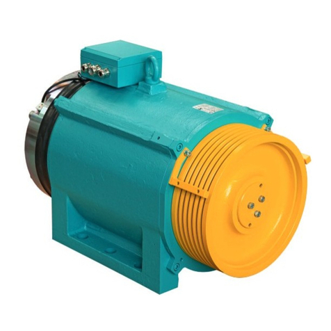
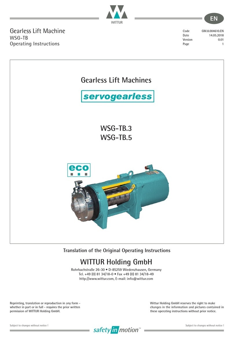
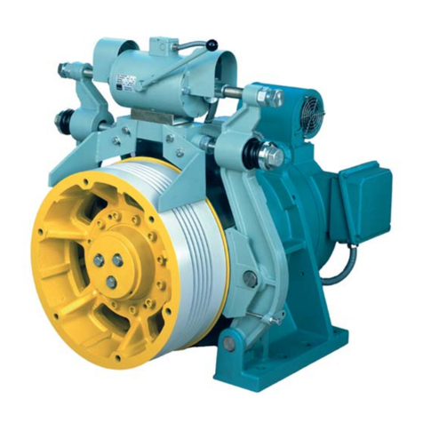
WITTUR WSG09 Operating instructions

Gearless Synchronous Lift Machines
WSG09.X
Operating and maintenance manual J40003
Page 1
Date 21.05.2015
Version E
Subject to changes without notice!
Gearless Synchronous Lift Machines
WITTUR Holding GmbH
Rohrbachstrase 26-30 . D-85259 Wiedenzhausen, Germany
Tel. +49 (0) 81 34/18-0 rFax +49 (0) 81 34/18-49
http://www.wittur.com, E-mail: info@wittur.com
Wittur Holding GmbH reserves the right to make
changes in the information and pictures contained in
these operating instructions without prior notice.
English
WSG .X09

21.05.2015
E
Gearless Synchronous Lift Machines
WSG09.X
Operating and maintenance manual J40003
Page 2
Date
Version
Subject to changes without notice!
Wittur Elevator Components (Suzhou) Co. Ltd.
18 Shexing Road,FOHO Economic Development Zone
Wujiang City, Jiangsu Province
P.R. China
Tel: +86-512-63220888
Fax: +86-512-63220044
info@wittur.com.cn
These operating instructions are
applicable to lift machines:
WSG09.X
with
block brake
Wittur Holding GmbH reserves the right to correct or change the
contents of this manual and these product details without prior
notice. We expressly reserve the right to make technical changes
which improve the lift machines or their safety standards without
prior notice. No liability can be accepted for damage, injuries or
expense arising therefrom. We cannot guarantee the correctness
and complete- ness of the details.

21.05.2015
E
Gearless Synchronous Lift Machines
WSG09.X
Operating and maintenance manual J40003
Page 3
Date
Version
Subject to changes without notice!
1. General safety instructions....................................................4
2. Product description..................................................................6
3. Nameplate...................................................................................7
4. Type code.....................................................................................8
5. Technical data............................................................................9
6. Dimension drawing ................................................................11
7. Scope of supply ...................................................................... 12
8. Transport and storage........................................................... 12
9. Installation............................................................................... 13
10. Electrical connection ............................................................ 14
10.1. General............................................................................ 14
10.2. Motor connection / Winding protection ............... 14
10.3. Speed/Position measuring system ........................... 17
10.3.1. Measuring system ECN 1313 ...................... 17
10.3.2. Measuring system ERN 1387 ...................... 18
10.4. Brake................................................................................ 19
11. Commissioning........................................................................ 20
12. Operation and maintenance............................................... 21
12.1. General............................................................................ 21
12.2. Maintenance intervals................................................ 21
12.3. Lubricating instructions ............................................. 22
12.4. Brake remote release for MRL solution ................. 22
12.5. Mechanical evacuation device................................. 22
12.6. Replacing the traction sheave.................................. 23
12.7. Brake................................................................................ 23
12.8. Replacing the measuring system............................. 26
12.9. 9.9. Trouble shooting................................................... 27
13. Accessories............................................................................... 28
13.1. Connecting cable for measuring systems ............. 28
13.2. Mechanical evacuation .............................................. 29
13.3. Brake remote release .................................................. 29
13.4. Brake manual release.................................................. 29
13.5. Mechanical evacuation device................................. 29
14. Spare parts............................................................................... 30
Index
10.3.3. Measuring system TS5213N2503. ............. 18
Annex
EC Declaration of Conformity
EC type-examination certificate WB4600
EC type-examination certificate WB3600

21.05.2015
E
Gearless Synchronous Lift Machines
WSG09.X
Operating and maintenance manual J40003
Page 4
Date
Version
Subject to changes without notice!
1. General safety instructions
Explanation of symbols used in these instructions
means that death or serious injury to persons
or serious damage to property will occur unless
the appropriate precautions are taken.
means that death or serious injury to persons
or serious damage to property may occur
unless the appropriate precautions are taken.
means that injuries to persons or damage to
property may occur unless the appropriate
precautions are taken.
points out important information and
operating instructions. If these are not
observed, damage, hazards or faults may
result.
Intended use
The WSG09.X lift machines have been manufactured in
compliance with the latest state of the art and recognised
safety regulations. They may only be used for the purpose
for which they are intended, and with all safety devices in
proper working order.
The WSG09.X may only be used for driving lifts. "Intend-
ed use" also requires that the instructions contained in
the documentation supplied with the machine and the
commissioning instructions be observed, and that the
speci ed inspection and maintenance work be carried out.
Warranty and liability
Our "Conditions of Sale and Delivery" shall apply for all our
supplies and services. The warranty is 18 month.
We do not accept any warranty or liability claims for per-
sonal injury or property damage resulting from one or more
of the following causes:
rImproper use of the WSG09.X lift machine
rImproper installation, commissioning, operation or
maintenance
rOperation of the WSG09.X with defective and/or inop-
erative safety or protective devices
Danger
Warning
Caution
Note
rNon-compliance with the instructions contained in the
operating instructions or other documentation supplied
rUnauthorised construction modi cations to the WSG09.X
rInsuf cient monitoring of parts subject to wear
rRepairs carried out improperly
rEmergencies caused by external forces or force majeure
Safety precautions
Only qualified personnel are authorized to perform any
planning, installation or maintenance work, and this must be
done in accordance with the relevant instructions.
The personnel must be trained for the job and must be
familiar with the installation, assembly, commissioning and
operation of the product.
The WSG09.X lift machines are intended for use in an
enclosed, lockable machine room or shaft to which only
qualified personnel and personnel authorised by the
customer have access.
rThe instructions given in this manual or any other
instructions supplied must always be observed to
avoid danger or damage.
rWSG09.X lift machines are not ready-to-use
products; they may only be operated after they
have been installed in lift systems and their
safe operation has been ensured by taking the
appropriate measures.
rCheck the proper functioning of the motor and the
brake after installing the machine.
rRepairs may only be carried out by the manufacturer
or an authorised repair agency. Unauthorised
opening and tempering may result in injuries to
persons and property.
rThe machines are not designed for direct connection
to the three-phase system but are to be operated
via an electronic frequency converter. Direct
connection to the mains may destroy the motor.
rThe machines can only installed by vertical
direction.
Danger
21.05.2015
E
Gearless Synchronous Lift Machines
WSG09.X
Operating and maintenance manual J40003
Page 5
Date
Version
Subject to changes without notice!
rHigh surface temperatures may occur on the
external parts of the machine. Therefore, no
temperature-sensitive parts may be in contact with
these parts or attached to them. Protection against
accidental contact should be provided, if required.
rHigh voltages are applied at the terminal
connections during the operation of synchronous
motors.
Warning

21.02.2015
E
The WSG09.X gearless synchronous lift machines are
designed solely for use with electronic frequency inverters.
The synchronous motor has been designed for various rated
torques. It can also be supplied for several rated speeds,
which can then be further adapted to meet individual
customer requirements.
Gearless Synchronous Lift Machines
WSG09.X
Operating and maintenance manual J40003
Page 6
Date
Version
Subject to changes without notice!
2. Product description
The gearless WSG09.X lift machines are designed by outer
rotor for gearless traction lifts with or without a machine
room. They are intended for operation with a 2:1 suspension
and are distinguished by their high ef ciency, extremely low
noise and excellent operating characteristics.
It is composed by housing (1), motor, traction sheave (2) and
block brake(3). The rope slip off guard is designed to avoid
the rope jumping out of the traction sheave.
The rotor shaft is inserted into the stator frame and
supported in a self-aligning roller bearing (4) at the traction
sheave side. Above it, there is a connection seats (5) which
designed for mechanical evacuation. The wheels is intent
to adapt to the system for the evacuation in emergency
situation as option. At the other side, the rotor shaft is
fixed by a supporting ball bearing (6) to the housing. the
both bearings were adapted by a heating way during the
assembly. The self-aligning roller bearing is sealed and has a
provision for re-lubrication.
The encoder system (7) is located within the centre of the
machine behind the ball bearing. The brakes are powered on
by
110V DC . The electrical connection of the motor is made
in the terminal box (8) where the temperature monitoring
device and brake contactor is also connected. The brakes are
designed such that in the case of failure of one brake the
remaining brakes are able to decelerate a car carrying a full
payload. They are also able to be released manually.
We would like to refer to the relevant patents held by KONE
Corporation for lifts without machine room.

Nm
Brake Torque:
F
Insulation Class:
IP43IP43Degree Of Prot. :
Serial No. :
CE Notify Body : TÜV SÜD
S3-60%
0.5~0.6mm
A
110V DC
Manufacture Date:
CE Certificate No. :
Duty Cycle :
Air Gap:
Rated Current:
Model Name:
Holding Voltage:
21.05.2015
E
Gearless Synchronous Lift Machines
WSG09.X
Operating and maintenance manual J40003
Page 7
Date
Version
Subject to changes without notice!
3. Nameplate
The nameplate of the lift machine is on the motor.
The nameplate of the brake is on the brake.
Type
Rated Speed Sheave Diameter
Suspension
Rated Voltage
Rated Torque
Rated Revolution
Rated Frequency
Rated Power Duty
Protection Class
Insulation Class
Weight
Hz
W
ittur Elevator Components (Suzhou) Co.,Ltd
Max.Shaft Load
Rated Load
Rated Current Pole Pairs
P=11
kg
V
A
kw
Nm
m/s
rpm
Gearless Synchronous Lift Machine
CE Notify Body
CE Certificate No.
Operation Cycle
Groove Number
F
IP40
KP
mm
240S/h
S3-40%
kg
WSG09. 35 kN
TUV SUD
Manufactured in China
Serial No.
Contract No.ke Manufacture date
V/min-1
Pull In Voltage: 110V DC

21.05.2015
E
Operating and maintenance manual J40003
Subject to changes without notice!
Gearless Synchronous Lift Machines
WSG09.X
Page 8
Date
Version
4. Type code
Motor voltage
0: Suitable for converter supply using a link voltage of 500 ...
620V DC
Example W S G- 09 . 2 - 0 0 09 / 40A - 01
W S G- 09 .
X
XXX1X2X3X4X5X6X7X8X9
--
/
Synchronous motor
Frame type
Overall length
Identifyed by: 2, 3, 4
Customer specic identifer
e.g. 01:1313 encoder, with brake manual release, with mechanism evacuation device,w/o remote brake release
09: 95r/min(with Dt=400mm v=1.0m/s, suspension 2:1)
X5X6X7 / Traction sheave design:
(Traction sheave diameter; width, groove design, groove geometry)
X8X9 Variant code(measuring system, brake manual release,mechanism evacuation device, remote brake release)
Example.

21.05.2015
E
Gearless Synchronous Lift Machines
WSG09.X
Operating and maintenance manual J40003
Page 9
Date
Version
Subject to changes without notice!
5. Technical data
Duty type S3 - 40%
Sheave Ø400mm / Ø450mm
Traction sheave hardness Min. 220 HB 30
DE Bearing self-aligning roller bearing
NDE Bearing ball bearing
Permissible shaft load Max. 35,000N
Drive motor synchronous motor
Number of pole pairs 11
Thermal class 155°(F)
Degree of protection IP40
Overload capability 2.0fold (Imax/IN)
Winding protectionḬtriple PTC 150°C
Site conditions
Max. Attitude Up to 1,000 m (At high altitude decrease this value)
Ambient temperature +5°C... +40°C
Max. rel. humidity 85%Ḟ20°C (non-condensing )
Block brake
Type WSG09.2
WSG09.3
WSG09.4
WB3600 WB3600 WB4600
Max. braking torque 2x700
Nm 2x850
Nm 2x950
Nm
Default setting 2f1.25 M
air gap 0.5mm ~ 0.6. mm
* Remark:75-80V DC for holding voltage is preferred for best performances
N
Groove prole
Rated Torque
S3-40%,240s/h MN
Sheave ΦDt
loads Q
nNPNINUNFnNPNINUNF
0.5 48 3.7 10.2 281 8.8 42 2.4 10.2 214 7.7
195 5.4 13 323 17.4 85 4.8 13 293 15.6
1.6
1.75 167 9.4 19.9 337 30.6 149 8.4 17.7 342 27.3
2 191 10.8 22.7 331 35 170 9.6 22.7 297 31.2
2.5 240 13.6 28.7 331 44 212 12 28.7 295 38.9
Rated Torque
S3-40%,240s/h MN
Sheave ΦDt
loads Q
nNPNINUNFnNPNINUNF
0.63 29 1.6 10.2 169 5.3 25 1.4 10.2 155 4.6
1 48 2.7 10.2 234 8.8 42 2.4 10.2 214 7.7
1.6 76 4.3 11 314 13.9 68 3.9 11 288 12.5
400 450
up to 400 up to 320
5xΦ10/15
γ=30
«
β=95
«
Suspension 1:1
540
Motor Type Synchronous 22-pole
WSG09.2
Suspension 2:1
400 450
up to 800 up to 630
540
Motor current
applicable to
500-620Vd.c.link
voltage DC 500-620V
Motor current
applicable to
500-620Vd.c.link
voltage DC 500-620V
[Nm]
[mm]
[kg]
[Nm]
[mm]
[kg]
v[m/s]
v[m/s]
NN
[rpm] [kW] [A] [V] [Hz]
NN[Hz][V]
[A]
[kW][rpm]
[rpm] [kW] [A] [V] [Hz] [rpm] [kW] [A] [V] [Hz]
Pull in voltage/ Holding voltage 110V DC
Nominal current 1.34A 1.34A 1.53A
in temperature rise
1.5 143 8.1 17.7 332 26.2 127 7.2 17.7 297 23.3
153 8.7 19.9 310 28.1 136 7.7 17.7 302 24.9
0.63 60 3.4 11 262 11 54 3.1 11 244 9.9

21.05.2015
E
Gearless Synchronous Lift Machines
WSG09.X
Operating and maintenance manual J40003
Page 10
Date
Version
Subject to changes without notice!
Groove prole
Rated Torque
S3-40%,240s/h
Sheave ΦDt
loads Q
n
NPNINUNFNnPNINUNF
0.5 48 3.4 11.1 270 8.8 42 2.9 11.1 244 7.7
1 95 6.7 16.5 303 17.4 85 6.0 16.5 274 15.6
1.6
1.75 167 11.7 25.2 323 30.6 149 10.5 22.5 326 27.3
2 191 13.4 28.6 322 35 170 11.9 28.6 327 31.2
2.5 240 16.8 34 325 44 212 14.9 34 288 38.9
Rated Torque
S3-40%,240s/h
Sheave ΦDt
loads Q
nNPNINUNFnNPNINUNF
0.63 29 2 11.1 194 5.3 25 1.8 11.1 178 4.6
1 48 3.4 11.1 270 8.8 42 2.9 11.1 247 7.7
1.6 76 5.3 13.4 319 13.9 68 4.8 13.4 292 12.5
400 450
up to 500 up to 400
6xΦ10/15
or 5xΦ10/15
γ=30
«
β=95
«
Suspension 1:1
670
Suspension 2:1
670
400 450
up to 1000 up to 800
Motor Type Synchronous 22-pole
WSG09.3
Motor current
applicable
to
500-620Vd.c.link
voltage DC 500-620V
Motor current
applicable to
500-620Vd.c.link
voltage DC 500-620V
Groove prole
Rated Torque
S3-40%,240s/h
Sheave ΦDt
loads Q
nNPNINUNFnNPNINUNF
0.5 48 3.7 12.3 281 8.8 42 3.3 12.5 261 7.7
1 95 7.4 18.5 311 17.4 85 6.6 18.5 288 15.6
1.5 143 11.1 25 323 26.2 127 9.8 25 250 23.3
1.75 167 12.9 30 302 30.6 149 11.5 25 277 27.3
2 191 14.8 33 311 35 170 13.2 33 312 31.2
2.5 240 18.6 40.5 310 44 212 16.4 40.5 281 38.9
Rated Torque
S3-40%,240s/h
Sheave ΦDt
loads Q
nNPNINUNFnNPNINUNF
0.63 29 2.2 12.3 204 5.3 25 1.9 12.3 187 4.6
1 48 3.7 12.3 281 8.8 42 3.3 12.3 257 7.7
1.6 76 5.9 15.7 307 13.9 68 5.3 15.7 281 12.5
7xΦ10/15
or 6xΦ10/15
γ=30
«
β=95
«
Suspension 1:1
740
400 450
up to 575 up to 500
Suspension 2:1
740
400 450
up to 1150 up to 1000
Motor Type Synchronous 22-pole
WSG09.4
Motor current
applicable to
500-620Vd.c.link
voltage DC 500-620V
Motor current
applicable to
500-620Vd.c.link
voltage DC 500-620V
[Nm]
[mm]
[kg]
v[m/s]
[mm]
[kg]
v[m/s]
M
[mm]
[kg]
v[m/s]
v[m/s]
[kg]
[mm]
MNN
[Nm]
N
M
N[Nm]
MN[Nm]
[rpm] N
[kW] [A] [V] [Hz] N
[rpm] [kW] [A] [V] [Hz]
[rpm] [kW] [A] [V] N
N
N
[Hz] [Hz]
[V]
[A]
[kW]
[rpm]
N
N
[rpm] [kW] [A] [V] [Hz] [rpm] [kW] [A] [V] [Hz]
N
N
N
[rpm] [kW] [A] [V] [Hz] [rpm] [kW] [A] [V] [Hz]
1.5 143 10 22.6 316 26.2 127 8.9 22.6 283 23.3
1.6 24.9
153 10.7 25.2 300 28.1 136 9.5 22.5 298 24.9
153 11.9 30 285 28.1 136 10.5 25 265
1
0.63 60 4.2. 13.4 265 11 54 3.8 13.4 245 9.9
0.63 60 4.6 15.7 257 11 54 4.2 15.7 234 9.9

7UDFWLRQVKHDYH
˓웉PP
;
<
=
3RVLWLRQ
:6*
*URRYHV
:6*
:6*
21.05.2015
E
Gearless Synchronous Lift Machines
WSG09.X
Operating and maintenance manual J40003
Page 11
Date
Version
Subject to changes without notice!
6. Dimension drawing
Dimensions (mm)

21.05.2015
E
Make a visual check for any external damage immediately
The WSG09.X lift machines leave the factory in perfect
Gearless Synchronous Lift Machines
WSG09.X
Operating and maintenance manual J40003
Page 12
Date
Version
Subject to changes without notice!
7. Scope of supply
rLift machine WSG09.X according to order specification
rOperating instructions
rDelivery note
rQuali cation certi cate
rManual release lever (for machine room solution)
8. Transport and storage
condition after being tested.
upon their arrival on site. If any damage incurred in transit
is found, make a notice of claim in the presenceof the carrier.
If necessary, do not put these machines into operation.
Transport
Observe the relevant safety regulations and
take the centre of gravity into account when
handling the lift machines.
The two eyebolts are designed for the specified machine
weight. it is not permitted to suspend additional loads.
Storage
Store the motors only in closed, dry, dust-free, well-ven-
tilated and vibration-free rooms (storage temperature: -20°C
to 60°C ). Do not store lift machines in the open air.
Parts are
not suf ciently preserved to withstand extended periods of
exposure.
Avoid excessive storage periods (recommendation: max. one
year).
After prolonged storage (>3 months), rotate the motor in
both directions at a low speed (< 20 min-1) to allow the
grease to distribute evenly in the bearings.
Warning
Options:
rMechanical evacuation
rBrake remote release system (for MRL solution)
rEncoder cables
Measure the insulation resistance before initial operation
of the machine. If the value has dropped below < 1 k
per volt of rated voltage, the winding needs to be dried
(insulation meter voltage: 1,000 V DC).
This can be done, for instance, with heated air, in a drying
oven, or by applying a d.c. voltage to the motor connections.
Make sure that the voltage selected does not exceed the values
shown in the gure "Drying the winding". Let the temperature
rise to about 70 – 80°C and maintain it for several hours.
Drying the winding
Unpacking
Dispose of the packaging material in an
environmentally friendly manner or reuse it.
Any special transport aids or shipping braces
are left with the customer.
A
-

21.05.2015
E
Gearless Synchronous Lift Machines
WSG09.X
Operating and maintenance manual J40003
Page 13
Date
Version
Subject to changes without notice!
9. Installation
Be sure to check the base frame or founda-
tion loads by calculation before installing the
lift machine.
The lift machine may only be installed if the relevant safety
precautions have been met. The machines can be used in lift
systems with or without a machine room but only installed
in vertical load case.
The machines may only be installed, electrically connect-
ed and put into operation by trained specialist personnel.
The system-speci c conditions and the requirements of the
system manufacturer or plant constructor must be met.
Cover the machine and especially the brakes
when doing any machining or dust- producing
work in the shaft or machine room.
The measuring system is only accessible from
the rear side. Therefore, leave enough space
(min.800mm) between the wall and the
rear side of the machine or ensure that the
machine can be moved away from the wall.
Degree of protection
WSG09.X Lift machines are designed with degree of
protection IP 40. Make sure that the cable entries to
the terminal boxes are sealed properly when making the
electrical installation.
Ambient conditions
The following ambient conditions must be ensured on site:
Altitude: max. 1,000 m a.s.l.
Ambient temperature: + 5 ... 40°C
Max. rel. humidity: 85 % at 20°C
(no moisture condensation)
Install the machine so that ventilation is not obstructed,
i.e. suf cient heat dissipation by convection and radia- tion
must be ensured.
Warning
Note
Danger
The torque and power values indicated in the Technical. Data
apply to the above ambient temperatures and altitudes. In
case of a deviating altitude and/or ambient temperature, the
reduction factors k shown in the diagram below must be us
-ed.
Mpermiss. = k * MN
Ppermiss. = k * PN
Fastening the machine
The machine or base frame should be mounted
on rubber pads for vibration damping.
The machine is fastened using 4x M24 bolts
(strength class8.8;).
The permissible unevenness of the mounting surface is
0.1 mm. The mounting surface must be sufficiently dis-
tortion-resistant and stable to accommodate the forces
occurring in the system.
After completing the adjusting work, tighten
the 4 fastening bolts of the machine, using the
speci ed torque.
No welding work may be performed on the lift
machine, This could destroy the bearings and
the magnets.
Lift machines are generally equipped with rope slip-off
guards. After putting the ropes in place, adjust them so that
the distance between the rope and the rope slip-off guard
does not exceed 1 mm.
Note
Danger
Warning
Factor K
Ambient temperature in °C

21.05.2015
E
Gearless Synchronous Lift Machines
WSG09.X
Operating and maintenance manual J40003
Page 14
Date
Version
Subject to changes without notice!
10. Electrical connection
10.1. General
The electrical connection may only be made by
a quali ed electrician.
Before starting any work on the machines,
ensure that the lift machine or system is
properly isolated.
Before making any connections check that
rthe connecting cables are suitable for their specific
application and for the relevant voltages and currents.
rthe suf ciently dimensioned connecting cables and torsion, strain
and shear relief as well as anti-kink protection are provided.
rProper earthing
rthere are no foreign bodies, dirt or moisture in the terminal
boxes
rcable entries not in use and the terminal box itself are
tightly sealed to prevent the ingress of dust or water.
The insulation system of the motors is designed
such that they can be connected to a converter
with a maximum d.c. link
Danger
Note
Terminal box for motor connection
The motor cable must be shielded.
The motor phases U1, V1 and W1 must be
connected correctly to the corresponding
voltage Ulink max up to max. 620 Volt.
Note: Ulink max is the maximum value of the
d.c. link voltage which is only transient and
approximately equivalent to the inception
voltage of the braking chopper or of the energy
recovery unit.
Caution
10.2. Motor connection / Winding protection
The electrical connection of the motor and the winding
monitoring devices is made in the terminal box on top of the
machine.
There's connection advice stick inside the box as following.
- Grounding line
W1- Power line (brown)
V1- Power line (blue)
U1- Power line (black)
1'/2'- Thermoswitch
1/2- switch for turning machine
A1/E1- left brake power line
C1- left brake micro switch line (yellow-com)
O1- left brake micro switch line (blue-normal close)
S1- left brake micro switch line (red-normal open)
A2/E2- right brake power line
C2- right brake micro switch line (yellow-com)
O2- right brake micro switch line (blue-normal close)
S2- right brake micro switch line (red-normal open)

21.05.2015
E
Gearless Synchronous Lift Machines
WSG09.X
Operating and maintenance manual J40003
Page 15
Date
Version
Subject to changes without notice!
The WAGO terminal strips are suitable for the following
types of copper conductors:
single-core conductor
stranded conductor
fine-stranded conductor
fine-stranded compacted
conductor
fine-stranded with ferrule
conductor 1)
ne-stranded with
terminal pin conductor
1) When using the nominal cross-sections with ferrules, the
usable cable cross-section is reduced!
Technical data:
WSG09.2/09.3 1.0m/s: 2.5mm2
WSG09.2/09.3 1.5m/s: 4mm2
WSG09.2/09.3 1.75m/s: 4mm2
WSG09.2/09.3 2m/s: 4mm2
WSG09.2/09.3 2.5m/s: 6mm2
WSG09.4 1.0m/s: 2.5mm2
WSG09.4 1.5m/s: 4mm2
WSG09.4 1.75m/s:6mm2
WSG09.4 2.0m/s: 6mm2
WSG09.4 2.5m/s: 6mm2
Stripping length required: 9...10 mm
Handling
1. Hold the bared
conductor
against the
terminal.
2. Force down the
spring and push
the conductor
into the terminal.
3. Relieve the spring
-
the conductor
is securely
clamped

21.05.2015
E
Gearless Synchronous Lift Machines
WSG09.X
Operating and maintenance manual J40003
Page 16
Date
Version
Subject to changes without notice!
Cable cross-section required
The currents speci ed under the machine data
for the series WSG09.X refer to duty type S3-
40%. This must be taken into account when
selecting the cable cross section required.
The continuous Ir.m.s. value required for the
selected cable is approxi- mated from:
I r.m.s. (cable) = I N (motor, S3-40%) / 1.58
The following table gives the recommended values for the
current carrying capacity of PVC cables at a maxi- mum
ambient temperature of 40 °C:
Cable cross-
section
Permissible max.
current
(r.m.s. value)
Permissible max.
motor current IN(S3
- 40%)
1.0 mm213.1A 20.7 A
1.5 mm215.7 A 24.8 A
2.5 mm222.6 A 35.7 A
4.0 mm229.6 A 46.7 A
6.0 mm238.3 A 60.5 A
PTC-thermistor
The operating voltage of the PTC thermistors is
not allowed to exceed 25 V DC.
Earthing
For safety reasons, it is very important that the motor be
properly and carefully earthed.
It is essential to use the earthing terminal
in the terminal box. In addition, an earth-
ing screw is provided on the motor frame for
the connection of a protective or earthing
conductor as specified in VDE 0100 and VDE
0141 respectively.
Short-circuiting
The motor terminals of the synchronous lift
machines,type WSG09.X,can be short circuit-
ed, if required, to brake the lift machine faster.
This is, however, only permissible at speeds less
than the rated speed of the respective motor.
Note
Caution
Resistance []
3 x 4000
3 x 1330
3 x 550
3 x 250
-20°C Temperatur
130°C 165°C
155°C
145°C
150°C
Warning
Note

21.05.2015
E
Gearless Synchronous Lift Machines
WSG09.X
Operating and maintenance manual J40003
Page 17
Date
Version
Subject to changes without notice!
10.3. Speed/Position measuring system
We can also provide other measuring systems on request.
We recommend the use of an appropriate
cable set to connect the measuring system
to the converter system. Cable sets can be
supplied as accessories.
The measuring system of the WSG09.X lift
machines is matched to the associated con-
verter. Do not change the adjustment as this
may make it impossible to use the motor.
Warning
Note
10.3.1 Measuring system ECN 1313 EnDat
2048
Operating voltage: 5V
Data interface EnDat
X1
1b 6a 4b 3a 2a 5b
Up Sensor 0V Sensor
Up 0V A+ A-
4a 3b 6b 1a 2b 5a
B+ B- DATA DATA CLOCK CLOCK
:
Lift machine of WSG09.X are equipped with ECN1313 EnDat
or ERN1387 encoder from Heidenhain GmbH. or encoder of
TS5213N2503 from TAMAGAWA
ECN1313 EnDat is connected via a 12-pole signal coupling
to the motor.
TS5213N2503 is connected via a 12-pole signal from the end
of the motor.
Resolution :

21.05.2015
E
Gearless Synchronous Lift Machines
WSG09.X
Operating and maintenance manual J40003
Page 18
Date
Version
Subject to changes without notice!
10.3.2 Measuring system ERN 1387
2048
Operating voltage: 5V
Commutation signals: sine and cosine
1b 7a 5b 3a 6b 2a 3b
Up Sensor 0V Sensor
Up 0V A+ A- B+
5a 4b 4a 7b 1a 2b 6a
B- R+ R- C+ C- D+ D-
10.3.3 Measuring system
2048
Operating voltage: 5V
Commutation signals: sine and cosine
Resolution :
TS5213N2503 (TAMAGAWA)
Resolution:
123456789101112131415
B- R+ R- A+ A- 0V B+ 5V C- C+ D+ D-

21.05.2015
E
Gearless Synchronous Lift Machines
WSG09.X
Operating and maintenance manual J40003
Page 19
Date
Version
Subject to changes without notice!
(emergency stop) or during an inspection from the d.c. side,
since this ensures a faster braking effect with the car being
stopped earlier.
It is therefore recommended to use 2 separate contactors for
the brake control circuitry , one of which switching at the d.c.
side, the other one at the a.c. side.
D.c. side switching
rNoisy switching.
rBurn-up protection for switching contact required.
(e.g. varistor, free-wheeling diode)
rFast application of the brake.
A.c. side switching
rLow-noise switching of the brake.
rNo protective measures required for switching contact.
rSlow application of the brake.
Attention: schematic diagram!
10.4. Brake
The brakes are supplied and held with
110V DC .
75-80V DC
.
The recti er has to be prepared by customer.
Following is two recommend solution for the
brake switching which must be realized by the
control circuit from customer controller.
Note on the use of d.c./a.c. side switching:
A.c. side switching is recommended for nor-
mal operation, since the lift machine is then
decelerated in a controlled manner to zero speed
and the switching noise of the brake is negligible.
Note
Note
for holding voltage is preferred for best performances in tem
-perature rise.The connecting contacts for the micro-switches
which monitor the brakes are also accommodated in this term
-inal box.
Monitoring the brakes
The switching state of the brakes is monitored
using dust-proof micro switches with gold
contacts. Both NC and NO contact is prepared
in terminal box. Please refer the connection
advice in the box for connecting according to
request of the control system as following,
Connect
Power on
the brake
Power off
the brake
C1-O1
C2-O2 open close
C1-S1
C2-S2 close open
Danger

21.05.2015
E
Gearless Synchronous Lift Machines
WSG09.X
Operating and maintenance manual J40003
Page 20
Date
Version
Subject to changes without notice!
11. Commissioning
The following points should be checked or completed:
rRemove all securing, auxiliary and installation tools from
the danger area.
rCheck that the lift machine is used for its intended purpose
and that the permissible ambient conditions are met.
rCheck that the lift machine is properly fastened.
rAre all bolts tightened with the specified torque and
secured?
rCheck the motor connection, especially the earthing.
rCheck that the temperature monitoring devices are
properly connected and functioning.
rCheck that the brakes are properly connected and that the
brake monitoring switches are functioning properly. Note
rIs the measuring system properly connected?
rCheck that the offset value indicated on the measuring
system agrees with the value set on the converter.
rCheck the proper functioning of the brake; perform a
braking test using one partial brake
rIs the rope slip-off guard properly tightened and adju-
sted?
rCheck the remote control of the brake using the Bow- den
cable, if provided.
An initial functions test of the motor and the
brake, together with the converter, should be
performed before the ropes are put in place.
Table of contents
Other WITTUR Lifting System manuals

WITTUR
WITTUR WSG-W8 Series User manual

WITTUR
WITTUR Beamer 2 Series User manual

WITTUR
WITTUR WRG80 User manual

WITTUR
WITTUR DMG Liftmaterial User manual

WITTUR
WITTUR servogearless WSG-S2.3 User manual

WITTUR
WITTUR WSG-25 User manual

WITTUR
WITTUR safety in motion CORE CD User manual

WITTUR
WITTUR servogearless WSG-S1.2 User manual

WITTUR
WITTUR WSG-TB.3 series User manual

WITTUR
WITTUR HHL-W Line User manual