Storage Motion Automated WardrobeLift Standart User manual

Automated Wardrobe Lift Installation Instructions
Standard
1

1. When mounting the rotating arms, make sure you allow for the arms at
the clothes rail position to be slightly forward ( ½ inch) when in the up
position.
2. Ensure rotating arms when mounted are properly aligned with each
other and with the motor tube lifting straps.
3. To ensure correct arm positioning when setting the motor limits ensure
that clothes rail is loaded.
4. If multiple wardrobe lift units are included , each wireless wall switch
(transmitter) is assigned a motor at the factory and should be marked
with a capital letter on the transmitter bag and on the motor tube.
5. The Left and Right side are determined by facing the closet from the front
and looking into the closet.
CONTACT PHONE - 704 746 3700
Tips for successful installation
Patent Pending 2

1. If NOT properly installed or adjusted, the Automated WardrobeLiftTM
may get stuck and then come down suddenly! DO NOT POSITION THE
Automated WardrobeLiftTM IN THE DOWN POSITION LOWER THEN
THE TOP OF THE USER’S HEAD. IF THIS INSTRUCTION IS NOT
FOLLOWED, INJURY MAY RESULT!
2. If The Automated WardrobeLiftTM is installed behind cabinet/closet
doors, ensure that the wireless wall switch is mounted inside the
enclosure. The wireless wall switch is NOT A REMOTE AND IS NOT
INTENDED TO BE USED AS ONE
3. If this installation instruction is not possible, please contact
StorageMotion, Inc. before operation, to receive another automated
solution.
CONTACT PHONE - 704 746 3700
Installation Warning
Patent Pending 3

1. Attach LH and RH Mounting Box to the cabinet sides using the #4x20mm Flat Head Screws.
MAKE SURE THAT EACH SIDE IS PROPERLY ALIGNED WITH EACH OTHER. See Fig 1,2 and 3 and
photo 1 . The longer screws are to be used at the bottom of the mounting box.
2. Mount the telescoping clothes rail by attaching the side supports for the clothes rail using two
M8x35mm Screws . Use the hex key to loosely tighten.
3. Adjust the telescoping rail to proper length and twist to lock it. After adjusted to desired width
remove the side supports from step 2 and add the clothes pole. The main outer clothes pole
must be cut to the correct length before it is added. Re-tighten the M8 x35 Screws.
4. Lift the arms manually and ensure there is NO BINDING or scraping and that the arms move
freely at all times.
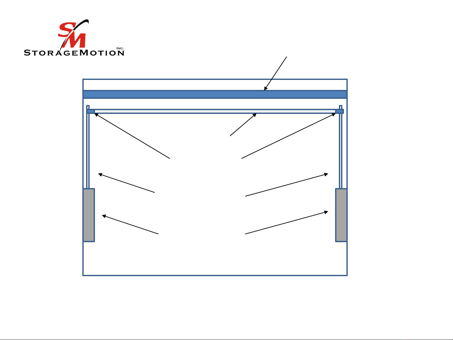
5. Measure the closet opening (see Fig 1 )The metal motor tube needs to be cut 1 1/2 inches less
than the closet opening(inside dimension). See photo 2 for where to hold the measuring tape.
Do not include the motor head when measuring the tube.
6. Insert right side end cap into the metal tube and place white round plastic idler bearing
onto right side end cap. Do not yet mount tube.
7. Mount right side strap with the strap clip and the small machine screw that is supplied. See
photo 3. Drill through the tube with 3/32 bit and attach the strap with the screw so that the
tape on the strap is directly across from the tape on the left side strap. This ensures that the
straps are the same length when lifting the rotating arms. Do not try to drill through the lifting
strap material as this is not necessary. The strap needs to be mounted about ¼ from the right
ed of the tube see Photo 4 ad the “X“ o the tape eeds to be agaist the otor tube so
that the strap clip on the other end is positioned correctly.
CONTACT PHONE - 704 746 3700
4

11 . Ensure that motor tube is parallel with what will be the position of the clothes rod. Motor side of
tube with cord must be on the left side
12. Manually unwrap the straps and attach to the predrilled mounting holes at the end of each
rotating arm using the #6 machine screws and nuts . Do this while the arms are in the complete
down position (Horizontal). Make sure that strap clips are secure and that straps are NOT
twisted and that they line up with the arms. See Fig 4 for strap clip position.
13. If not being hardwired by an electrician, connect the plug to the motor cord. The brass terminal
goes with the black wire and the green screw head goes with the green wire (ground).
14. Plug in the unit . The top button on the transmitter is for UP, the middle button is for STOP, and
the bottom button is for DOWN. Ensure transmitter matches for the motor.
15. Ensure that the lifting straps and the rotating arms are in alignment when the rotating
arms are operating.
8. Mount RIGHT side idler bracket for the motor tube using the 2 #10 screws supplied on right
hand side at the top. Use the sticky foam to assist in placement of the bracket and to reduce
vibration. See Fig 2 and photo 6 for where to position. The motor must be on the left side
for lifting straps to be correct as they must lift from the top of the tube as opposed to the
bottom of the tube
9 Mount LEFT side bracket with 2 # 10 screws provided, Use the sticky foam to assist in
placement of the bracket and to reduce vibration. . See Fig 3 and photo 6 for where to
position.
10. Place tube with motor into square opening in left bracket and then place right side tube into
right side bracket (SEE photo 4 and 5) Make sure that straps are coming from the top of the
tube as opposed to the bottom of the tube.Add the cotter pin to secure the motor in the left
side bracket.
5

17 Test the unit. If lifting straps have different levels of slack, the right or NON motor side strap can
be adjusted by setting a new securing screw position. Ensure that at lower position the
straps have no slack so that straps support the arms rather than just the housing support
the arms.
CONTACT PHONE - 704 746 3700
16 Set the limits Raise black cover to expose very small left and right keys. (see photo 7 and 8)
1. SET DOWN LIMIT. Press left key once then press DOWN button once... Now UP or
DOWN buttons should respond momentarily. Use them to place rotating arm at its
resting point with no slack in straps. Select the stop button (center button) once to
complete the setting
2. SET UP LIMIT. Press left key once then press UP button once…. Now UP or DOWN
buttons should respond momentarily. Use them to locate the rotating arms just
slightly forward (½ inch). Select the stop button (center button) once to complete
the setting.
Notes –a) When entering in the limits settings you only have 5 seconds to BEGIN to command the motor after
pressing the left key. b) In the process of adjustment, any coincidental press to the stop key will be considered
as the limit setting is complete .To restart you must press the LEFT key again. C) LIMITS CAN BE RESET
ANYTIME DURING THE LIFE OF THE PRODUCT.
6

CONTACT PHONE - 704 746 3700
18 Install the wireless wall switch with the hardware provided. If the
Automated WardrobeLiftTM is installed inside a cabinet; please
ensure the wireless, wall switch is mounted inside the cabinet. If
wireless, wall switch is mounted out side the door, the switch may
be activated inadvertently and could, potentially, cause damage to
the cabinet door or the user when the door is opened to access the
unit!
19 See photo 9 and 10 for an example of an enclosure that can used to
conceal the motor tube. The motor tube can also be painted or covered
with wood grain contact paper.
7

PROBLEM
SOLUTION
Rotating arms are not
stopping at proper points
Reset the motor limits using the wireless switch. See motor limit step in the instructions.
Lift does not respond or acts
improperly.
(Be sure to cut power and
reconnect)
Press the reset button using a pin until 1 beep then immediately within 2 seconds press the up or
down button on the switch. Unit should respond . If no response then proceed as follows. Press the
reset button for approx. ten seconds using a pin. Hold until 2 beeps and release Wait another 10
seconds or more then re-associate the motor to a switch by pressing the reset button once for 1 beep
then immediately within 2 seconds press the Up or Down button of the switch.
Switch light out
Check battery
Lift does not go up straight
Adjust the right side strap which is the non motor side strap . Remove the anchor screw and move
the strap material accordingly and then reinsert the screw. See installation instructions. The left side
(Motor Head)strap CANNOT be adjusted.
Lift runs in reverse
Motor head needs to be on left side of tube when facing unit from the front. Lift the black cover on
the switch and press the very small button on the right and hold for 3 seconds. Motor direction
should now be changed
One switch operates two
motors
Press the reset button (very small white button on the motor head) for ten seconds using a pin on the
motor you want to disassociate. Hold until 3 beeps then release. Test all switches to make sure they
will not operate the motor.
Associate the motor to the correct switch by pressing the reset button once then immediately within
2 seconds pressing the Up or Down button of the correct switch. Make sure all other switches are not
activated during this procedure. Set the motor limits.
Trouble Shooting
Reset button
must use pin, small screw
or paperclip to activate.
Beeps are very quiet!
CONTACT PHONE - 704 746 3700

Motor with Tube
Rotating Arms
WARNING –Make sure the arms are mounted above the height of the user when in
the down position
Fig. 1
Mounting Boxes
Clothes Pole
Side Supports
Patent Pending
9

Right hand side view
Distance from the back of the
closet to the clothes rail should
be at least 11 inches .
Motor with Tube Fig. 2
Lifting Strap
back front
Approx 1.5 to 3
in.
Approx
4 to 8
in.
Patent Pending
The motor
tube and
clothes rail can
be mounted as
close to the
ceiling as
desired
Approx 9 inches
10

Left hand side view
Motor with Tube
Motor Cord
Fig. 3
Lifting Strap
backfront
Approx
1.5 to 3 in.
Approx
4 to 8
in.
Wireless
switch location
WARNING –if motor is
mounted too low it is
possible to damage the
unit when setting the
the UP limit as too
much leverage will be
gained
Motor with
Tube
Motor
mounted
TOO low!
Patent Pending
11

Rotating
Arm
Black Metal
Clip
Fig. 4
Machine Screw # 6 -1.5” Long with hex nut
Patent Pending
12

Photo 1
Photo 2
13

Photo 3
Photo 4
Photo 5
Patent Pending
14

Photo 6
See
approximate
location of
motor tube in
relation to
rotating arm
Arm slightly
forward when
in up position
Patent Pending
15

Photo 7 Photo 8
Photo 9 Photo 10
Patent Pending
16
Table of contents
Other Storage Motion Indoor Furnishing manuals
Popular Indoor Furnishing manuals by other brands

PREMIER POLYSTEEL
PREMIER POLYSTEEL Champion 924-507 manual

Acme Furniture
Acme Furniture 62203 Assembly instructions

supremo LEISURE
supremo LEISURE U-shape Modular Set Assembly instruction

Delgard
Delgard DT3248 Installation service

Notável Móveis
Notável Móveis 55004 Assembly instructions

Reliabilt
Reliabilt LS-SW-W2730B manual

Abbyson
Abbyson Kaylen TP-0002ASHB5PDI Assembly instructions & user manual

Forte
Forte STXV37 Assembling Instruction

Performance Health
Performance Health 4850 operating instructions

Nilo
Nilo N33 manual

Featherlite
Featherlite AL60-30 Disassembly

American Standard
American Standard Champion 2018.214 Specification sheet