StorageWorks BA346-K Series User manual

Digital Equipment Corporation
Maynard Massachusetts
Solutions
BA346–K Series
Deskside Expansion Pedestal
User’s Guide
Order Number EK–BA346–UG. A01
This guide describes the procedures for installing, configuring, and maintaining the BA346–K
series deskside expansion pedestal.

ii
March 1995
While Digital believes the information included in this publication is correct as of the date of
publication, it is subject to change without notice.
Digital Equipment Corporation makes no representations that the interconnection of its
products in the manner described in this document will not infringe existing or future patent
rights, nor do the descriptions contained in this document imply the granting of licenses to
make, use, or sell equipment or software in accordance with the description.
FCC ID: AO9-BA346
NOTE: This equipment has been tested and found to comply with the limits for a Class B
digital device, pursuant to Part 15 of the FCC rules. These limits are designed to provide
reasonable protection against harmful interference in a residential installation.
Any changes or modifications made to this equipment may void the user's authority to operate
this equipment.
This equipment generates, uses, and can radiate radio frequency energy and, if not installed
and used in accordance with the instructions, may cause harmful interference to radio
communications. However, there is no guarantee that interference will not occur in a
particular installation. If this equipment does cause harmful interference to radio or television
reception, which can be determined by turning the equipment off and on, the user is
encouraged to try to correct the interference by one or more of the following measures:
Reorient or relocate the receiving antenna
Increase the separation between the equipment and receiver
Connect the equipment into an outlet on a circuit different from that to which the receiver
is connected
Consult the dealer or an experienced radio/TV technician for help
© Digital Equipment Corporation 1995
All Rights Reserved.
Printed in the United States of America.
HSJ, StorageWorks, and the DIGITAL logo are trademarks of Digital Equipment Corporation.
This document was prepared using Microsoft Word for Windows 6.0®

iii
Contents
Chapter 1 Introducing the Deskside Expansion Pedestal
1.1 Product Description.................................................................................................................... 1–1
1.2 Options...................................................................................................................................... 1–2
1.3 Major Components..................................................................................................................... 1–3
1.4 Power......................................................................................................................................... 1–4
1.5 Device Cooling.......................................................................................................................... 1–6
1.6 StorageWorks Building Blocks (SBBs)....................................................................................... 1–7
1.7 Product Specifications................................................................................................................ 1–8
Chapter 2 Installing and Operating the Pedestal
2.1 Installing a Pedestal................................................................................................................... 2–1
2.2 Selecting the Installation Area ................................................................................................... 2–2
2.3 Unpacking a Pedestal................................................................................................................. 2–2
2.4 Packing a Pedestal ..................................................................................................................... 2–4
2.5 Preparing the Pedestal for Operation.......................................................................................... 2–5
2.6 Mounting the Base..................................................................................................................... 2–5
2.7 Installing Options ...................................................................................................................... 2–6
2.8 Configuring the Pedestal............................................................................................................ 2–6
2.9 Installing SBBs.......................................................................................................................... 2–7
2.10 Connecting the SCSI Bus Cables.............................................................................................. 2–8
2.11 Connecting the AC Power Cord ............................................................................................... 2–9
2.12 Operating the Pedestal ............................................................................................................2–10
2.13 Mounting the Door..................................................................................................................2–11
2.14 Replacing a Storage SBB ........................................................................................................2–12
Chapter 3 Configuring a Pedestal
3.1 The Standard Configuration....................................................................................................... 3–1
3.2 SCSI Bus Cables and Accessories............................................................................................... 3–2
3.3 SCSI Buses................................................................................................................................ 3–3
3.4 Internal SCSI Buses................................................................................................................... 3–4
3.5 Removing the Side Panel ........................................................................................................... 3–5
3.6 Setting the Configuration Address.............................................................................................. 3–6
3.7 Device Addresses....................................................................................................................... 3–8
3.8 Completing the Configuration.................................................................................................... 3–8
Glossary
Index

iv
Figures
Figure 1–1 BA346–KB Deskside Expansion Pedestal...................................................................... 1–1
Figure 1–2 BA346 – Rear View...................................................................................................... 1–4
Figure 1–3 DC Power Distribution.................................................................................................. 1–4
Figure 1–4 Pedestal Air Flow.......................................................................................................... 1–6
Figure 1–5 Typical 3.5–Inch SBB................................................................................................... 1–7
Figure 2–1 Pedestal Dimensions ..................................................................................................... 2–1
Figure 2–2 Pedestal Packing ........................................................................................................... 2–3
Figure 2–3 Mounting the Base........................................................................................................ 2–5
Figure 2–4 Standard BA346–KB Configuration.............................................................................. 2–6
Figure 2–5 3.5-Inch SBB ................................................................................................................ 2–7
Figure 2–6 Installing an SBB.......................................................................................................... 2–7
Figure 2–7 BN21K-Series Cable Connectors................................................................................... 2–8
Figure 2–8 BN21L-Series Cable Connectors ................................................................................... 2–8
Figure 2–9 Rear Panel Connectors .................................................................................................. 2–9
Figure 2–10 Power Supply Label..................................................................................................... 2–9
Figure 2–11 Pedestal Power On LED............................................................................................ 2–10
Figure 2–12 Storage SBB Status LEDs.......................................................................................... 2–10
Figure 2–13 Mounting the Door.................................................................................................... 2–11
Figure 3–1 Standard (Shipping) Configuration ............................................................................... 3–1
Figure 3–2 SCSI Cables and Accessories......................................................................................... 3–2
Figure 3–3 BA346–KB SCSI Bus Lengths...................................................................................... 3–4
Figure 3–4 Removing the Side Cover.............................................................................................. 3–5
Figure 3–5 Side Cover Hand Hold................................................................................................... 3–5
Figure 3–6 Address Configuration Jumpers.................................................................................... 3–6
Figure 3–7 BA346–KB Standard Configuration.............................................................................. 3–6
Tables
Table 1–1 Major BA346–K Series Pedestal Components................................................................ 1–3
Table 1–2 Power Supply Specifications........................................................................................... 1–4
Table 1–3 Recommended Country-Specific AC Power Cords.......................................................... 1–5
Table 1–4 BA346–KB Pedestal Specifications................................................................................. 1–8
Table 1–5 Air Flow......................................................................................................................... 1–8
Table 3–1 Standard Configuration Specifications............................................................................ 3–1
Table 3–2 SCSI Bus Accessories..................................................................................................... 3–2
Table 3–3 SCSI Buses and Cables................................................................................................... 3–3
Table 3–4 Determining SCSI Bus Lengths...................................................................................... 3–4
Table 3–5 Standard Configuration Addresses and Slot Addresses.................................................... 3–7

v
Preface
The StorageWorks BA346–K Series Deskside Expansion Pedestal User’s Guide describes the
installation, configuration, and maintenance of this family of pedestal storage arrays.
Intended Audience
This guide is for use by individuals responsible for configuring, installing, and maintaining
pedestals.
Structure
The organization of this guide is as follows:
Chapter 1 This chapter is an introduction to the pedestal that includes product
description, features, StorageWorks building blocks, power, fans, and
product specifications.
Chapter 2 This chapter describes how to install a deskside pedestal and includes:
• Unpacking pedestals
• Selecting the installation area
• Selecting SCSI buses and cables
• Connecting the pedestal to the SCSI controller
• Installing the SBBs
Chapter 3 This chapter contains the following pedestal configuration procedures:
• Connecting the internal SCSI bus Cabling
• Setting the configuration address
• Setting device addresses
Related Documents
The following is a list of other StorageWorks user documents applicable to pedestals.
Document Title Order Number
StorageWorks Solutions BA346–KB Deskside Expansion
Pedestal 5.25-Inch Device Installation Guide EK–346AA–IG
StorageWorks Solutions BA346–KB Deskside Expansion
Pedestal Dual Bus Installation Guide EK–346AB–IG
StorageWorks Solutions Configuration Guide EK–BA350–CG
StorageWorks Solutions SBB User’s Guide EK–SBB35–UG

vi
Documentation Conventions
The documentation conventions in this guide are as follows:
boldface type Boldface type indicates the first instance of terms being defined in the
text, the glossary, or both.
italic type Italic type indicates emphasis and complete publication titles. In the
glossary, italic type indicates cross-references.

Introducing the Deskside Expansion Pedestal 1–1
1
Introducing the Deskside
Expansion Pedestal
This chapter is an introduction to the BA346–KB series deskside expansion pedestal,
commonly referred to as the “pedestal.” This description includes the options, components,
power and cooling requirements, StorageWorks building blocks (SBBs), and specifications.
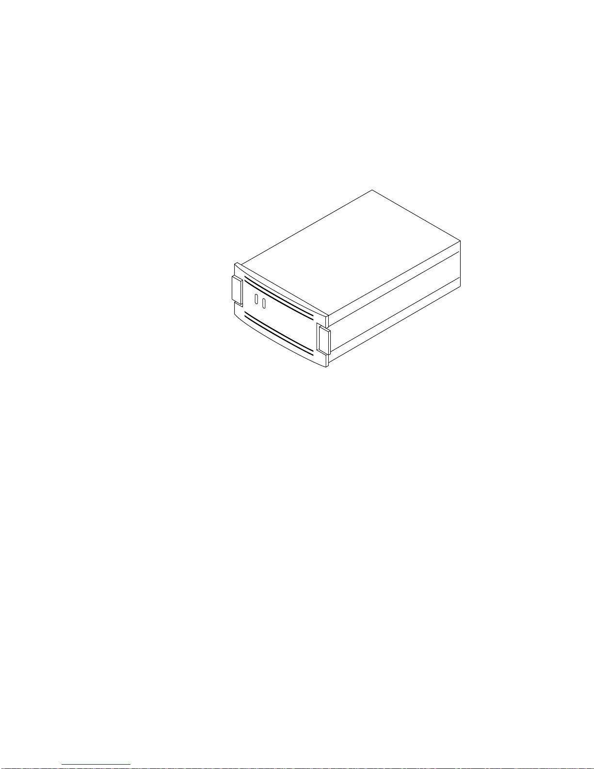
1.1 Product Description
The standard BA346–KB deskside expansion
pedestal (pedestal) shown Figure 1–1 is an
enclosure for creating a user-defined storage array
using the small computer system interface (SCSI)
bus. The following are the features of this
pedestal:
• Single-ended, 8-bit or 16-bit, SCSI–2 bus
• Capacity of seven, 3.5-inch SBBs
• 68-pin, high-density input and output
connectors
• ac power supply (switch selectable input
50 to 60 Hz, 115 to 240 V ac)
• Cooling fan
• Jumper selectable SCSI address configurations
• Active SCSI bus termination
To expand the number of devices on a 16-bit SCSI
bus you can interconnect the pedestals providing
you do not exceed the SCSI bus length limitations
listed in Chapter 3.
Figure 1–1 BA346–KB Deskside Expansion
Pedestal
CXO-4552A-MC

1–2 Introducing the Deskside Expansion Pedestal
1.2 Options
You can install the following options in a pedestal either individually or in combination:
BA35X–AA 5.25-Inch Device Option Kit
This kit contains a modular carrier, the cables, and the mounting hardware for installing
either two half-height, or one full-height, 5.25-inch storage device in the top of the
pedestal. This option increases the total number of devices on a 16-bit bus to nine.
See StorageWorks Solutions BA346–KB Deskside Expansion Pedestal 5.25-Inch Device
Installation Guide for detailed information about installing and configuring this option.
BA35X–AB Dual-Bus Option Kit
With the cables and connectors in the dual bus option kit you can split the backplane bus
into two buses—a four device bus and a three device bus. When used in conjunction with
the 5.25-inch option kit, you can have a six device bus and a three device bus in the same
pedestal.
See StorageWorks Solutions BA346–KB Deskside Expansion Pedestal Dual Bus
Installation Guide for detailed information about installing and configuring this option.
BA35X-VB Stability Option Kit
This kit includes a base that improves the stability of the pedestal. The procedures for
installing the base are described in Section 2.6.
BA35X–YA Factory Configuration Option
When you select this option, the factory:
• Sets the configuration addresses (jumpers W1-W3) as the user specifies.
• Installs the SBBs in the slots the user specifies.
• Sets the SCSI device addresses.
• Installs the 5.25-inch modular carrier option and devices.
• Installs the dual bus option.
• Configures the internal SCSI bus.
• Includes, but does not mount, the pedestal door.

Introducing the Deskside Expansion Pedestal 1–3
1.3 Major Components
The user is responsible for providing the following components, which are available through
your Digital account representative:
• AC power cord with NEMA 15 connector (see Table 1–3)
• Storage Devices—5.25-inch devices and 3.5-inch SBBs
• SCSI cables (BN21K or BN21L)
Table 1–1 lists the major pedestal components supplied with the basic unit and each option.
Table 1–1 Major BA346–K Series Pedestal Components
Component BA346–KB BA35X–AA BA35X–AB BA35X–VB
Base, Pedestal 0 0 0 1
Cable, Adapter (68-pin to 50-pin) 0 1 0 0
Cable, Input/Output 1 0 3 0
Cable, Input/Output, 5.25-inch device 0 1 0 0
Cable, Jumper 1 0 0 0
Door 1 0 0 0
Enclosure 1 0 0 0
Terminator 1 0 1 0

1–4 Introducing the Deskside Expansion Pedestal
1.4 Power
The ac power supply (switch-selectable 115 V ac or 230 V ac input), is located in the rear of
the pedestal as shown in Figure 1–2. Figure 1–3 shows the internal dc power distribution,
Table 1–2 lists the power supply specifications, and Table 1–3 lists the country specific ac
power cords.
Table 1–2 Power Supply Specifications
Specification Rating
Power 200 W
Nominal Output Voltages +5 V dc @ 20 A
+12 V dc @ 8 A
Figure 1–2 BA346 – Rear View
CXO-4479A-MC
AC INPUT
SWITCH
AC INPUT
CONNECTOR
Figure 1–3 DC Power Distribution
CXO-4480A-MC
J10
J11
J16
J17
J12
J13

Introducing the Deskside Expansion Pedestal 1–5
Table 1–3 Recommended Country-Specific AC Power Cords
Length Digital
Country Voltage Amps Connector Type Plug Type M Ft Order No.
Australia 250 V ac 10 A IEC 320 C13, C14 AS3112 – 1981 2.5 8.2 BN19H–2E
Central Europe 250 V ac 10 A IEC 320 C13, C14 CEE 7/7 (Schuko) 2.5 8.2 BN19C–2E
Denmark 250 V ac 10 A IEC 320 C13, C14 Afsnit 107 2.5 8.2 BN19K–2E
India 250 V ac 10 A IEC 320 C13, C14 BS 546 2.5 8.2 BN19S–2E
Ireland 250 V ac 10 A IEC 320 C13, C14 BS 1363 2.5 8.2 BN19A–2E
Israel 250 V ac 10 A IEC 320 C13, C14 SI 32 2.5 8.2 BN18L–2E
Italy 250 V ac 10 A IEC 320 C13, C14 CEI 213–16/VII 2.5 8.2 BN19M–2E
Japan 125 V ac 15 A IEC 320 C13, C14 NEMA 5–15 3.0 9.8 BN27S–03
New Zealand 250 V ac 10 A IEC 320 C13, C14 AS3112 – 1981 2.5 8.2 BN19H–2E
South Africa 250 V ac 10 A IEC 320 C13, C14 BS 546 2.5 8.2 BN19S–2E
Switzerland 250 V ac 10 A IEC 320 C13, C14 SEV 1011 2.5 8.2 E0–BN19H–2E
United Kingdom 250 V ac 10 A IEC 320 C13, C14 BS 3163 2.5 8.2 BN19A–2E
United States 125 V ac 15 A IEC 320 C13, C14 NEMA 5–15 3.0 9.8 BN27S–03

1–6 Introducing the Deskside Expansion Pedestal
1.5 Device Cooling
Proper device operation requires cooling. The two fans in the pedestal and in the power
supply.
• The fan mounted on the rear of the pedestal cools the storage devices.
• The power supply internal fan cools the 5.25-inch devices and the power supply.
As shown in Figure 1–4, both fans draw air through the front of the pedestal, through the
storage devices, and exhaust it out the rear.
CAUTION
Blocking or restricting the intake or output air flow can cause overheating.
Therefore, leave a clear space of at least 0.3 m (1 ft) in front and behind the
pedestal.
Figure 1–4 Pedestal Air Flow
CXO-4481A-MC
Introducing the Deskside Expansion Pedestal 1–7
1.6 StorageWorks Building Blocks (SBBs)
The pedestal supports only 3.5-inch form-factor storage devices in a modular carrier, an SBB
(see Figure 1–5). The StorageWorks Solutions Configuration Guide lists the pedestal
compatible 3.5–inch storage devices.
Figure 1–5 Typical 3.5–Inch SBB
CXO-4379A-MC
The following primary factors determine the compatible storage devices:
• The SCSI controller must support all the storage devices.
• The SCSI controller must support all the combinations of storage devices on the bus.
• The pedestal does not support 5.25-inch SBBs.
• The pedestal does support 5.25-inch devices mounted in the 5.25-inch modular carrier
option (BA35X–AA).
1–8 Introducing the Deskside Expansion Pedestal
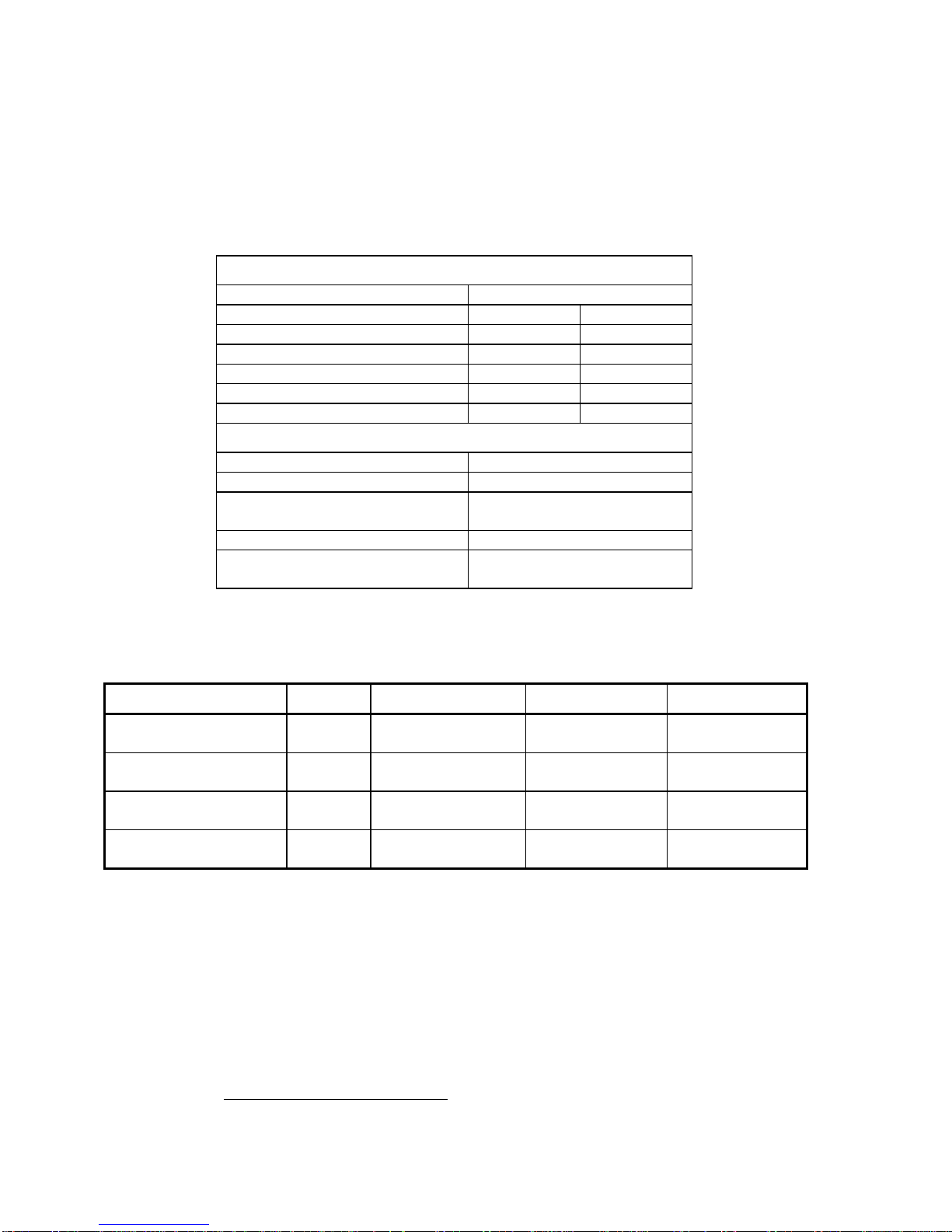
1.7 Product Specifications
Table 1–4 lists the basic product specifications.
Table 1–4 BA346–KB Pedestal Specifications
Physical Specifications
Item Dimension
Height 533 mm 21 in
Width 203 mm 8 in
Depth 483 mm 19 in
Rear clearance (air exhaust) 305 mm 12 in
Front clearance (door opening) 305 mm 12 in
Weight (no devices) 17 kg 37 lb
Power Item Rating
Total Power 200 W
Nominal Output Voltages +5 V dc @ 20 A
+12 V dc @ 8 A
Device startup*4 second interval (minimum)
Power available to 5.25-inch devices +5 V dc @ 20 A
+12 V dc @ 8 A
Table 1–5 lists the air flow through the pedestal under test conditions with the door open.
Table 1–5 Air Flow
Device Qty Slots Measured at Volume (CFM)
5.25-inch devices
3.5-inch devices 2
7All filled Both 5.25-inch slots 2.86
5.25-inch devices
3.5-inch devices 2
6Slot 7 (bottom) empty Both 5.25-inch slots 2.74
5.25-inch devices
3.5-inch devices 2
7All filled RZ28B in Slot 4 2.34
5.25-inch devices
3.5-inch devices 2
6Slot 7 (bottom) empty RZ28B in Slot 4 1.79
*This is the time required before a storage device is ready to transfer data. For example, the time it takes a disk to spin
up, a tape drive to tension, and so forth.
Installing and Operating a Pedestal 2–1
2
Installing and
Operating a Pedestal
This chapter describes the procedures for installing and operating a BA346–KB series
deskside expansion pedestal. Subjects addressed include selecting the installation area,
unpacking the pedestal, installing storage devices, connecting cables, and checking pedestal
operation
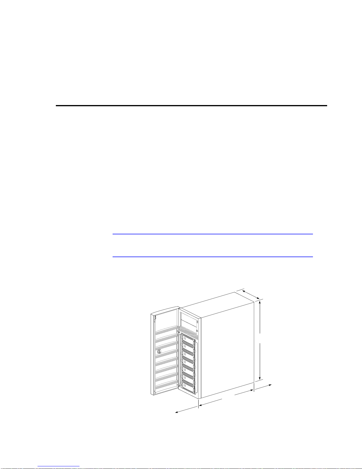
2.1 Installing a Pedestal
You can usually install the pedestal within 2 meters (6.6 feet) of the SCSI controller and next
to an ac receptacle. A desktop, a table, or the floor are acceptable installation locations
Figure 2–1 shows the minimum pedestal dimensions.
CAUTION
Blocking or restricting the input or output air flow can cause overheating.
Therefore, leave a clear space of at least 0.3 m (1 ft) at both the front and rear of
the pedestal.
Figure 2–1 Pedestal Dimensions
CXO-4553A-MC
533 mm
(21 in)
203 mm
(8 in)
483 mm
(19 in)
AIR FLOW
305 MM
(12 in)
FRONT DOOR
203 mm
(10 in)

`2–2 Installing and Operating a Pedestal
2.2 Selecting the Installation Area
The location of the pedestal depends upon the availability of ac power and the distance to the
SCSI controller. SCSI bus length is critical to selecting the installation area. Therefore,
before selecting the installation area, read Section 3.3.
CAUTION
Blocking or restricting the input or output air flow can cause overheating.
Therefore, leave a clear space of at least 0.31 m (1 ft) at both the front and rear of
the pedestal.
2.3 Unpacking a Pedestal
The shipping containers provide maximum protection for the pedestal and all components.
Digital recommends that you unpack the pedestal in the installation.
WARNING
To prevent personal injury always use two people to pack, unpack, or move the
pedestal in the shipping container.
Refer to Figure 2–2 and complete the following procedure to unpack a pedestal:
1. Orient the shipping container as shown.
2. Open the shipping container. Slide the pedestal and the packing material on to the floor .
3. Remove the documentation package.
4. Remove the top foam blocks.
5. Remove the door.
6. Remove the pedestal.
7. Replace all packing material, including plastic bags, in shipping container.
8. Store the shipping container for future use.
Note
Retain all packing materials for future use. Shipping pedestals without the proper
packing materials can cause damage to the pedestal.

Installing and Operating a Pedestal 2–3
Figure 2–2 Pedestal Packing
SHIPPING
CARTON
USER
DOCUMENTATION
FOAM
BLOCK
BA346-KB
DOOR WITH
SHIPPING
SLEEVE
CXO-4633A-MC

`2–4 Installing and Operating a Pedestal
2.4 Packing a Pedestal
WARNING
To prevent personal injury always use two people to pack, unpack, or move the
pedestal in the shipping container.
Complete the following procedures to pack a pedestal for shipping:
CAUTION
To prevent damage to the pedestal, you must use the approved packing materials
and pack the pedestal as described in this procedure
1. Place the components in the plastic bags.
2. Remove the packing material from the shipping container.
3. Open the shipping container and orient it as shown in Figure 2–2.
4. Remove the door and all external cables from the pedestal.
5. Place the two bottom foam blocks on the shipping container .lid
6. Insert the pedestal in the bottom foam blocks.
7. Insert the door into its shipping sleeve.
8. Insert the door into the foam blocks.
9. Place the top foam blocks on top of the pedestal and door.
10. Place the cardboard tray on top of the foam block.
11. Slide the pedestal and shipping materials into the carton.
12. Seal the carton.

Installing and Operating a Pedestal 2–5
2.5 Preparing the Pedestal for Operation
Preparing the pedestal for operation involves the following procedures:
• Mounting the base (BA35X–VB option)
• Installing options (BA35X–AA, BA35X–AB)
• Configuring the pedestal (optional)
• Installing the storage devices
• Connecting the power and SCSI bus cables
• Checking the pedestal and its components for proper operation
• Mounting the door
2.6 Mounting the Base
Complete the following procedure to mount the base (BA35X–VB option):
1. Place the pedestal on its top.
2. Align the base with bottom of the pedestal (see Figure 2–3).
3. Install the four, hex-head 6-32 screws through the base into the pedestal.
4. Set the pedestal on the base and continue the installation process.
Figure 2–3 Mounting the Base
CXO-4632A-MC
PEDESTAL
(BOTTOM)
BASE

`2–6 Installing and Operating a Pedestal
2.7 Installing Options
Complete the procedures described in the individual option installation guides.
2.8 Configuring the Pedestal
The pedestal is factory-configured as a single SCSI bus with the device addresses shown in
Figure 2–4. You can use the procedures in Chapter 3 to change the configuration.
Figure 2–4 Standard BA346–KB Configuration
CXO-4550A-MC
J10
INPUT
CABLE
J11
J16
J17
JUMPER
CABLE
TERMINATOR
STANDARD
CONFIGURATION
J18
IN
OUT
W1 W2 W3
SCSI ADDRESS 0
SCSI ADDRESS 1
SCSI ADDRESS 2
SCSI ADDRESS 3
SCSI ADDRESS 4
SCSI ADDRESS 5
SCSI ADDRESS 6
This manual suits for next models
4
Table of contents
Other StorageWorks Enclosure manuals


