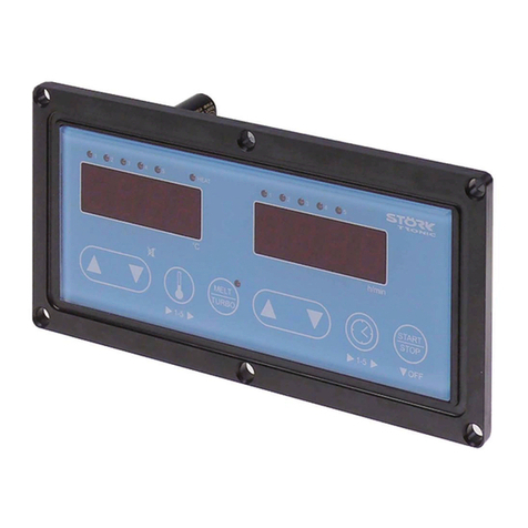
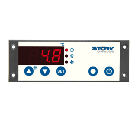
STORK TRONIC ST501-QE1TA.09 User manual

ST501-QE1TA.09
Deep-frying controller
Order number 900219.092
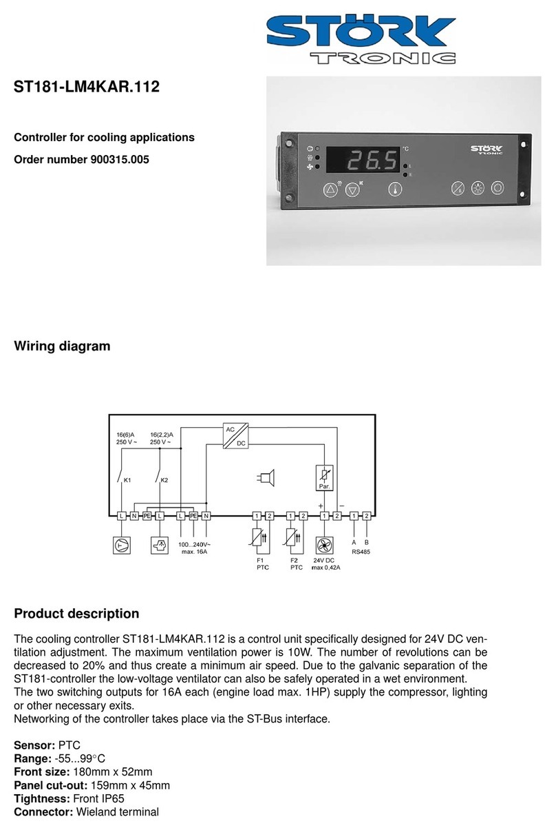
Wiring diagram
Product description
The controller ST501-QE1TA.09 fulfils the function of a temperature controller and is cut to the use
with deep-fryers. It has a 4-digit LED display, 6 keys, 2 relays and a switching input. The different
temperature setpoints and timer defaults can be parametered directly by the keys.
Sensor: multi-resistance input
Range: dependent on the type of sensor
Front size: 106mm x 68mm
Panel cut-out: 87,5mm x 56,5mm
Tightness: front IP64
Connector: screw terminal
1

2

SOFTWARE .09
General information
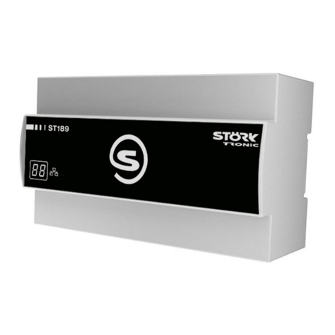
The unit is made of a service board and a separate power board which are linked with a ribbon
cable. Both parts form a complete installation unit. All outputs and inputs are connected on the
back of the power board. The unit fulfils the function of a temperature controller with timer function
and is cut to the use with deep-fryers.
On the front of the unit has a 4-digit 7-segment LED display, 6 keys and 6 LEDs. 3 LEDs identify
the selected temperature setpoint relevant for the regulation (“temperature 1, 2, 3”), 1 LED shows
the status of the timer (“time 1”) and the remaining 2 LEDs indicate the heating mode (“TURBO”)
and the present status of the control output (“HEAT”). During the timer expires the LED “time 1”
flashes, during careful heating the LED “TURBO” flashes. If the LED “TURBO” is off the unit
regulates with PID characteristics and approaches the setpoint preventing extreme oscillating. If
the LED “TURBO” lights up permanently thermostatic regulation and therefore the utmost heat
supply is active.
A temperature sensor is connected to measure the actual value. Be means of parameter it is
possible to select among Pt100, Pt1000 and PTC as sensor type without circuitry adaptations. Two
switching inputs – if available – permit the start of the timer with an external switching key and the
activation of a setpoint reduction, which is indicated by a flashing point on the right side of the
display. The function of the switching inputs can be deactivated with parameters.
The output relays are two change-over contacts. The functions “heating”, “control contact 2” or
“alarm” can be assigned to each output, even the deactivation of a output is possible.
The controller has the possibility of a particularly careful heating in case the deep fryer fat is not yet
melted. This retarded heating process (Melt-function) is always activated after switching no the unit
and ends if an adjustable limit value below the setpoint is reached. If the fat is evidently melted you
can switch to accelerated heating by pressing the “TURBO” key even before the limit value is
reached. During cooling the turbo-mode remains active until the temperature falls below 50 °C.
Then the reloading of solid fat is assumed and the controller switches back to reduced heating
automatically. The reduced heating mode can be deactivated.
Two adjustable limit values provide a temperature alarm relative to the control setpoint. Boundary
and range alarm as well as relative and absolute limit values are possible.
In these alarm cases the control process continues. An internal buzzer provides an
acknowledgeable alarm signal..
An operating time recording monitors the fat temperature and counts the operating hours with
actual values above an adjustable limit value. An alarm message can be activated or a regulation
blocking takes place (if activated) to force replacing the deep fryer fat. A reset is only possible in
alarm or blocking condition, in addition temperature must fall below a further adjustable limit value.
If a regular exchange of the fat is guaranteed otherwise, an unconditional reset of the fat operating
time can be enabled by means of parameters.

Adjustment options
Key 1: UP
Pressing this key you can increase the parameter or parameter value or scroll the
parameter list.
Key 2: DOWN
Pressing this key you can decrease the parameter or parameter value or scroll the
parameter list. At alarm the buzzer function can be switched off with this key. Any fat
alarm message can be switched off as well, however the internal alarm condition
remains active and the alarm restarts at each unit start.
Key 3: selection of temperature setpoint
With this key the temperature setpoint relevant for the regulation is selected. If
previously the timer display is active the controller at first switches to temperature
display with the first key pressing. With parameters you can determine if the respective
setpoint is still selected after switching of the mains voltage or if one of the setpoints
S1-S3 is selected.
Key 4: selection of timer setpoint
With this key the timer setpoint is selected and the LED of the timer lights up. The value
shows up in the display for 5 seconds and can be adjusted with the UP and DOWN key.
If none f the key is pressed the display automatically shows the temperature again, the
timer LED goes out. If the key is pressed for 2 seconds the timer is started and the LED
flashes. The remaining time is shown only for a moment but the flashing LED indicates
the elapsing timer. A permanent display of the remaining time can be activated with
parameters, then the LED of the timer is permanently on. If the key is pressed for 5
seconds the timer is stopped and the display indicated “0:00”.
Key 3+4: setpoint reduction
Simultaneously pressing these two keys activates the setpoint reduction, in addition
with the UP and DOWN key it can be adjusted. Please note that the setpoint reduction
is only effective in case of a closed switching input. In case of an activated setpoint
reduction a point flashes no the right side of the display. Setpoint reduction is only
possible with controllers with switching input(s).
Key 5: MELT/TURBO
With this toggle key one can choose between reduced and accelerated heating mode.
Together with the thermostatic function the turbo-heating offers a further increase of
heat supply. After switching on the controller the turbo-heating always is deactivated.
The key is ineffective if the reduced heating mode is deactivated or in some
temperature ranges if no PID characteristic is selected. See below for all choice
options.
Key 6: ON/OFF
If this key is pressed for 1 second the controller switches to standby mode, the display
shows “OFF” or “AUS” and a started timer cycle is aborted. After switching mains on the
controller always is in standby mode. The key can be deactivated, then the controller is
switched on with mains voltage.

Key 5+6: Reset operating time recording
By a simultaneous pressing of these keys a reset of the time recording is caused, the
display indicates “rES”. After releasing the keys the alarm message "OIL" is deleted and
if necessary the regulation blocking is cancelled. The accumulated operating time is
deleted.
Note that a reset is only possible in case of an alarm message or blocking and below
the adjusted temperature limit value. This is to prevent the user from operating the
deep-fryers without replacing the fat. However an unconditional reset can be enabled
by means of parameters.

Switching mode of the key MELT/TURBO
Status display with LED TURBO
flashing = Melt-function
off = PID-control
on = Turbo-control
1. A6 = 1, A88 = 1
Melt-function and PID-control are activated. The toggle mode of the key depends on the
temperature range and if the limit P37 once has been reached. The switching options are shows in
the graph below:
2. A6 = 0, A88 = 1
The melt-function is activated and the PID control deactivated. The controller always operates in
thermostatic mode (i.e. turbo-heating) after the heating phase. In each case where switching
PID/Turbo was possible the key now is ineffective.
3. A6 = 1, A88 = 0
The melt-function is deactivated and the PID control activated. The controller has no reduced
heating phase below the limit P37. In each case where switching Melt/Turbo was possible it is now
possible to switch between PID/Turbo.
4. A6 = 0, A88 = 0
Both the melt-function and the PID control are deactivated. The controller has no reduced heating
phase below the limit P37 and it is set to thermostatic characteristics (i.e. turbo-heating) in all
temperature ranges. There are no switching options, the key is ineffective.
180 °C
150 °C
50 °C
Setpoint
End of reduced
heating (P37)
Switch back threshold
Melt
Turbo
Melt
Turbo
Melt
Turbo
Pid
Turbo
Pid
Turbo
Pid
Turbo
Pid
Turbo
Pid
Turbo

First control level:
Adjustment of the main setpoints and the setpoint reduction
The main setpoint is indicated by pressing the UP together with the DOWN key, after a short
release time it can be adjusted with these keys.
The setpoint reduction is indicated by pressing keys 3+4 together. By additionally pressing the UP
or DOWN key it can be adjusted.
Para-
meter
Function description
Adjustment range
Standard
setting
Custom
setting
S1,
S2,
S3
Temperature setpoints
(the currently selected setpoint is
indicated and/or adjusted)
P4...P5 °C 170 °C
160 °C
100 °C
T1, Timer setpoint 0:00 … 99:99 Min. 1:11 Min.
S1' Setpoint reduction
(is added to the main setpoint in
case of closed switching input
E2)
-99...99.0 K -5.0 K

Second control level (P-parameters):
Adjustment of control parameters
The one-finger-setup of the setpoint adjustment requires an exactly simultaneous pressing of the
UP and DOWN key for at least 4 seconds to open a parameter list containing control parameters.
(If by mistake the setpoint adjustment is released a new attempt is possible after 5 seconds.)
With the UP and DOWN keys the list can be scrolled in both directions.
Pressing key 3 will give you the value of the respective parameter. Pressing also the UP or DOWN
key at the same time the value can be adjusted.
Return to the initial position takes place automatically if no key is pressed for 60 seconds.
Para-
meter
Function description
Adjustment range
Standard
setting
Custom
setting
P1
Setpoint 2 or
DeltaW
-99.9...999°C
-99.9...99.9 K
0.0 °C
P2
Hysteresis contact K1
1...99 K
1.0 K
P3
Hysteresis contact K2
1...99 K
1.0 K
P4
Control range limitation – minimum
setpoint
-99.9...P5°C
0.0°C
P5
Control range limitation – maximum
setpoint
P4...999.9°C
205 °C
P7
Proportional band
1...100 K
10.0 K
P8
Reset time Tn (I-factor)
0...999 sec.
(0 sec. = inactive)
0 sec.
P9
Lead time Tv (D-factor)
0...999 sec.
(0 sec. = inactive)
0 sec.
P10*
Cycle time Tp
2...100 sec.
10 sec.
P19
Key-lock
(only for setpoint setting)
0: no key-lock
1: key-lock
0
P20
Indication of actual value sensor F1
-----
-----
P21
Actual value correction sensor F1
-20...20.0 K
0.0 K
P24
Switch off delay
Control contact 1
0.0...99.0 sec.
0.0 sec.
P25
Temperature limit for fat operating
time
0.0...999 °C
999 °C
P26
Fat operating time until fat alarm
message
0...99 h
(0 h = inactive)
0 h
P27
Fat operating time until regulation
blocking
0...99 h
(0 Std. = inactive)
0 h
P28
Indication of fat operating time
-----
-----
P29
Temperature limit for reset of fat
operating times
-99...999 °C
100 °C
P30
Lower alarm value
-99,9°C/K...P31
-40 °C
P31
Upper alarm value
P30...999 °C/K
208 °C
P32
Hysteresis alarm circuit
0,1...99.9 K
1.0 K
P35
“Reduced heating” – heating on
1...255 sec.
60 sec.
P36
“Reduced heating” – heating off
1...255 sec.
90 sec.
P37
End of “reduced heating” below
setpoint
-99...0.0 K
-30 K
* The PID-control suppressed switch-on times below 0.1 seconds.

Parameter description:
P1: Setpoint / DeltaW for control circuit 2
Adjusting the setpoint of control circuit 2.
If A5=1, the setpoints for control circuit 1 and 2 are linked with one another via switching difference
DeltaW, which can be adjusted with P1. (operation with DeltaW)
The following applies: setpoint thermostat 2 = setpoint control circuit 1 + delta W2.
This difference can take positive or negative values. Thus, a leading or following contact can be
realised.
P2: Hysteresis contact K1
P3: Hysteresis contact K2
The hysteresis can be set symmetrically or one-sided at the setpoint (see A40, A41).
At one-sided setting, the hysteresis works downward with heating contact and upward with cooling
contact. At symmetrical hysteresis, half of the hysteresis’ value is effective below and half of the
value above the switching point (see fig. 1 and 2).
Fig. 1: Heating controller, one-sided hysteresis Fig. 2: Cooling controller, symmetrical
hysteresis
The hysteresis is only effective if thermostatic mode is enabled, in case of PID characteristic it is
ineffective.
P4: Control range limitation – minimum setpoint
P5: Control range limitation – maximum setpoint
The adjustment range of the setpoint can be limited in both directions. This is to prevent the end
user of a unit from setting inadmissible or dangerous setpoints.
P7: Proportional band at PID regulation
The proportional part works in such a way that with approximation of the actual value to the
setpoint the variable is reduced linearly from +-100% to 0%.
P8: Reset time Tn (Integral-portion)
The proportional controller as such has a remaining deviation of the actual value from the setpoint.
The integral portion provides for a complete compensation of this offset
The reset time is a measure for the period of time needed to adjust a remaining temperature
deviation of the size of the proportional range.
If a small reset time is set, a fast post-adjustment will take place. At a too small reset time,
however, the system may tend to vibrate

P9: Lead time Tv (Differential-portion)
The differential portion dampens temperature changes. If a long lead time Tv is set, damping is
strong. At too long lead time, however, the system may tend to vibrate. At setting 0 the values are
ineffective. It is therefore possible to realise a pure PI or PD regulation.
P10: Cycle time Tp
The cycle time is the time, in which the control output runs through one switching period, i.e. once
switched out and once switched on. The smaller the cycle time, the faster the regulation. By
consequence, however, there is also an increased switching frequency of the exit, which can lead
to rapid wear of relay contacts. For very fast control ways with the respective high switching
frequency a voltage output is therefore of advantage.
P19: Key-lock
The key-lock allows blocking of the control keys. In locked condition parameter adjustments with
keys is not possible. At the attempt to adjust the parameters despite key-lock the message "==="
appears in the display.
P20: Actual value sensor F1
The here indicated temperature presents the sum of actual measured value of sensor F1 and the
actual value correction according to parameter P21.
P21: Actual value correction
This parameter allows the correction of actual value deviations caused for example by sensor
tolerances or extremely long sensor lines. The regulation measure value is increased or decreased
by the here adjusted value.
P25: Temperature limit for fat operating time
Above this temperature the internal recording of fat operating time is started. If the values of P26
and P27 are exceeded the alarm message and/or regulation blocking is activated.
P26: Fat operating time until fat alarm message
After this time period an alarm message requests the exchange of the deep-frying fat. The display
indicates flashing “OIL”. With P26=0 this function is deactivated and no alarm message occurs.
Regulation blocking is still possible. The alarm message appears each time the operating time limit
is reached and with every “mains-on” or “standby-on”, it can be cancelled with the DOWN key.
A reset afer an alarm message and cooled down deep-fryer is possible as well.
Then the fat is to be changed as the accumulated operating time is deleted.
P27: Fat operating time until regulation blocking
After this time period an regulation blocking requests the exchange of the deep-frying fat. A reset
with coold down deep-fryer has to be carried out to release the blocking and delete the operating
time. With P27=0 this function is deactivated and no blocking occurs. Fat alarm message is still
possible. With P26=0 and P27=0 no operating time recording takes place.
P28: Indication of fat operating time
The operating hours counter determines the actual operating time of the fat. The time couter runs if
the fat temperature is above the value of P25 (only full hours are couted). By pressing the SET key
the actual operating time is indicated. The operating time counter can be set to Zero by a reset
(pressing the MELT/TURBO key together with the START/STOP key for 10 seconds).
P29: Temperature limit for reset of fat operating times
To allow a reset of alarm message, regulation blocking and accumulated operating time the fat
must be cooled down This paramter determines the temperature value the fat must be cooled
down to this value. This is to prevent the user from operating the deep-fryer without replacing the
fat. If a reset after warning message or blocking must be possible independently of the actual
temperature P29 must be set to 999°C. With A85=1 the reset can be permitted unconditionally.
P30: Lower alarm value
P31: Upper alarm value
The exit alarm is a boundary alarm or a range alarm with one-sided or symmetrical hysteresis (see
parameter P32 and A42). Both at the boundary alarm and the range alarm, limit values can be
relative, i.e. going along with the setpoint, or absolute, i.e. independent of the setpoint. The
operation mode is set with parameter A30. If, in case of boundary alarm and only one switching
point is required the not used second switching point should be adjusted to a value above or below
the operating range of the controller.
Boundary alarm function (see fig. 5):
The alarm contact is closed if the process
temperature is above the upper or below the
lower boundary value.
Fig. 5: Boundary alarm, rel. boundaries
Range alarm function (see fig. 6):
Opposite switching behaviour to the boundary
value alarm. The alarm contact is closed if
the actual value remains between the
boundary values.
Fig 6: Range alarm, abs. boundaries
P32: Hysteresis alarm contact
The hysteresis can be set symmetrically or one-sided at the adjusted limit values. (see A42). It
becomes effective depending on alarm definition. At one-sided setting and boundary alarm the
hysteresis is effective above the lower and below the upper limit value. At one-sided setting and
range alarm the hysteresis is effective above the upper and below the lower limit value. At
symmetrical hysteresis, half of the hysteresis’ value is effective below and half of the value above
the switching point.
P35: “Reduced heating” – heating on
This parameter determines the period of the “reduced heating” process where heating in enabled.
The sequential switching of the output relay serves for a careful heating if the fat is not yet melted.
P36: “Reduced heating” – heating off
This parameter determines the period of the “reduced heating” process where heating in disabled.
P37: End of “reduced heating” below setpoint
This parameter provides a premature cancel of the “reduced heating” process below the setpoint
(process ends at [setpoint+P37]°C).
If the sequential heating is supposed to continue until the setpoint parameter P37 is to be set to
0,0K.

Third control level, (A parameters):
Setting of control parameters
Access to the third control level is granted when selecting the last P-parameter on the second
control level. Continue to press the UP key for approximately 10 seconds until “PA” appears.
Continue to press the UP key and additionally press the DOWN key for about 4 seconds and the
first A-parameter of the third control level is indicated.
With the keys UP and DOWN you can scroll the list in both directions. Pressing key 3 will give you
the value of the respective parameter. By pressing the UP or DOWN key at the same time the
value can be adjusted.
Return to the initial position takes place automatically, if no key is pressed for 60 seconds, or by
simultaneously pressing the UP and DOWN key for approx. 4 seconds.
Para-
meter
Function description
Adjustment range
Standard
setting
Custom
setting
A1
Switch mode contact K1
0: heating contact
1: cooling contact
0
A2
Switch mode contact K2
0: heating contact
1: cooling contact
0
A3
Function of contact K1 at
sensor error
0: relay off
1: relay on
0
A4
Function of contact K2 at
sensor error
0: relay off
1: relay on
0
A5
Selection setpoint 2 or
DeltaW
0: operation with setpoint 2
1: operation with DeltaW
0
A6
Control characteristics
contact K1
0: thermostatic
1: PID
0
A8
Display mode
0: integrals
1: resolution 0.5 K
2: resolution 0.1 K
0
A9
Remaining time display
0: no remaining time indicated
1: remaining time is indicated
0
A10
Selection extended frying
time
0: fixed time
1...20: flexible time
0
A11
Buzzer in case of alarm
message "OIL"
0: no buzzer
1: buzzer
0
A12
Buzzer duration after timer
ends
1...60 sec.
3 sec.
A19
Parameter lock
0: no lock
1: A-parameter locked
2: A- and P-parameter locked
0
A30
Function alarm exit
0:Boundary alarm, relative
1:Boundary alarm, absolute
2:Range alarm, relative
3:Range alarm, absolute
4:Boundary alarm, relative
inverted alarm contact
5:Boundary alarm, absolute
inverted alarm contact
6:Range alarm, relative
inverted alarm contact
7:Range alarm, absolute
inverted alarm contact
1

Para-
meter
Function description
Adjustment range
Standard
setting
Custom
setting
A31
Special function at
boundary alarm
0: no special function
1: flashing display
2: buzzer
3: flashing display and buzzer
4: like 3, buzzer can be cancelled
4
A32
Setpoint display
0: display shows actual value
1: display shows setpoint S1 (S1‘)
0
A33
Switching input E1 (if
available)
0: not active
1: timer start possible
0
A34
Switching input E2 (if
available)
0: not active
1: setpoint reduction possible
(S1' relative to S1)
0
A40
Hysteresis mode contact
K1
0: symmetrically
1: one-sided
1
A41
Hysteresis mode contact
K2
0: symmetrically
1: one-sided
1
A51
Minimum action time
contact K1 „Off“
0.0...99.0 sec.
0.0 sec.
A56
Alarm suppression after
“mains on” / ”standby-on”
0…60 min.
0 min.
A60
Sensor type
11: Pt100 2-wire
21: PTC
22: Pt1000 2-wire.
11
A70
Software filter
1: not active, or else
2…32: average value with 2…32
measuring values
2
A80
Temperature scale
0: Fahrenheit (“AUS”)
1: Celsius (“AUS”)
2: Fahrenheit (“OFF”)
3: Celsius (“OFF”)
3
A85
Reset mode of fat operation
time 0: reset after alarm message or
blocking and cool down
1: reset unconditionally
1
A86
Key delay for standby-key
0...100 (x 0.1 sec.)
10
(=1 sec.)
A87
Standby-function with key
On/Off
0: no function
1: standby function
1
A88
Reduced heating
0: not active, Turbo heating
1: active
1
A89
Initial setpoint selection
after mains on and/or
standby
0: same as before
1: S1
2: S2
3: S3
3
A90
Output connection relay K1
0: no connection
1: connection to contact K1
2: connection to contact K2
3: connection to alarm contact
1

Para-
meter
Function description
Adjustment range
Standard
setting
Custom
setting
A91
Output connection relay K2
0: no connection
1: connection to contact K1
2: connection to contact K2
3: connection to alarm contact
4: on if standby-on
5: on if timer runs
2
Pro
Program version
-----
-----
Parameter description:
The following values can change the equipment characteristics
and are therefore to be set with utmost care.
A1: Switch mode contact K1
A2: Switch mode contact K2
The switch mode for the relays, i.e. cooling or heating function, can be programmed independently
at works. Heating function means that the contact opens as soon as the setpoint is reached, thus
power interruption. At cooling function the contact closes, if the actual value is above the required
setpoint. (see fig. 1 + 2)
A3: Function of contact K1 at sensor error
A4: Function of contact K2 at sensor error
At sensor error the selected relay falls back into the condition pre-set here. If there is a data-loss in
parameter memory (display indicates “EP”) both contacts K1 and K2 are switched off.
A5: Selection setpoint 2 or DeltaW
This parameter determines whether the setpoints for thermostat 1 and 2 independently adjustable
(A5=0) or whether they are tied with one another via a switching offset DeltaW (A5=1). This
parameter applies only to contact K2 (see parameter P1).
A6: Control characteristics contact K1
Independent choice of either PID or thermostatic characteristics for contact K1.
A8: Display mode
The value can be indicated in integrals or with decimals. In general, all parameter indications are
presented with decimals.
A9: Remaining time display
This parameter is to show the remaining time of the running timer. With A9=0 the time LED
flashes and the remaining time can be indicated for 3 seconds by pressing the START key.

A10: Selection extended frying time
With A10=0 the frying time corresponds exactly to the programmed time.
With A10=1…20 a weighing factor is specified to compensate a drop of temperature caused by the
frying goods. The prolongation of the frying time depends on the deviation of the set point.
Table: Setpoint 180 °C, frying time 100 sec.
A11: Buzzer in case of "OIL" alarm message
This parameter determines wether the buzzer rings out in case of „OIL“ alarm message.
A12: Buzzer duration if timer ends
This parameter sets the buzzer duration after timer stop.
A19: Parameter lock
This parameter enables locking of each parameter level. If third level is locked, only parameter A19
may be changed.
A30: Function alarm exit
The alarm exit evaluates an upper and a lower limit value (see parameters P30 and P31), whereas
a selection is possible as to whether the alarm is active if the temperature lies within these two
limits, or whether the alarm is released if the temperature lies beyond them. In the case of sensor
error, the alarm is activated independently of this adjustment. The output can be inverted to
operate as a release.
A31: Special function at boundary or alarm
Here can be selected whether, in the case of an alarm, the indication to flash and/or the buzzer is
to start. Sensor alarm (display F1L or F1H) is indicated independently thereof by flashing display
and the buzzer.
A32: Setpoint display
A32=0 indicates the actual value, A32=1 statically indicates the setpoint S1 or S1’ in the display.
Therefore, the current actual value can only be indicated with parameter P0.
A33: Activation switching input E1 (if available)
This determines the function of switching input E1.
A34: Activation switching input E2 (if available)
This determines the function of switching input E2.
Actual value
A10
Effective
frying time
180 °C
0
100 sec.
150 °C
0
100 sec.
180 °C
1
100 sec.
150 °C
1
120 sec.
180 °C
10
100 sec.
150 °C
10
135 sec.
180 °C
20
100 sec.
150 °C
20
150 sec.
125 °C
20
210 sec.
100 °C
20
300 sec.
Sollwert > Istwert100 °C
10°C-10°C
∆T
A10=1
A10=10
A10=20
1,0
2,0
Wichtungsfaktoren
bei variabler Backzeit
t
Var
= t
Fest
* f(∆T,T
IST
)
1,5
f(∆T)

A40: Hysteresis mode contact K1
A41: Hysteresis mode contact K2
These parameters allow selection as to whether the hysteresis values which are adjustable with
P2, P3 are set symmetrically or one-sided at the respective switching point. At symmetrical
hysteresis, half of the hysteresis’ value is effective below and half of the value above the switching
point. The one-sided hysteresis works downward with heating contact and upward with cooling
contact (see fig. 1 + 2).
A51: Minimum action time K1 “off”
These parameters permit a delay in switching on the relay in order to reduce the switching
frequency. The adjusted time sets the entire minimum time period for a switching-off
phase.
A56: Alarm suppression after ”mains-On” and/or "Standby-On"
This parameter allows a switching-on delay of the alarm contact after switching on the mains
voltage or standby. This delay corresponds with the time set here.
A60: Sensor type
These parameter permits selection of the sensor type, if the needed hardware prerequisites are
available.
A70: Software filter
With several measuring values, it is possible to obtain an average value. This parameter can
determine by how many measured values an average value is to be formed. If a sensor with a very
fast reaction to external influences is used, an average value ensures a calm signal course.
A80: Temperature scale
Indication can be switched between Fahrenheit and Celsius. At conversion, the parameters and
setpoints maintain their numerical value and adjustment range. (Example: A controller with the
desired value of 0°C is switched to Fahrenheit. The new desired value is then interpreted as 0°F,
which corresponds to a temperature of -18°C).
NOTE: Indication limits with °F can be smaller than the actual measuring range!
A85: Reset mode of fat operation time
To force the exchange of used fat, a reset of the fat operation time is only possible in case of an
alarm message or regulation blocking together with the cool-off according to parameter P29.
If the fat exchange is secured otherwise an unconditional reset can be enabled with this parameter.
A86: Key delay for Standby key
This parameter is to activate a delay time for the On/Off key. Please note the 0.1 seconds scale.
A87: Standby function with Start/Stop key
The standby function can be disabled.
A88: Reduced heating
With this parameter the “reduced heating” mode can be enabled.
A89: Initial setpoint selection after mains on and/or standby

A90: Output connection relay K1
A91: Output connection relay K2
Generally, the outputs are exchangeable with parameter adjustments, in order to achieve an
optimal relation of the existing hardware with regard to contact rating, kind of contact and number
of cycles. Therefore, these parameters first assign the outputs to the controller function.
Pro: Program version
Indication of the program version.
Status messages
Message
Cause
Error elimination
F1
Sensor error
(Short or open circuit at sensor F1, the
buzzer sounds)
Check sensor
EP
Data loss at parameter memory
If error can not be eliminated by
resetting the unit the controller
must be repaired.
“OIL” flashing,
regulation runs
Alarm message, caused by fat
operation time exceeding (see P26)
Delete with DWON key
“OIL” flashing,
regulation blocked
Regulation blocking, caused by fat
operation time exceeding (see P27)
Delete with MELT + ON/OFF key
“rES”
Confirmation of the reset of the fat
operating time
"----"
Key lock
(see P19 and/or A19)
-----
Flashing display
Boundary or range alarm
(if activated, triggerd by temperature
monitoring at sensor F1)
-----
Flashing point on
the right
Setpoint reduction activated
(only with units with switching input))
-----
Buzzer
Temperature alarm (see A31)
The buzzer can be stopped with
the DOWN key.
Error messages are saved and indicated even if the cause is eliminated. Pressing the DOWN key
deletes the error message.

Order No.: 113845
Technical data of ST501-QE1TA.09
Digital inputs (if available)
E1: external potential-free switching contact for timer start
The input is intended for a pushbutton. Pressing the button starts the timer. Pressing it
again – even if the timer not yet has elapsed – the timer restarts with the selected time.
E2: external potential-free switching contact for setpoint reduction
The closed switching input enables the setpoint reduction. A flashing point in the right of the
display indicates this condition. Each change causes an initialisation of the control.
Measuring input
F1: Resistance thermometer PTC/Pt100
Measuring range: PTC (KTY81-121) -50°C...+130°C
Pt100 -80°C...+400°C
Accuracy: ±0.5K ± 0.5 % at 25°C, without sensor
±1K ± 0.5 % of scale range (0...+55°C), without sensor
Outputs
K1: Relay 10(1.5)A 250V~, change-over contact
K2: Relay 8(1.5)A 250V~, change-over contact
Summer ca. 85dB
Display
One 4-digit LED-Display, height 13 mm, colour red
6 LEDs for status display
Power supply
230 V 50/60 Hz, power consumption max. 6 VA
Connectors
12-pole screw terminal, spacing 5.0 mm, for cable up to 2.5 mm²
Ambient conditions:
Storage temperature: -20...+70°C
Operating temperature: 0...+55°C
Relative humidity: max. 75% without dew
Weight
ca. 350 g, without sensor
Enclosure
Front IP65, IP00 on the back
Installation data
The unit is to be installed in an instrument panel.
Front size: 106 x 68 mm
Panel cut-out: 87.5 x 56.5 mm
Installation depth: ca. 60mm
This manual suits for next models
1
Other STORK TRONIC Controllers manuals

STORK TRONIC
STORK TRONIC ST501 Series Quick start guide

STORK TRONIC
STORK TRONIC ST189-XRTUR.209 User manual

STORK TRONIC
STORK TRONIC ST181-VL4KA.12 User manual

STORK TRONIC
STORK TRONIC ST121-KD1KAR.112 User manual

STORK TRONIC
STORK TRONIC ST710-PWHVR.126 Quick start guide

STORK TRONIC
STORK TRONIC ST96 Series Quick start guide

STORK TRONIC
STORK TRONIC ST181-LM4KAR.112 User manual

STORK TRONIC
STORK TRONIC ST710-KPLVR.112S Quick start guide

STORK TRONIC
STORK TRONIC ST501-JX1TA User manual

STORK TRONIC
STORK TRONIC ST501-KU3KA.12P User manual