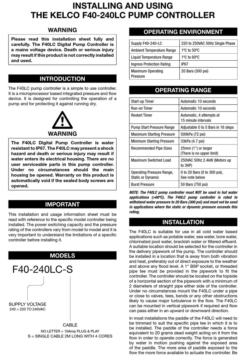
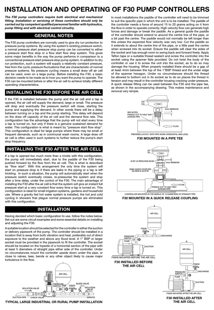
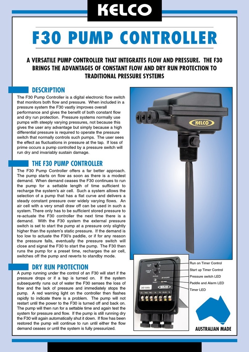
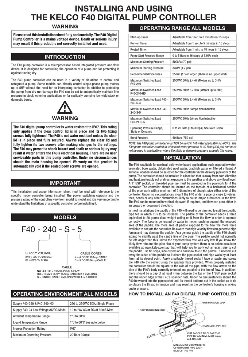
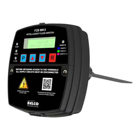
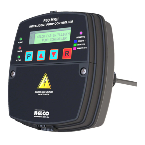
KELCO F60 Installation manual

KELCO F60
DIGITAL PUMP CONTROLLER
PROGRAMMING INSTRUCTIONS
KELCO Engineering Pty Ltd
Sydney Australia
www.kelco.com.au

Table Of Contents
Introduction 1
Programming the Controller 2
F60 Modes and Functions, Mode 1 3
Modes 2 & 3 4
Pressure System Operation 5
Pressure Settings 6
Pre Start Delay Timer 7
Running on the Snore 8
Delayed Restarting 9
Cyclic Running 10
Run Dry Auto Restart 11
Anti-Cycling 12
Burst Pipe Detector 13
LCD Screen Back Light 14
Leak Detector 15
Remote Input 15
Program Lock 16
Please Read Me First
The F60 pump controller is supplied pre-loaded with a simple program. It
is set to mode 1 and it has it’s startup and run-on timers both set to 10
seconds. All other functions are turned off or set to zero. Provided the F60
is unlocked you can restore it to this default state at any time by pressing
and holding down the (P) button and pressing the (R) reset button at the
same time. Doing this removes any settings you may have entered and
restores the controller to its original default state.

Introduction
The F60 pump controller includes a set of functions that can be set up to control
a pump. The functions range from a simple override on start timer that allows a
pump to start in spite of an initial lack of ow, through to sophisticated cyclic
running and stopping sequences. The functions are independently accessible
and adjustable through the F60’s simple programming interface. The pages that
follow set out what each function does and how to set it up.
The actual selection of a suitable mode of operation and the functions used from
a specic mode must be decided prior to programming and will depend on what
level of control the pumping system requires. In order to achieve the best
performance from this pump controller observe the following basic rules.
1) Use the least number of functions possible. Do not program in functions you
do not specically require, as to do so will make the system’s operation
unnecessarily complicated and may introduce unpredictable interactions between
the various functions.
2) When moving from mode to mode and from function to function always reset
time and pressure values back to zero before moving on. Do not leave timers
setup with some value entered in and subsequently decide not to use that specic
function. If you do this then enter zero values into the timers and pressure setting
before exiting the unrequired function. Provided the f60 is unlocked, a quick way
to reset it and clear out any unwanted settings is to press and hold down the (P)
button while also pressing the (R) reset button. Doing this clears all settings out
of the controller and loads in a very basic mode 1 program.
3) Set realistic and sensible values into the various functions. For example do
not set a pump to stop at a lower pressure than it is set to start at. Always set the
controller’s starting and stopping pressure differential to as wide a difference as
possible.
1

Programming The Controller
This pump controller is fully programmable; it accepts input via 4 push buttons.
The buttons are marked P for programming, Up and Down for data entry and a
reset button R. Pressing the P button during normal operation stops the pump and
allows entry to the controller’s menu. Subsequent pressing of the P button steps
you through the menu from one option to the next. Each option can be adjusted
using the up and down buttons.
Pressing the P button stores the settings you make into the F60’s memory and
steps you to the next option. When you reach the end of the option list the controller
asks you to press the reset button to accept the settings you have made and to
resume normal running. You can automatically save any changes you have made
and exit out of the menu at any stage during programming by simply pressing the
reset button. The settings you make are non volatile and are recorded in the
controller’s memory. Your setting will not be lost if the controller is switched off for
extended periods. When the unit is switched back on the controller will automatically
boot up and operate using the setting recorded in its memory.
The Three Operating Modes
The F60 can be set to operate in one of 3 fundamental operating modes. An initial
choice must be made as to how you want to control the pump. Once you have
made your choice, the F60’s menu will ask you a series of questions that relate to
the specic mode you have chosen. A table of the available functions is included
here to assist with selection of a suitable mode. The 3 modes are: -
Mode 1 Timer Control
In this operating mode the controller operates under time based control and
ignores the system pressure. Mode 1 provides you with a set of basic timers that
includes a start-up timer to allow the pump to initially start regardless of lack of
ow, a snore timer to allow the pump to run partially dry, a run-on timer to ignore
short term interruptions to ow. In addition delayed restarting is available as is
anti-cycling and burst pipe detection. In basic mode the controller will start the
pump each time power is switched on or each time water ow pushes the paddle
forward. The controller can also be started using an external input from a remote
switch. See the section on remote input for more information.
2

F60 Modes & Functions
MODE 1 2 3
Functions (# Settable)
# Select pressure units kPa or psi Y Y Y
# Pre-start delay timer Y Y Y
# Start-up timer Y Y Y
# Run on the snore timer Y Y Y
# Run-on timer Y Y Y
# Delayed re-starting timer Y Y Y
# Starting pressure Y Y
# Stopping pressure Y
# Cyclic running and stopping timers Y Y
# Burst pipe detection Y Y Y
# Auto restart if run dry Y Y
# Anti-cycling Y Y Y
# Leak detector Y
# Starts the pump at a preset low pressure Y Y
# Stops the pump at a preset high pressure Y
Stops the pump if ow stops. Y Y Y
Displays the system pressure in preferred units Y Y Y
Displays the high & low pressure set points Y
Can start or start & stop the pump using an external
switch (with voltage free contacts) Y Y Y
Starts & stops the pump on ow regardless of pressure Y
In Mode 1 the controller does not utilise its internal pressure sensor to control the
pump. Pump control is solely based on ow and time. The controller’s pressure
sensor is used to display the system’s dynamic pressure on its LCD screen during
normal operation.
3

Mode 2 Flow Control
In this mode the F60 will start the pump each time the pressure falls below a
preset value or whenever the controller’s paddle is pushed to the on position by
ow. It will then run the pump entirely on ow. Unlike a conventional pressure
system that operates between a low pressure cut-in and a high pressure cut-out,
in mode 2 the controller only uses the pressure set point to start the pump, not to
stop it.
Once started, the F60 runs the pump while ever ow is present, thus providing a
relatively steady constant ow. The pump is only shut down when ow stops or if
the pump runs dry. A momentary contact external switch can also be used to
trigger the starting and or the stopping of the pump in this operating mode.
Mode 3 Pressure Control
If this mode is chosen the controller will start and stop the pump under the control
of the F60’s built in pressure sensor. A high pressure cut-out point and low
pressure cut-in point are programmed into the controller’s memory and thereafter
the pump is run within these pressure limits. If the pressure rises above the high
pressure set point the pump will shut down. If the pressure falls to below the low
pressure set point, the pump will start. If the pump runs dry, this is sensed as a
combination of loss of ow and low pressure. In this situation the pump will shut
down and go into alarm mode.
In mode 3 the pump controller can also be connected to an external switch. The
pump controller will start the pump each time the external switch closes its
contacts. The contacts of the external switch can be set to only operate the pump
while they remain closed or they can be set to only trigger the starting of the pump
and not its stopping. Since the F60’s remote input operates at low voltage and
low current, a low Wattage external switch, such as a tank level switch can be
used to control a large powerful pump without the need for an interposing pump
starter or relay. See the section on page 15 detailing the use of the remote input.
4

The Options in Detail
Pressure System Operation
If operated in mode 3 the F60 will only start the pump on ow on a rising pressure.
Consider a standard pressure system operated through a pressure switch. The
pump will start each time the pressure switch closes its contacts and stop each
time the pressure switch opens its contacts. This means that in a system with a
large air cell the pump once started will run continuously until the system is fully
pressurised, regardless of demand. The F60 operates in a different way.
The pump will start at a settable low pressure. It will run while ever ow is present
and only stop when ow stops or the pressure rises to whatever you have set its
high pressure cut-out to. If there is no ow demand the pump will only run on for
whatever time you have set on the run-on timer, perhaps a few seconds and then
it will stop. It will not pump continuously until the high pressure limit is reached,
as a normal pressure system will.
If a valve subsequently opens, ow will be sensed and the pump will instantly
start. The effect of this is to give the user a relatively constant pressure. Each
time the pump starts it does so at the pressure it last stopped at, rather than only
starting from low pressure. With frequent opening and closing of valves the system
pressure may rise and eventually reach the set cut-out pressure.
The pump will then stop regardless of any ow demand. Thereafter any ow
demand will not start the pump. In other words in this operating mode the F60 will
not start a pump on ow on a falling pressure, only on a rising pressure. This is
to prevent the pump from hunting on and off around the high pressure cut-out
point. On a falling pressure demand will be met by draw off from the system’s air
cell only. Once the system’s pressure falls to whatever pressure you have set the
cut-in pressure to, the pump will start and again revert to starting and stopping on
ow demand.
On pressing the P button you are presented with a Kelco splash screen. Pressing
P again steps you to a screen that displays the F60’s model number. The screen
that follows allows you to select the pressure units you prefer, either kPa or psi.
Use the up or down keys to select between the two units. Once you have made
your choice press the P button to step to the next selection which is the pre-start
delay timer. Use the up and down keys to select Yes or No for this option.
5

If you choose yes, the screen that follows will ask you to enter the required time
delay. Use the up and down keys to set the required delay and then press P to
record the settings to memory and move to the next option. The next screen you
are presented with is the mode selection screen. Press P to step to the rst
choice which is Mode 1 Timer Control. Use the up and down keys to view the
other two modes, Mode 2 Flow Control and Mode 3 Pressure Control. Once you
have decided which mode you require, press P to accept your selection and move
to the next screen. From this point on the functions available to you will depend
on which mode you have chosen.
As you step through the available choices certain functions will be available to
you to use and certain functions will not appear. Some functions are common to
all modes and some are mode specic. The controller’s menu has sufcient
intelligence to identify selections you make and to only make available to you
functions that will work with the choices you have made. The functions that follow
are mode specic and may or may not be available to you depending on the
choices you have made up to this point.
Pressure Settings
If you select mode 2 or 3 from the mode menu, the screens that follow will ask you
to enter starting and possibly stopping pressure in whatever pressure units you
have chosen to use. Enter sensible pressures that are within the range of the
pump and include a reasonable differential between starting and stopping
pressures. If you set the starting pressure higher than the stopping pressure, the
F60 will not operate and will display a warning screen to the effect that the
pressures have to be set correctly.
If you set the pressure differential (the difference between the starting and stopping
pressure) too small the system may hunt on and off. This condition will be more
pronounced if the system has no air cell or the capacity of the pipework is small.
The F60’s ability to operate on a close differential can be a major advantage in
certain circumstances.
In theory the cut-out pressure of the F60 can be set to 1kPa higher than the cut-in
pressure. With such a setting the controller will operate on a differential of 1kPa.
For actual practical usage, background pressure uctuations and temperature
variation in the system will reduce the actual usable minimum pressure differential
to perhaps 10 or more kPa which is still considerably less than that of a conventional
pressure switch.
6

Pre-Start Delay Timer
The pre-start delay timer delays the starting of the pump for a selectable period.
It can be set from zero to 240 seconds (4 minutes) in one second increments. If
you choose to use this timer the actual starting of the pump will be delayed by
whatever delay you set this timer to. Each time the controller is switched on it
boots up and is prevented from starting the pump for the set time period. As soon
as the set time has elapsed the pump will start and run normally, given there is a
demand for water. The pre-start timer can be used to allow peripheral equipment
time to boot up. For example, some VS drives require a few seconds to stabilise
and the F60’s pre-run timer can hold off the starting of the pump until the whole
system has stabilised. The pre-start timer can also be used to stage or stagger
the starting of multiple pumps. It is often desirable to avoid the high current draw
of multiple motors starting together, and the pre-start timer can facilitate this
function.
Start Up Timer
The F60 uses a paddle to detect ow. The paddle is held in the no-ow position
by an adjustable magnetic screw that is located in a port under the electrical
housing of the controller. If ow pushes against the paddle, the paddle moves.
The movement is detected by the controller and identied as ow. Initially in a
system that is not running or has all its valves shut, there will be no ow and the
controller’s paddle will be in the off or no ow position. In order to override this
initial off state and allow the pump to start, the controller uses the start-up timer.
The timer ignores the initial off state of the paddle and allows the pump to run for
a settable time. As soon as ow is detected the start timer terminates its run and
hands control of the pump over to the paddle. The startup timer in the F60 is
adjustable from 0 to 240 seconds (0 to 4 minutes) in 1-second increments. The
value you enter will depend entirely on your pump system. For a fully primed
pressure system or transfer pump, the start-up timer may only require one or two
seconds to establish ow. In a submersible bore pump installation with a self-
draining riser, it may take several minutes to establish ow past the paddle. If the
start-up timer is set to zero the pump controller behaves as a simple ON/OFF ow
switch, responding solely to the state of its paddle.
In normal operation the F60 will display the system’s dynamic pressure in whatever
pressure units you have chosen whenever it is running normally or is waiting to
start. It will also display any pressure set points you have entered. For example,
when operating in mode 3 the LCD screen will display the current system pressure
and the high and low pressure set points. From the display it is then a simple
matter to watch the system pressure rise or fall toward the preset trip points that
you have set the system to operate within.
7

Run-on Timer
Running On The Snore
The snore timer allows the controller to ignore continuous paddle bounce due to
entrained air or gas in piping systems. In situations where entrained gas or air in
the pipework is an ongoing problem and is constantly present in a pipe system,
the snore timer allows the controller to ignore the gas bubbles and keep the pump
running stably. When entrained gas moves past the paddle of the F60 the paddle
bounces back and forward. The snore timer monitors the movement of the paddle
and each time the paddle bounces, the snore timer resets itself and commences
its timed run again.
The automatic resetting action ensures the pump controller does not identify the
minor interruptions to ow as a dry run situation. The snore time can be set to any
value from 0 to 240 seconds (0 to 4 minutes) in increments of 1 second. The F60
identies a dry run situation when the paddle has remained in the off position for
longer than the time you have set on the snore timer. If the off time exceeds the
snore timer’s setting the F60 shuts down the pump and goes into alarm mode.
Care should be taken when using the snore timer to ensure the pump being used
is suitable for being run when partially dry. Please contact your pump supplier
before using the snore timer to ensure your pump is suitable for such operation.
For most applications the snore timer should be initially set to a few seconds only.
In normal operation, in systems where entrained gas is not an issue, the F60
digital pump controller’s built in run-on timer can be set to ignore minor interruptions
to ow. For example, if air trapped in the pipework passes the controller’s paddle,
the paddle will momentarily swing into the no ow position. This would normally
cause the controller to shut down the pump. The run-on timer lets the controller
ignore such minor uctuations in ow. Once triggered, the run-on timer simply
runs for whatever time you have set it to. During this run period it ignores the state
of the paddle and simply runs the pump. At the end of its set run time, it looks at
the state of the paddle and if ow is present, resumes normal operation. If ow is
not present at the end of the run-on time, the controller shuts down the pump and
goes into alarm mode because it considers the pump to be running dry. It is
important to note that unlike the snore timer, the state of the paddle is not monitored
continuously while the run-on timer is running. The paddle can bounce back and
forward and the run-on timer will ignore it.
8

It is only the state of the paddle at the end of the run-on time that determines
whether the pump returns to normal operation or goes into alarm mode. The run-
on timer can be set to any value from 0 to 900 seconds (0 to 15 minutes) in
increments of 1 second. For most applications an initial setting of a few seconds
is quite adequate.
Delayed Restarting
If you set this option to ON, each time the pump stops, due to ow stopping or
pressure rising above your set point, the F60 controller will prevent the pump from
restarting for the set period of time. The delay time can be set from zero to 99
hours 59 minutes (zero to just over 4 days) in steps of 1 minute. Delayed starting
is a form of anti-cycling and cyclic running, wherein the pump is limited in its ability
to cycle on and off by being prevented from restarting for a set time period. Its
uses include preventing rapid cycling if the system’s air cell becomes water logged
or if a fault develops in a system’s external controls. As an example of its use,
consider a pressure system lling a remote tank. If the tank has a oat valve that
shuts when the tank is full, then the system will pressurise and shut down each
time the tank lls and the valve closes. If the oat valve leaks or the level drops
and the valve opens the system will depressurise and the pump would ordinarily
start. By utilizing the F60’s delayed starting feature, the restarting of the pump can
be delayed for a period of time. Perhaps until the water level in the tank has
dropped by a substantial amount.
If you choose to use the delayed starting function and press P, you will be asked
to enter the delay in hours and minutes. You will then be asked if you want
automatic starting at the end of the delay period. If you choose yes to this question
the controller will automatically start your pump at the end of the delay period. If
you choose no, the controller will only start the pump after the delay if the pressure
is lower than your set pressure, or if the external switch closes or ow is present.
In the example outlined above, consider a tank that has intermittent or irregular
draw off. You may choose to set the delayed restart to perhaps 12 hours. At the
end of the 12 hour period the pump will automatically start and if the tank level is
low, the pump will run continuously until the tank lls and the oat valve in the tank
closes. If however, there has been no draw off from the tank during the 12 hour
period, the automatic restart at the end of the delay will start the pump and run it
for whatever period you have set on the start timer (perhaps a few seconds). The
F60 will sense no ow because the oat valve will still be closed. The F60 will then
shut down the pump and again wait for 12 hours before again attempting to start
the pump.
9

Cyclic Running
Using this technique prevents the pump from hunting on and off when the tank is
full because of slight leakage from the oat valve or pipework. It allows you to set
the pump to only operate after a chosen delay, and if there has been no usage of
water, to test the system for demand by momentarily starting and only running the
pump if there is a genuine call for water.
The delayed starting function is distinctly different in the way it operates to the
cyclic running function that is also included in the F60. Delayed starting has no
xed run time. The pump will run continuously provided ow is present until it is
stopped by a valve closing or until it runs dry. Cyclic running allows you to set how
long the pump runs for as well as how long it stops for. If you choose to use the
delayed starting option the cyclic running function that follows it will not be
available to you, as its operation offers an alternative to cyclic running that
excludes the combination of the two functions.
The cyclic running option is only available in modes 1 and 2. It is not available if
you have chosen mode 3. The F60 can be programmed to run and stop a pump
for set periods of time. Both the running and stopping times can be set to any
value you choose from 1 minute to 99 hours 59 minutes (zero to just over 4 days)
in increments of 1 minute. The cyclic running option is highly exible. The run
and stop timers are totally independent of each other. If a set running and stopping
time are programmed in, the F60 will run the pump for whatever time it is set to
and then stop for the time set on its stop timer. If a run time is set to some value
and the stop time is left set at zero, the pump controller will behave as a one-shot
batch controller. On pressing the reset button or switching the pump on, the
pump will run for the set period and then shut down. It will not then restart until
you again press the reset button or reset the power to the unit. In cyclic running
mode the F60 monitors the elapsed time and displays the remaining time on its
LCD screen in hours and minutes.
Cyclic running allows low yield bores to be pumped to their maximum capacity. A
bore pump running under cyclic control can be set to pump the bore down to a low
level, stop and wait for the standing water level to recover and then repeat the
process endlessly all the while protecting it if it runs dry. For transfer pumping
applications cyclic running can be used to automatically top up remote tanks
without the need for oat valves or level control at the tank. It can also be used for
one-shot tank lling. Press the reset button and pump a set number of hours or
minutes of water to a tank, and then stop until the reset button is again pressed.
10

If the pump runs dry and the controller is set to mode 2 or 3 it will identify a dry run
situation as a loss of both pressure and ow. The F60 is not capable of identifying
a dry run condition in mode 1 because in mode 1 it only monitors ow and not the
system’s pressure. To identify dry run, the controller must monitor both ow and
pressure, which it only does in modes 2 and 3.
If the F60 is set to operate in mode 2 or 3 it will identify any dry run situation that
may occur and respond by shutting the pump down, thus preventing damage to
the pump. In such a situation the controller displays a “pump ran dry” message
and rapidly ashes all its lights to indicate there is a problem and closes the
contacts of its alarm relay. The alarm relay can be used to control a remote alarm
light, a siren or any other required device such as a telemetry system.
Alternatively, the F60 can be set to automatically attempt to restart and recover
from a dry run situation after a set period of time. This process is called auto
restart. If this option is chosen the controller’s menu presents you with a choice,
single restart or repeated restarts. Single restart will attempt to restart the pump
after a set time and if the attempt fails the F60 then shuts down the pump and
goes into permanent alarm mode. It displays a “pump ran dry” message, ashes
all its lights and closes the contacts of its alarm relay. If however, it nds ow and
or pressure when it restarts it resumes normal operation. If you choose repeated
restart from the menu the controller will repeat the shut down and wait sequence
and it will not go into permanent alarm mode. Once you choose repeated restart
or single restart the screens that follow ask you to enter a waiting period in hours
and minutes. The range of adjustment is 1 minute to 99 hours 59 minutes (zero
to just over 4 days) in one minute increments. If the pump runs dry the F60 will
shut it down and wait for the period you have set before attempting to restart.
The ability to restart the pump automatically if it runs dry can be a very useful
function. Consider a self priming jet pump or submersible pump installed in a low
yield bore. The bore can be pumped until dry and the pump under the control of
the F60 can be set to shut down as soon as loss of ow is detected and then wait
until the standing water level in the bore recovers before attempting to restart and
again pump the bore down. Such a system maximises the yield from the bore
and automatically compensates for seasonal uctuations in the bores capacity.
Run Dry Auto Restart
11

Anti-Cycling
Electric motors are often limited in the number of times they can be safely started
in an hour. This is particularly important in the operation of submersible bore
pumps. When a motor starts there is an initial inrush of current that produces
heat in the coils and iron rotor of the motor. If the frequency of starts is excessive
the accumulation of heat within the motor can cause severe damage and eventual
failure of the motor. Submersible bore pump motors are particularly prone to
damage from excessive cycling (starting and stopping).
The anti-cycling option built into the F60 allows the user to set the maximum
number of times the pump can be safely started in any one hour period. If you
select yes to this option the screen that follows will ask you to enter the maximum
number of times the pump can be started in any one hour. The number of starts
can be set from 1 start per hour to 1800 starts per hour. Please contact your
pump supplier to obtain the correct gure for your specic pump. In operation the
anti-cycling system monitors both time and the number of starts and compares
the two. If the starts per hour rate is exceeded 5 consecutive times in any one
hour period the pump will be automatically shut down and the controller will display
a message indicating the starts per hour rate was exceeded.
As a simple example of the way the anti-cycling system works, if the starts per
hour rate is set to 360 (one start every 10 seconds maximum) and the pump starts
4 times in a row at less than 10 seconds between each start and then does not
start again for 12 seconds the anti-cycling shutdown will not be invoked. If
however, the pump were to start 5 times in a row with less than 10 seconds
between the starts the anti-cycling system would be invoked and the pump would
be shut down.
In a conventional pressure system the anti-cycling function can be used to protect
the pump from damage in the event of the system’s air cell losing its air charge.
If air is lost from a system’s air cell due to a ruptured diaphragm or leaking air
valve, the pump will hunt on and off rapidly. Such rapid cycling will cause the
pump to overheat very quickly. The F60’s anti cycling feature can be used to shut
down the pump and prevent damage in such a situation. To use the anti-cycling
function for this type of pump protection simply set the starts per hour to some
value that is marginally higher than the system’s normal start rate. This will avoid
nuisance tripping but will shut the pump down if excessive sequential cycling is
encountered.
12

The F60 includes a unique system for detecting burst pipes. The burst pipe
detection system can be used in all modes. It is most commonly used in pressure
systems.
If a pressure system bursts its discharge pipe the system pressure will fall and the
pump will start at its low pressure setting. The pump will then run continuously
until the water source is depleted. If the discharge pipe splits and the pump has
sufcient capacity the result may be continuous cycling of the pump as it attempts
to satisfy the leak. The F60 addresses these two scenarios with two separate
functions, anti-cycling and burst pipe detection. When both functions are activated
the complete spectrum of burst pipe scenarios are covered. Anti cycling will
detect cyclic starting and stopping and can be set to shut the pump down after a
predetermined number of cycles. This function detects split and leaking pipes.
The burst pipe detector addresses the issue of a completely burst pipe where the
pump would ordinarily discharge at its full capacity until the source of water was
depleted. It does this by using a timer that times out for a settable period each
time the pump runs. The timer resets back to its original setting each time the
pump stops. The range of adjustment is zero to 99 hours 59 minutes in steps of
1 minute.
In a typical application the burst pipe detector would be set to a time that was
marginally longer than the longest time the pump would ordinarily run. For
example, in a domestic pressure system day to day usage may require the pump
to run for no longer than 15 minutes (for showers etc.). Perhaps once every few
days the system is used for garden watering and required to run for 30 minutes.
In this scenario the burst pipe detector would be set to perhaps 40 minutes.
Each time the pump switches on the burst pipe detector begins to count down. In
normal circumstances the pump will shut off in less than 30 minutes. This resets
the burst pipe detector’s timer back to 40 minutes. If however, the pump continues
to run, due perhaps to a burst pipe, it will eventually reach the set point of 40
minutes.
Burst Pipe Detector
13

The pump will then be instantly shut down preserving whatever source water
remains, or at least reducing the discharge ow by an amount equal to the pump’s
capacity. The F60 will then display “burst pipe detected” on its LCD screen.
The setting of the burst pipe detector is a matter of balance between nuisance
tripping and maximum preservation of the water source. If the burst pipe detection
timer is set too close to the actual maximum usage time, the system may trip out
occasionally due to slightly excessive water usage. If however, the timer is set
too long the result will be wasted water in the event of a genuine burst pipe.
The burst pipe detection system can be used to protect water reserves in tank
lling and transfer pump applications. As an example, consider a tank lling
application. The capacity of the pump and the tank are known so the maximum
run time of such a system will be the time required to ll the tank when it is
completely empty. Draw off from the tank may add to this time but fundamentally
the time will be known within reasonable bounds. If the level switch in the tank
fails or the oat valve fails and the tank continuously overows, eventually the
pump under the control of the F60’s burst pipe detector will reach the burst pipe
detector’s set point. The pump will then be shut down preserving what remains
of the water source.
14
LCD Screen Back Light
The LCD screen on the F60 pump controller has a built in backlight. The backlight
switches on automatically whenever you are programming the controller and
when the controller is displaying certain fault conditions. In normal operation the
backlight remains off.
The LCD screen backlight can be switched on manually at any time by pressing
and holding down the down arrow button. The screen will remain illuminated
while ever you are depressing the down button. The screen will switch off as soon
as you release the button. The LCD backlight can’t be permanently switched on,
it only operates while the down button is held in.

Leak Detector
The F60 includes a unique leak detection system that can be used as a tool to
analyse suspected leakage in a pressurised pumping system. The leak detector
only operates in mode 3. It can be switched on or off in the main menu. It should
be left switched off when not required as its display screen excludes the display
of normal system pressure and messages when it is in use. To use the leak
detector, open all valves feeding into the pipe system to be tested. Close all
valves at the far ends of the pipework so the pipe system can be pressurised.
Press the reset button on the controller, this will zero the leak detector screen and
run the pump until the system is fully pressurised. Leave the system unattended
for a period of time perhaps an hour or even a day or two. On returning to the
system, the controller’s LCD screen will be displaying the number of times the
pump started and the total run time in hours minutes and seconds since the time
the leak detector was zeroed. If the leak detector screen displays no starts and
no run time, then no leak has occurred from the system in the interim period. If the
screen displays a number of starts and a total run time, a leak has occurred and
the magnitude of the leak can be assessed by considering the total run time
displayed and the capacity of the specic pump. The leak detector can be used
in any pressurised pumping system from a small domestic pressure or transfer
system to complex irrigation and stock watering systems comprised of many
kilometres of pipe.
15
Remote Input
The F60 provides the user with a non-isolated nominal 24VAC supply from its LV
(Low Voltage) active terminal whenever the F60 is operated from the mains or
from a 24VAC supply. The 24VAC supply can be connected through a remote
switch and the return wire can be connected to the “R” (remote input) terminal on
the F60’s terminal block. When operated from a 24VAC or DC supply, the 24V
active or the supply positive can be used as the source of low voltage to the
remote switch and the return wire can be connected to the “R” terminal. It is
critical that the remote switch has voltage free contacts. Under no circumstances
apply an external voltage directly to the “R” terminal of the F60 pump controller.
See the F60 Installation Manual for further details.
An external switch such as a tank level switch or a set of external voltage free
relay contacts can be used to actuate the F60 controller. The external or remote
switch will operate the F60 in all 3 operating modes.

The F60 includes a hidden lock. When activated the lock disables the programming
button P, thus rendering the controller’s menu inaccessible.
To lock or unlock the F60, press the up and down buttons together while the pump
is in normal operation (not while it is being programmed). Pressing the up and
down buttons together while in normal running mode shuts the pump down and
opens the controller’s lock screen.
Once the lock screen is displayed the F60 can be locked or unlocked by pressing
the up or down buttons. Pressing P then exits the lock screen and the controller
resumes normal operation. When locked, pressing the (P) button has no effect on
the F60 and does not take you into the menu in the usual way. Access to the menu
can then only be obtained by rst unlocking the (P) key.
Program Lock
The controllers menu asks you if you intend using a remote input. If you select
yes you are then asked if you require the external switch to simply trigger the
starting of the pump only or if you want the external switch to also control the
stopping of the pump. If you choose “starting only” the pump will start each time
the external switch closes its contacts. Once the pump has started the external
switch can open its contacts or they can remain closed without any effect on the
operation of the pump. The F60 ignores the state of the external switch once the
pump has started.
If you choose to have the F60 both start and stop the pump then the contacts of
the external switch must remain closed while ever the pump is required to run. If
the contacts of the remote switch open, the F60 will immediately shut the pump
down and display a message “remote switch is off”. The F60 will then not allow
the pump to restart until the remote switch closes its contacts.
Following is an example of the use of the remote input. If the pump were to be
controlled by an external tank level switch that started the pump each time the
tank emptied and stopped the pump each time the tank lled then you would
choose to use the external remote input in “start and stop the pump” mode. If you
required the pump to start each time an external relay or switch closed its contacts
and thereafter run under the control of the F60 then you would choose “start the
pump only” from the F60’s menu.
16

If the F60 Pump Controller is used in a
manner not specied by the manufacturer
the pump protection provided by the
controller may be impaired or negated. In
addition, all warranties stated or implied will
be rendered invalid.
WARNING
Designed and Manufactured in Australia by
KELCO Engineering Pty Ltd
A.B.N. 20 002 834 844
Head Ofce and Factory: 9/9 Powells Road Brookvale 2100 Australia
Postal Address: PO Box 496 BROOKVALE NSW 2100
Web: www.kelco.com.au
PLEASE NOTE: Kelco Engineering Pty Ltd reserves the right to change the specication of this
product without notice. Kelco Engineering Pty Ltd accepts no liability for personal injury or
economic loss as a consequence of the use of this product. All rights reserved copyright Kelco
Engineering Pty Ltd © 2013

Version 3. Date: 10/04/2013 KF
Other manuals for F60
1
Table of contents
Other KELCO Controllers manuals
Popular Controllers manuals by other brands

Woodward
Woodward easYgen-1600 Operation manual

Sinclair
Sinclair KJR- 90D Installation and user manual

National Instruments
National Instruments PXI-7356 Getting started

Leslie
Leslie 35 Installation, operating and maintenance instructions

Sonos
Sonos CONNECT:AMP Product guide

Crestron
Crestron HD-CTL-101 product manual