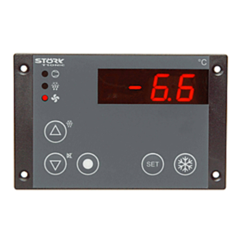
STORK TRONIC ST501-JX1TA User manual

ST501-JX1TA
Temperature controller for fan drawers
Order number 900219.024
Old Id.Nr.: 149674
Wiring diagram
Product description
The ST501-JX1TA controller comprises a control unit and a power supply unit board. Both com-
ponents are interconnected via a ribbon cable and form a plug-in unit. All input and output connec-
tions are established in the rear on the power supply unit board. The unit provides the functionality
of a temperature controller for fan drawers.
A triac for fan control and a relay are provided as outputs. The relay is a normally open contact and
canbedefinedeitherascontrolcircuit2orasanalarmcontactusingtheparametersettingfunction.
Sensor: PTC, Pt100
Range: dependent on type of sensor
Front dimensions: 106mm x 68mm
Panel cutout: 87.5mm x 56.5mm
Tightness: Front IP65
Connection: screw terminals
Versorgung: 230V AC
1

2

SOFTWARE for fan control
Adjustment options
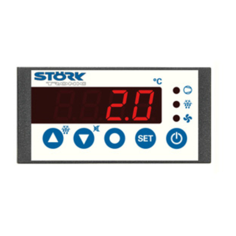
UP key
Press this key to increment the parameter number or parameter value.
DOWN key
Press this key to decrement the parameter number or parameter value. In the event of
an alarm, the buzzer is silenced by pressing this key.
SET key
The setpoint is displayed while this key is pressed.
This key is also used to set parameter values.
Standby key
This key switches the controller to the standby mode. Press the key again to switch the
controller back on.
First control level:
Parametrization of primary setpoint
The actual value is always shown on the setpoint display.
Press the SET key to display the setpoint setting. Additionally press the UP key or DOWN key to
adjust the value.
Para-
meter Function description Adjustment range Default
setting Custom
setting
S1 Primary setpoint P4 ... P5 20.0 °C

Second control level (P parameters):
Setting of control parameters
Press and hold the UP and DOWN keys simultaneously for at least 4 seconds to access a
parameter list containing control parameters. Press the UP key to scroll up in the list and the
DOWN key to scroll downin the list.
Press the SET key to display the value of the parameter in question. Additionally press the UP key
or DOWN key to adjust the value.
Once you release all keys, the new value is permanently stored. If no key is pressed for more than
60 seconds,the unit automatically returns to its initial state.
Para-
meter Function description Adjustment range Default
setting Custom
setting
P0 Displays the actual value from
sensor F1 ----- -----
P1 Setpoint 2 / delta W
Control circuit 2 P4 ... P5
-99 ... 99 K
Delta W: -10 K
P2 Hysteresis, control circuit 1 0.1 ... 99.9 K 1.0 K
P3 Hysteresis, control circuit 2 0.1 ... 99.9 K 1.0 K
P4 Lower control range limit -99 °C ... P5 -99 °C
P5 Upper control range limit P4 ... 999 °C 999 °C
P6 Actual value correction -20 ... +20 K 0.0 K
P7 Proportional band 0.1 ... 100 K 10.0 K
P8 Reset time Tn 0 ... 999 seconds
(0 = inactive) 0 sec.
P9 Derivative time Tv 0 ... 999 seconds
(0 = inactive) 0 sec.
P10 Cycle time 1 ...100 sec. 1 sec.
P19 Keypad locking 0: not locked
1: locked 0
P30 Lower alarm limit -99 °C/K ... P31 -99 K
P31 Upper alarm limit P30 ... 999 °C/K 999 K
P32 Hysteresis, alarm contact 0.1 ... 99 K 1.0 K
P33 Lower limit for fan 5 ...100 % PWM 50 %
P34 Upper limit for fan 5 ...100 % PWM 95 %
P35 Start-up boost time 0...60 seconds
(0 = inactive) 1 sec.

Parameter description:
P1: Setpoint 2 / delta W
The second setpoint affects control circuit 2 and can be adjusted in 2 variants (see parameter A5
for selection):
First controller variant (cf. figure 1):
Contacts K1 and K2 are linked via switching
difference delta W (operation with delta W).
This difference may take on positive or
negative values. This allows you to
implement a leading or following secondary
contact.
Setpoint S1
(contact K1)
DeltaW
Setpoint S2
(contact K2)
t
T
Figure 1
Second controller variant (cf. figure 2):
Contacts K1 and K2 can be adjusted
independently. (Operation with setpoint 2.)
Contact K1 is based on setpoint 1, and K2 is
based on setpoint 2, which can be assigned a
limit function.
Setpoint S1
(contact K1)
Setpoint S2
(contact K2)
t
T
Figure 2
Note: When a PID control is implemented for contacts K1 + K2, setpoint 1 affects both contacts.
P2/P3: Hysteresis, K1/K2
The hysteresis may be symmetrical or one-sided relative to the setpoint (see A40, A41). When the
one-sided setting is chosen, the hysteresis works downward with the heating contact and upward
with the cooling contact. When the symmetrical hysteresis function is chosen, half of the hysteresis
value is effective above and half of the value below the switching point (cf. figures 3 and 4).
Figure 3: Heating controller, one-sided hysteresis Figure 4: Cooling controller, symm. hysteresis
P4/P5: Upper/lower control range limit
The adjustment range of the setpoint can be limited in both directions. The purpose of this is to
prevent the operator of a unit from setting impermissible or dangerous setpoints.
P6: Actual value correction
A correction can be applied to the actual value. This correction value is added to the actual value
across the entire measuring range.
P7: Proportional band
In the proportional band, the output is controlled in proportion to the deviation from the setpoint.
The greater the system deviation, the greater the control output.

P8: Reset time Tn, I-portion
The proportional controller as such has a remaining deviation of the actual value from the setpoint.
The integral portion provides for a complete compensation of this offset.
The reset time is a measure for the period of time needed to adjust a remaining temperature
deviation of the size of the proportional range.
If a small reset time is set, a fast post-adjustment will take place. At a too small reset time,
however, the system may tend to vibrate
P9: Derivative time Tv, D-portion
The differential portion dampens temperature changes. If a long derivative time Tv is set, damping
is strong. At too long derivativetime, however, the system may tend to vibrate. At setting 0 the
values are ineffective. It is therefore possible to realizea pure PI or PD regulation.
P10: Cycle time Tp
The cycle time is the time during which the control output cycles through a switching period, that is
from On through Off. The lower the cycle time setting, the faster the control. However, this also
results in increased output switching frequency, which may quickly wear out relay contacts.
In the case of veryfast processes with high switching frequencies, a voltage output is therefore
preferable.
P19: Keypad locking
The keypad locking function can be used to block the control keys. When keypad locking is
enabled, the setpoint cannot be changed. Any attempt to change parameters with keypad locking
enabled will display the message “===”.
P30: Lower alarm limit
P31: Upper alarm limit
A limit or range alarm with a fixed hysteresis of 1.0 K is signaled using lamp 3 or contact K3.
Function as a limit alarm (cf. figure 5):
If the actual value is outside the defined
temperature limits (that is, above the upper
limit or below the lower limit), the alarm
contact is active.
Figure 5
Function as a range alarm (cf. figure 6):
Inverted switching behavior compared to limit
alarm. Lamp 3 is lit or contact K3 is picked up
when the actual value lies within the defined
limits.
Figure 6
The limit values for the limit or the range alarm can be set to be relative, i.e. to float with the
setpoint, or to be absolute, i.e. to be independently adjustable. If only one switching point is desired
for the limit alarm, the second switching point (the one not needed) is set to a value above or below
the controller working range. It is then preferable to choose the operating mode with absolute
limits. Also see A30 within this context.

P32: Hysteresis, alarm contact
The hysteresis is to one side of the limit. In the case of the limit alarm, the hysteresis works upward
from the lower limit and downward from the upper limit. In the case of the range alarm, the
hystereses work in the opposite directions, i.e. downward from the lower limit and upward from the
upper limit.
P33: Lower limit for fan
P34: Upper limit for fan
P35: Start-up boost time
Third control level (A parameters):
Setting of control parameters
The third control level is reached by first accessing the second control level and then scrolling
through the parameter list all the way to the highest parameter (P45). Then press the UP key for a
minimum of 10 seconds. The message “PA“ appears on the display.
Press the UP and DOWN keys at the same time for a minimum of 4 seconds to access the
parameter list of the third control level (which starts with A1).
Press the UP key to scroll up in the list and the DOWN key to scroll down in the list.
Press the SET key to display the value of the parameter in question. To adjust the value,
additionally press the UP key or DOWN key.
Once you release all keys, the new value is permanently stored. If no key is pressed for more than
60 seconds, the unit automatically returns to its initial state.
Param-
eter Function description Adjustment range Default
setting Custom
setting
A1 Fan controller mode 0: heating contact
1: cooling contact
1
A2 Control circuit 2 mode
0: heating contact
1: cooling contact
1
A3 Fan controller function in the
event of a sensor error 0: relay off
1: relay on 0
A4 Control circuit 2 function in
the event of a sensor error 0: relay off
1: relay on 0
A5 Selection: setpoint 2 / delta W
control circuit 20: operation with setpoint 2
1: operation with delta W
1
A8 Display mode 0: integers
1: 0.5 K resolution
2: 0.1K resolution
2
A19 Parameter lock 0: no lock
1: A parameters locked
2: A and P parameters
locked
0

Param-
eter Function description Adjustment range Default
setting Custom
setting
A30 Alarm contact function 0: limit alarm, relative
1: limit alarm, absolute
2: range alarm, relative
3: range alarm, absolute
4: limit alarm, relative
inverted alarm contact
5: limit alarm, absolute
inverted alarm contact
6: range alarm, relative
inverted alarm contact
7: range alarm, absolute
inverted alarm contact
1
A31 Special functions for alarm 0: no special function
1: flashing display
1
A32 Default display setting 0: actual value display
1: setpoint display 0
A40 Hysteresis mode of fan
controller 0: symm. around setpoint
1: on one side of setpoint 0
A41 Hysteresis mode of control
circuit 2 0: symm. around setpoint
1: on one side of setpoint 0
A52 Minimum action time
control circuit 2 “on“ 0 … 600 sec. 0 sec.
A53 Minimum action time
control circuit 2 “off“ 0 … 600 sec. 0 sec.
A54 Delay after “power on“ 0 … 600 sec. 20 sec.
A56 Alarm suppression of limit
alarm after “power on“ 0 … 60 min. 0 min.
A57 Continuous fan operation
(outside proportional band
with value from P33)
0: no continuous operation
1: continuous operation
1
A60 Sensor selection 11: Pt100 two-wire
21: PTC
22: Pt1000 two-wire
21
A70 Software filter 1: not active, otherwise
2 ... 32: mean value of 2...32
meas. values (approx.
0.6...9.6 s)
4
A 80 Temperature scale and
display 0: Fahrenheit (AUS)
1: Celsius (AUS)
2: Fahrenheit (OFF)
3: Celsius (OFF)
1
A90 K1 output linking 0: no linking
1: linked with
control circuit 2
2: linked with
alarm contact
1
Pro Program version display ----- ----- -----

Parameter description:
The following values may change the equipment
characteristics and are therefore to be set with the utmost care:
A1: Fan controller mode
A2: Control circuit 2 mode
The controller mode (cooling or heating function) can be individually programmed for the two
control circuits at the factory. Heating function means that the contact drops out when the defined
setpoint is reached, i.e. the power supply is interrupted. In the case of the cooling function, the
contact only picks up when the actual value is above the defined setpoint.
A3: Fan controller function in the event of a sensor error
A4: Control circuit 2 function in the event of a sensor error
When the sensor is broken, the flashing display indicates F1H. When the sensor is short-circuited,
the display indicates F1L (also flashing). Parameter A3 is used to determine the output behavior
when this happens
A5: Selection of setpoint 2 / delta W for control circuit 2
This parameter determines whether the controller works with two linked contacts (operation with
delta W) or with two independently adjustable contacts (operation with setpoint 2). See P1.
A8: Display mode
This parameter selects the resolution used to display the actual value.
A19: Parameter lock
This parameter can be used to lock (block accessto) the parameter levels. When the A level is
locked, only parameter A19 can still be changed.
When the parameter lock is active, the parameters are displayed but cannot be changed via the
keys. Any attempt to change parameters with keypad locking enabled will display the message
“---“.
A30: Alarm contact function
This parameter is used to determine alarm contact behavior when the values set with parameters
P30 and P31 are reached.
Limit alarm means that an alarm is signaled when the defined limits are exceeded.
Range alarm means that an alarm is signaled within the defined limits.
Relative means that the values entered for parameters P30 and P31 represent a difference from
the setpoint. Absolute means that the values entered for parameters P30 and P31 are independent
of the setpoint.
A31: Special limit alarm function
This parameter can be used to activate additional actions for the limit alarm function.
A32: Default display setting
When parameter A32 is set to 1, the display always indicates the setpoint. It is then not possible to
display the actual value.
A40 Hysteresis mode of fan controller
A41 Hysteresis mode of control circuit 2
These parameters determine whether the hysteresis values adjusted with P2 or P3 for the fan
controller or control circuit 2 are symmetrical or one-sided relative to the switching point in
question. When the symmetrical hysteresis function is chosen, half of the hysteresis value is
effective above and half of the value below the switching point. When the one-sided setting is
chosen, the hysteresis works downward with the heating contact and upward with the cooling
contact.
A52: Minimum action time for control circuit 2 “On”
A53: Minimum action time for control circuit 2 “Off”
These parameters can be used to delay activation/deactivation of the output contact in order to
reduce the frequency of switching operations. The minimum action time defines the entire
minimum duration of a switch-on or switch-off phase. This time is also effective for the
configuration as an alarm contact.
A54: Control circuit delay after “power on”
This parameter can be used to delay the activation of the control circuit after power on. The
purpose of this is to prevent mains supply overload due to many consumers being switched on
simultaneously.
A56: Suppression of limit alarm after “power on”
When the controller is switched on, it takes a certain period of time –particularly with cooling
systems –until the operating temperature is reached. This would normally result in undesirable
alarm signaling.
Therefore parameter A56 can be used to define a period of time during which an alarm condition is
not signaled.
A57: Continuous fan operation
A60: Sensor selection
Selection of sensor. Depending on the hardware used, not all sensor types can be selected.
A70: Software filter
Calculates the mean value over the number of measurements set here.
A 80: Temperature scale
This parameter is used to switch the display between the Fahrenheit and Celsius temperature
scales. It is not available on units with a voltage or current input.
A90: K1 output linking
Status messages
Message Cause
Remedy
F1 Sensor error, resistance too high -
sensor break Check sensor
F8 Limit alarm
(if activated; triggered by temperature
monitoring of sensor F1)
Check sensor
_ _ _ Keypad locking active
see parameter P19 or A19
Flashing display
Temperature alarm (see A31)
EP Data loss in parameter memory
(control circuits 1 and 2 are de-
energized)
If the problem cannot be eliminated by
switching the controller off and back
on, the unit must be repaired

Order number: 149674
Technical dataof ST501-JX1TA
Input
F1: resistance thermometer
Range: PTC (KTY81-121) -50 °C ... +130 °C
PT1000 -99 °C ... +300 °C
Pt100 -80 °C ... +400 °C
Accuracy: ±0.5K ± 0.5 % at 25 °C, without sensor
±1K ± 0.5 % across entire temperature range (0 –+55 °C), without sensor
Outputs
K1: relay, 16(2.2)A 250V NO contact
(limited to 10(2.2)A through terminals or printed circuit board)
S1 triac output for fan
Additional buzzer, 85 dB
Display and indicators
One 3-digit LED display for temperature indication
Three LEDs for status indication
Power supply
230 V, 50/60 Hz
Connectors
12-pin screw terminal, 5.0 mm pitch, for cable cross sections of up to 2.5 mm²
Weight
Approx. 250 g, without sensor.
Type of protection
Front IP65
Ambient conditions
Storage temperature:-20 °C ... +70 °C
Operating temperature:0 ... 55 °C
Relative humidity: max. 75%, non-condensing
Installation data
Front dimensions: 106 x 68 mm
Panel cutout: 87.5 x 56.5 mm
Installation depth: approx. 50 mm
This manual suits for next models
2
Other STORK TRONIC Controllers manuals

STORK TRONIC
STORK TRONIC ST189-XRTUR.209 User manual

STORK TRONIC
STORK TRONIC ST552 Glass User manual

STORK TRONIC
STORK TRONIC ST501 Series Quick start guide

STORK TRONIC
STORK TRONIC ST96 Series Quick start guide

STORK TRONIC
STORK TRONIC ST501-KU3KA.12P User manual

STORK TRONIC
STORK TRONIC ST501-QE1TA.09 User manual

STORK TRONIC
STORK TRONIC ST710-KPLVR.112S Quick start guide

STORK TRONIC
STORK TRONIC ST121-KD1KAR.112 User manual

STORK TRONIC
STORK TRONIC ST710-PWHVR.126 Quick start guide

STORK TRONIC
STORK TRONIC ST181-LM4KAR.112 User manual