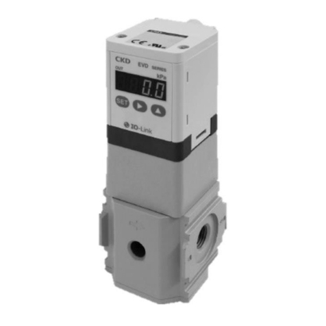
CKD EVD Series User manual

1
Digital electro pneumatic regulator
EVD series
CC-764A
Compact high-function digital control
New product

Digital electro pneumatic regulator
EVD-1000
Port size: Rc1/4
Flow rate: 400 /min.
Pressure range: 500kpa
Grease free flow path section
Large flow rate type
EVD-3000
Port size: Rc1/4, Rc3/8
Flow rate: 1500 /min.
Pressure range: 500kpa
EVD-1000
EVD-3000
Port size Maximum flow ratePressure range Input signalSeries Output type Page
1500
Digital electro pneumatic regulator variation
5
400
500
kpa
500
kpa
Analog
Analog
output
Parallel
Parallel
1
Rc1/4
Rc1/4
10bit
10bit
Rc3/8
Flow path material
Grease
free
Fluorine
grease
Vaseline
(Custom order)
42
User-friendly, outstanding installation performance
Environment-friendly design
No lead or polyvinyl chloride
All lead and polyvinyl chloride has been eliminated.
Energy saving
"Automatic power off" automatically turns off the digital
display.
Material display
Materials are indicated on main components to facilitate
recycling.
Realizing high-level functions with microcomputer
Error display function
Errors are displayed and reported with electric signals.
Zero/span adjustment function
Zero and span can be adjusted according to the usage
methods
Direct memory function
External input signals are not required.
Secondary pressure is adjusted as desired with
operation keys.
Switch output function
Switch outputs (built-in overcurrent protection) is
possible by setting the upper/lower limit pressure
Linearity 0.3%
Hysteresis 0.5%
Response time 0.2sec
Highly precise high-response pressure control
The digital display shows control status at a glance.
3-digit output pressure display
Output status (switch output ON-OFF) is displayed in
addition to error display.
Parallel input available
as standard
Direct control is possible from the PLC.
Compact design is 25% smaller
(CKD comparison)
The highly universal D-sub connector
enables bidirectional connection.
The connection is rotated 90 degrees from top to side,
enabling top or side connection to be selected based on use.
Modular design
Filters and regulators, such as the
C1000 Series, are connectable.
Switch
output Analog
output
NPN
PNP
Switch
output Analog
output
NPN
PNP
3-digit numerical LED displayOutput display
Digital indicator
Operation key
D sub-connector
Modular design
100
The easy-to-use highly functional compact EVD Series digital electropneumatic regulator
features a variety of new functions including pressure display, error display, and direct memory.

Fluid discharge rate control Tension control using air brake
Fluid pressure control Balancer tension control Grinding force control
Air turbine speed control Fixing of lead frames, etc. Assembly of chips
EVD
Cylinder
Solenoid valve
Grindstone
Motor
Controller
EVD
Air turbine
EVD
Tip
EVD
Lead frame
EVD
EVD
Tank
Magnetic tape
Air brakes
EVD
Air pump
Nozzle
Regulator
for large flow rate
EVD
EVD
Controller
Intro 1
Example of proportional pressure controls

Intro 2
Safety Precautions
Always read before starting use
1
2
3
4
5
The safety cautions are ranked as "DANGER", "WARNING" and "CAUTION" in this section.
DANGER:
WARNING:
CAUTION:
WARNING
When designing and manufacturing a device using CKD products, the manufacturer is
obligated to check that device safety mechanical mechanism, pneumatic control circuit, or
water control circuit and the system operated by electrical control that controls the devices is
secured.
It is important to select, use, handle, and maintain the product appropriately to ensure that the
CKD product is used safely.
Observe warnings and precautions to ensure device safety.
Check that device safety is ensured, and manufacture a safe device.
This product is designed and manufactured as a general industrial machine part.
It must be handled by an operator having sufficient knowledge and experience in handling.
Use this product in accordance of specifications.
Observe corporate standards and regulations, etc., related to the safety of
device design and control, etc.
Observe warnings and cautions on the pages below to prevent accidents.
Do not handle, pipe, or remove devices before confirming safety.
1
2
1
2
3
4
Contact CKD when using the product outside the unique specifications range, when using it outdoors, and when
using it under the conditions and environment below. Do not attempt to modify or additionally machine the product.
Use for special applications requiring safety including nuclear energy, railroad, aviation, ship, vehicle,
medical equipment, equipment, or applications coming into contact with beverage or food, amusement
equipment, emergency shutoff circuits, press machine, brake circuits, or for safeguard.
Use for applications where life or assets could be adversely affected, and special safety measures are
required.
Inspect and service the machine and devices after confirming safety of the entire system related to this
product.
Note that there may be hot or charged sections even after operation is stopped.
When inspecting or servicing the device, turn off the energy source (air supply or water supply), and turn off
power to the facility. Discharge any compressed air from the system, and pay enough attention to possible
water leakage and leakage of electricity.
When starting or restarting a machine or device that incorporates pneumatic components, make sure that
the system safety, such as pop-out prevention measures, is secured.
ISO 4414, JIS B 8370 (pneumatic system rules), JIS B 8368 (pneumatic cylinder), JPAS 005 (principles for
pneumatic cylinder use and selection), High Pressure Gas Maintenance Laws Occupational Safety and
Sanitation Laws, and other safety regulations, corporate standards, and regulations.
When a dangerous situation may occur if handling is mistaken leading to fatal
or serious injuries, or when there is a high degree of emergency to a warning.
(DANGER)
(WARNING)
(CAUTION)
When a dangerous situation may occur if handling is mistaken leading to fatal
or serious injuries.
When a dangerous situation may occur if handling is mistaken leading to
minor injuries or physical damage.
Note that some items described as "CAUTION" may lead to serious results depending on the
situation.
In any case, important information that must be observed is explained.

Intro 3
Design & Selection
Pneumatic components (digital electro pneumatic regulator)
Safety precautions
Always read this section before starting use.
Thoroughly understand the characteristics of com-
pressed air before designing the pneumatic circuit.
The same functions as mechanical, hydraulic, or electrical methods cannot be
anticipated if instantaneous stop holding is required during an emergency stop.
Pop-out, air discharge, and leakage are caused by com-
pression and expansion of air characteristics.
Confirm that the product will withstand the working
environment.
This product cannot be used in an environment containing cor-
rosive gas, chemical liquids, solvents, water, vapor, or ozone. If
water drip, oil or metal chips (spatter or cutting chips, etc.) could
come in contact with the product, provide appropriate guarding.
This product cannot be used in the environment containing flammable gas.
Take care of electrical circuits during emergency stops
and cylinder operation during a service interruption.
Install a "pressure switch" and "shut-off valve" on the
device's compressed air inlet.
The pressure switch will disable operation until set pressure
is reached. The shut-off valve will exhaust compressed air in
the pneumatic pressure circuit, and will prevent accidents
caused by operation of pneumatic components by residual
pressure.
If the regulator is left with power off and primary pres-
sure applied, secondary pressure may rise to the
primary level. Due to the structure, a small amount
of air is consumed from the EXH port when second-
ary pressure is generated.
Set the primary regulator to 0 or use a valve on the
primary side to shut off the supply source when not
using the regulator.
WARNING Response is affected by the working pressure and
load volume. If repeatability with stable response is
required, install a regulator before the product.
Do as follows to prevent malfunction due to noise.
Insert a line filter in the AC power supply line.
Use a surge suppressor, such as a CR or diode on the
conductive load (solenoid valve, relay, etc.), and remove
noise where generated.
Keep wiring to the device separate from strong magnetic
fields.
Connect wiring to the device with a shield wire.
Ground the shield wire on the power supply.
Keep the power cable as short as possible.
Do not share power with noise-generating devices such as
inverters or motors.
Do not lay power, signal, or other power cables in parallel.
Due to wiring, power ground and signal common are
the same for the current input type.
When driving several electropneumatic regulators with 1 PLC
and D/A, the D/A's circuitry could prevent the correct signal
from being input. Check with the PLC maker.
Current input is used with a 1-5 V input signal
but impedance is less than other voltage input
(250 ).Use an appropriate signal generator.
Poor air quality adversely affects function and life.
For the pneumatic pressure source, supply air free of sol-
ids, moisture, and oil using a dryer, air filter, or oil mist filter.
Air containing oil could adversely affect function.
When secondary pressure is lowered by an input signal, etc.,
secondary air passes through and is discharged from the
EXH port. Contamination of secondary piping and internal
load adversely affects function, so piping should be kept as
clean inside as possible.
Ifpoweristurnedoffduringpressurization,secondarypres-
sure is maintained.
To set exhaust, lower the set pressure with the input signal
before turning power off or exhaust with a shutoff valve. There
is no guarantee that this held state can be maintained for a
long time.
CAUTION
Indicate the maintenance conditions in the device's
instruction manual.
The product's function can drop markedly with working sta-
tus, working environment, and maintenance, and can pre-
vent safety from being attained. With correct maintenance,
the product functions can be used to the fullest.
Confirm that power used is constant voltage.
Check leakage current to prevent the product from mal-
functioning due to leakage current from other controls.
When using a programmable controller, etc., leakage cur-
rent could cause the electro pneumatic regulator to mal-
function.
For 24 VDC 1.8mA or less
Regulator
Air filter
5 m
Air dryer Oil mist filter
(Oil removing)
<Recommended air circuit>
(Pressure switch)
Pilot
exhaust air
Main exhaust air
Wall
5 mm and over
Intro 4
Design & Selection
Confirm that primary pressure does not drop to less
than "set secondary pressure + maximum control
pressure x 0.2."
Regulator life is shortened if primary pressure is not sup-
plied for a long time while power is on. Avoid such use.
When releasing secondary control pressure, such
as air exhaust, into the atmosphere, pressure may
fluctuate depending on piping and other conditions.
Test under actual working conditions, or consult with
CKD before doing this.
Select a dryer, air filter, oil mist filter, or regulator with
a flow higher than that of this regulator.
CAUTION Work environment
Avoid using this regulator where it will be subject to direct
sunlight, water or oil, etc. Consult with CKD when using
outside designated specifications or for special applications.
Dripproof environment
The regulator's protective structure is equivalent to
IP40. Do not install it where water, salt, dust, or cut-
ting chips are present or under pressurized or de-
pressurized conditions. Use at sites of drastic tem-
perature changes or high humidity may cause dam-
age due to dew condensation in the regulator.
Even when set to 0 MPa, secondary pressure re-
mains within 5 kPa or less. If 0 MPa is required, bleed
the secondary side or install a 3-way valve on the
secondary side to change to atmosphere, etc.
DANGER
Set power voltage and output to the specified voltage.
Using a voltage exceeding that specified could result in
malfunction, controller damage, electric shock, or fire.
Do not use a load exceeding the output rating. Failure
to observe this may result in output damage or fire.
Installation & Adjustment
Installation
WARNING
Connector pin and cables conductors color must be
checked when wiring. Check wire color with handling
precaution, since improper wire connection leads to
destruction/failure and malfunction.
Insulation of wiring must be checked.
Contact to another circuit, ground fault or terminal
insulation defective must be eliminated. Overcurrent
may be admitted to damage.
Use DC safety power supply in rated, insulated from
alternating current power, for this product. If power sup-
ply is not insulated, electric shock may result. If power
supply is not stabilized, peak magnitude exceeds rated,
and damages this product, worsening accuracy.
Stop controllers and machinery and turn power off
before wiring. Starting operation immediately after
wiring could result in unpredictable operation and
hazard. Conduct energized tests with controllers and
machinery stopped. Before starting work, remove
static electricity in personnel, tools, and devices. Use
Wiring
Secure sufficient peripheral space for operating, in-
stalling, removing, wiring, and piping the product.
Install the air filter just before the circuit using the
pneumatic component.
Install the regulator so that the exhaust port is not
blocked, and secure a space required for exhaust.
Installation
CAUTION
flexible wires, such as robot wires, for connection at
movable sections.
Do not use power voltage exceeding specifications.
The regulator could rupture or catch fire if voltage
exceeding the working range is applied or if 100 VAC
power is applied.
Short-circuiting the load could result in rupture or fire.
Individual Precautions
EVDSeries

Securely press
with the hand
when inserting
the connector!
6 to 8
13 to 15
[Recommended tightening torque]
Set screw
Rc1/4
Rc3/8
Tightening torque N·m
Tool
Driver
Fix with a tool before loosening
the screw lock!
Solid
liquid
Sealant
Solid
liquid
Sealant
Intro 5
EVDSeries
Installation & Adjustment
The D-sub connector's rotator is not designed for
use in moving applications. Use it at the top or side
and without tilt. Fix the cable if it may move.
Proper pressure control is not possible if the exhaust
port is plugged. Release into the atmosphere.
Tighten pipes with the appropriate torque.
Pipes must be connected with the appropriate torque to pre-
vent air leakages and screw damage.
First tighten the screw by hand to prevent damage to screw
threads, then use a tool.
When supplying compressed air for the first time
after connecting pipes, do not apply high pressure
suddenly.
When supplying compressed air for the first time
after connecting pipes, confirm that no air is leaking
from any pipe connections.
Apply a leakage detection agent on pipe connections with a
brush, and check for air leaks.
Lock the D-sub connector so that it does not move.
Fix the fixed bed with a tool, etc., when releasing
the screw lock.
CAUTION
Piping
The optional shield cable connector is a shielded
wire.
Insulate unused wires so they do not contact other wires,
including shielded wires. Inadvertent connection to ground,
etc., could result in malfunction or regulator damage.
Securely insert and fit the D-sub connector to the
back.
Wiring
Do not remove the port seal until just before piping
the regulator.
Removing the port seal from the piping port before piping is
started could let foreign matter enter from the piping port
and result in faults or faulty operation.
Sufficiently flush pneumatic pipes before connect-
ing. Confirm that sealing tape does not enter piping.
When connecting pipes, wrap sealing tape in the
opposite direction from threads starting 2 mm mar-
gin from the end of piping threads.
If sealing tape protrudes from pipe threads, it could be cut
when screwed in. This could cause the tape to enter the
pneumatic components and lead to faults.
The D-sub connector rotates 90 degrees.
When fitting the D-sub connector, press it in by hand
so that it faces the top or side.

Intro 6
During use & Maintenance
Do not supply other than compressed air.
Use clean compressed air that does not contain cor-
rosive gas.
Use "ISO Class 1.3.2" clean dry air from which oil
has been removed.
Before servicing the product, turn power OFF, stop
the compressed air supply, and check that there is
no residual pressure.
This is a requirement for ensuring safety.
WARNING If an abnormality occurs during operation, turn power
and air pressure off immediately and stop use.
Use this regulator within the working pressure range.
This regulator does not start pressure control for
about 2 seconds after power is turned on so it can
complete self-diagnostics. Provide a control circuit
and program that ignores signals for about 2 sec-
onds after power is turned on.
When the output setting is changed, controllers could
operate accidentally. Stop devices before changing
settings.
Regularly inspect the regulator at least once a year
and confirm that it is operating correctly.
This case is made of resin. Do not use solvent, alco-
hol, or detergent when cleaning because resin could
be damaged. Wipe off dirt with a rag dampened in a
diluted neutral detergent solution.
Plan daily inspections and periodic inspections to
ensure that maintenance is correctly controlled.
If maintenance is not correctly controlled, the product's func-
tions could drop markedly and lead to a shortened life, dam-
age, malfunctions, faults, and accidents.
1. Control of supplied compressed air pressure
Is the set pressure supplied? Does the pressure gauge indi-
cate the set pressure during operation of the device?
2. Control of air filter
Is the drain correctly discharged?
Is the bowl or element dirty?
3. Control of compressed air leaks from piping connec-
tions
Is the state of the connection, especially at movable sec-
tions, normal?
Operation may be abnormal if pipes leak.
4. Control of operation
Are any operations delayed? Is exhaust normal?
5. Control of pneumatic actuator operation
Is operation smooth? Is end stop normal?
Is coupling with the load normal?
CAUTION
Individual Precautions
EVDSeries
Minimum Maximum

Specifications
Descriptions EVD-1500- 08 EVD-1500-P08
Analog type Parallel type
Working fluid
Max. working pressure
Mini. working pressure (kPa)
Inlet side
Withstanding pressure Output side
Control pressure range
Power supply voltage
Current consumption
Input signal
(Input impedance)
Preset input
Output signal Note 1
Error output signal
Direct memory setting
Hysteresis Note 2
Linearity Note 2
Resolution Note 2
Repeatability Note 2
Zero point fluctuation
Temperature characteristics
Span point fluctuation
Max. flow rate (ANR) Note 3
Step response time Note 4
Mechanical vibration proof
Ambient temperature
Working fluid temperature
Port size
Installation attitude
Mass
Protective circuit
Clean compressed air
700kPa
Set pressure+maximum control pressure X 0.2
1050 kPa
750 kPa
0 to 500 kPa
24 VDC 10% (stabilized power supply with ripple rate of 1% or less)
0.15 A or less (0.6 A rush current when power is turned on)
Analog output: 1-5 VDC (connected load impedance of 500 k and over)
5 to 500 kPa (minimum setting width 1 kPa)
0.5% F.S. or less
0.3% F.S. or less
0.2% F.S. or less
0.3% F.S. or less
0.15% F.S./ or less
0.07% F.S./ or less
400 /min
0.2sec. or less (loadless)
98 m/s
2
or less
5 to 50
5 to 50
Rc1/4
Free
250g
Power supply reverse connection prevention, switch output reverse connection protection, switch output load short-circuit protection
0 to 10 VDC (6.7k )
0 to 5 VDC (10k )
4 to 20 mADC (250 ) 10bit
None
8 points
Note 1: Select either analog or switch output.
Note 2: The above applies in control pressure 10 to 90 % with 24 VDC power voltage and working pressure set at the maximum control pressure 1.2 (=0.6 MPa).
Pressure may fluctuate if used for applications such as blowing only when the secondary side is a closed circuit.
Note 3: The above apply when working pressure and control pressure are maximum.
Note 4: The above apply when working pressure is maximum and the step is as follows: 50% F.S. -> 100% F.S.
50% F.S. -> 60% F.S.
50% F.S. -> 40% F.S.
Switch output:NPN or PNP open collector output, 30 V or less, 50 mA or less, voltage drop of 2.4 V or less, PLC and relay compatible
NPN or PNP open collector output, 30 V or less, 50 mA or less, voltage drop of 2.4 V or less, PLC and relay compatible
Digital electro pneumatic regulator
EVD-1000Series
JIS symbol
1
A
P
R

A
How to order
500EVD-1
008
Pressure specifications
E
C1
EVD-
Option
AN C1B1
D
FPower supply
voltage
BInput specifications
CPort size
E
3
Output specifications
Option
Option (cable, bracket) part model No.
Internal structure and parts list
Parts name MaterialNo.
1
2
3
4
5
6
7
8
9
10
11
12
13
14
15
16
Cover
D sub-connector
Housing
Controller circuit board
3 way valve
Valve base
Pilot chamber
Body
Pressure sensor
Diaphragm
Relief sheet
Steel ball (exhaust valve)
Valve
Bottom rubber
Bottom plug
O ring
PBT resin
-
ABS resin
-
-
Polyphenylen sulfite resin
Aluminum alloy die casting
-
Special nitrile rubber
Aluminum alloy
SUJ
Special nitrile rubber and stainless steel
Silicon rubber
Brass and electroless nickeling
Fluoro rubber
Blank
C1
C3
P1
P3
None
Analog 9-conductor cable, 1 m
Analog 9-conductor cable, 3 m
Parallel 15-conductor cable, 1 m
Parallel 15-conductor cable, 3 m
Blank
B1
L1
None
B type bracket, floor installation type
L type bracket, wall installation type
Symbol
Descriptions
Option
E
0
1
2
P
0-10 VDC
0-5 VDC
4-20 mADC
Parallel 10bit
Input specifications
B
AN
AP
SN
SP
1-5V analog, error (NPN)
1-5V analog, error (PNP)
Switch (NPN), error (NPN)
Switch (PNP), error (PNP)
Output specifications
D
500 500 kPa
Pressure specifications
A
08 Rc1/4
Port size
C
324VDC
Power supply voltage
F
Cable option
Bracket option
1
2
3
4
5
6
7
8
9
10
11
12
13
14
15
16
EVD-1000Series
How to order and internal structure
2

Dimensions
B type bracket (-B1): floor installation type L type bracket (-L1): wall installation type
Option dimensions
*Refer to Page 9 for cable option dimensions.
1.6
3.53.5
44
36
30
56
64
4.4 4.4
27
36
27
1.6
44
22
8- 3.5 4-full R
7.2
32
22
42
42
4-full R
5
17.5
4.4
30.5
51
36
27
10
48.6
OUTIN
42
100
21
(107)
18
27
36
5.3
EXH port
4-M3 depth 6
2-Rc1/4
D sub-connector 15 pins/plugs
50
8
2-# 4-40 UNC
(Pilot air exhaust port)
4.2
Port R
EVD-1000Series
3

I/O characteristics
Flow characteristics
Relief characteristics
0
020406080100
100
200
300
400
500
Control pressure
Input signal (%)
(kPa)
0
0 200 400 600
100
200
300
400
600
500
Control pressure
Flow rate [ /min]
Working pressure 0.7MPa
(kPa)
0
0 100 200 300 400
100
200
300
400
600
500
Control pressure
(kPa)
Flow rate [ /min]
4
Input output characteristics, flow characteristics and relief characteristics
EVD-1000Series

Specifications
Descriptions EVD-3500- 08
EVD-3500- 10 EVD-3500-P08
EVD-3500-P10
Analog type Parallel type
Working fluid
Max. working pressure
Min. working pressure (kPa)Inlet side
Withstanding pressure Output side
Control pressure range
Power supply voltage
Current consumption
Input signal
(Input impedance)
Preset input
Output signal Note 1
Error output signal
Direct memory setting
Hysteresis Note 2
Linearity Note 2
Resolution Note 2
Repeatability Note 2
Zero point fluctuation
Temperature characteristics
Span point fluctuation
Max. flow rate (ANR) Note 3
Step response time Note 4
Mechanical vibration proof
Ambient temperature
Working fluid temperature
Port size
Installation attitude
Mass
Protective circuit
Clean compressed air
700 kPa
Set pressure+maximum control pressure X 0.2
1050 kPa
750kPa
0 to 500 kPa
24 VDC 10% (stabilized power supply with ripple rate of 1% or less)
0.15 A or less (0.6 A rush current when power turned on)
Analog output: 1-5 VDC (connected load impedance of 500 k and over)
5 to 500 kPa (setting minimum width 1kPa)
0.5% F.S. or less
0.3% F.S. or less
0.2% F.S. or less
0.3% F.S. or less
0.15% F.S./ or less
0.07% F.S./ or less
1500 /min
0.2sec. or less (loadless)
98m/s
2
or less
5 to 50
5 to 50
Rc1/4, Rc3/8
Free
450g
Power supply reverse connection prevention, switch output reverse connection protection, switch output load short-circuit protection
0 to 10 VDC (6.7k )
0 to 5 VDC (10k )
4 to 20 mADC (250 )
8 points
10bit
None
Note 1: Select either analog or switch output.
Note 2: The above applies in control pressure 10 to 90 % with 24 VDC power voltage and working pressure set at the maximum control pressure 1.2 (=0.6 MPa).
Pressure may fluctuate if used for applications such as blowing only when the secondary side is a closed circuit.
Note 3: The above apply when working pressure and control pressure are maximum.
Note 4: The above apply when working pressure is maximum and the step is as follows: 50% F.S. -> 100% F.S.
50% F.S. -> 60% F.S.
50% F.S. -> 40% F.S.
Switch output: NPN or PNP open collector output, 50 mA or less, voltage drop of 2.4 V or less, PLC and relay compatible
NPN or PNP open collector output, 50 mA or less, voltage drop of 2.4 V or less, PLC and relay compatible
Digital electro pneumatic regulator
EVD-3000Series
5
JIS symbol
A
P
R

A
How to order
500EVD-3
008
Pressure specifications
E
C1
EVD-
Option
AN
D
FPower supply
voltage
BInput specifications
CPort size
(IN, OUT)
E
3
Output specifications
Option
Option (cable, bracket) part model No.
Internal structure and parts list
C1B3
Parts name MaterialNo.
Cover
D sub-connector
Housing
Controller circuit board
3 way valve
Valve base
Pilot chamber
Piston body assembly
Body
Pressure sensor
Piston assembly
Spring
Top valve
Bottom valve
Bottom cap
O ring
Base plate
PBT resin
-
ABS resin
-
-
Polyphenylen sulfite resin
Aluminum alloy die casting, etc.
Aluminum alloy die casting
-
Aluminum alloy and stainless steel, etc.
Stainless steel
Special brass and nitrile rubber
Brass
Nitrile rubber
Steel sheet
1
2
3
4
5
6
7
8
9
10
11
12
13
14
15
16
17
Blank
C1
C3
P1
P3
None
Analog 9-coductor cable, 1 m
Analog 9-coductor cable, 3 m
Parallel 15-coductor cable, 1 m
Parallel 15-coductor cable, 3 m
Blank
B3
L3
None
B type bracket, floor installation type
L type bracket, wall installation type
Symbol
Descriptions
Option
E
0
1
2
P
0 to 10 VDC
0 to 5 VDC
4 to 20 mADC
Parallel 10bit
Input specifications
B
AN
AP
SN
SP
1 to 5 V analog, error (NPN)
1 to 5 V analog, error (PNP)
Switch (NPN), error (NPN)
Switch (PNP), error (PNP)
Output specifications
D
500 500 kPa
Pressure specifications
A
08
10
Rc1/4
Rc3/8
Port size (IN, OUT)
C
324VDC
Power supply voltage
F
Cable option
Bracket option
1
2
3
4
5
6
7
8
9
10
11
12
13
14
15
16
17
EVD-3000Series
How to order and internal structure
6

Dimensions
B type bracket (-B3): floor installation type L type bracket (-L3): wall installation type
Option dimensions
*Refer to Page 9 for cable option dimensions.
Rc3/8
EXH port
6 6
30
50
24
38
32
24
38
87
71
53.2
12
1.6
8- 4.5
32
36.5
61.5
24
38
24
38
7
26
36
50
7
22
2.3
8- 4.5
50
4-full R
52.4
133
OUT
24
38
50
IN
25.7
(140)
7825 8
2-M4 depth12
D sub-connector 15 pins/plugs
4.2
Port R
(Pilot air exhaust port)
2-# 4-40 UNC
Silencer (optional)
(Model no.: SLW-10A)
2-Rc1/4
2-Rc3/8
EVD-3000Series
7

I/O characteristics
Flow characteristics
Relief characteristics
EVD-3500- 08 EVD-3500- 10
0
020406080100
100
200
300
400
500
Control pressure
Input signal (%)
(kPa)
0
0 1000 2000 3000 4000
100
200
300
400
600
500
Control pressure
(kPa)
0
0 1000 2000 3000 4000
100
200
300
400
600
500
Control pressure
(kPa)
0
0 1000 2000 3000 4000
100
200
300
400
600
500
Control pressure
(kPa)
Flow rate [ /min]
Flow rate [ /min]
Flow rate [ /min (ANR)]
Working pressure 0.7MPa
8
Input output characteristics, flow characteristics and relief characteristics
EVD-3000Series

EVDSeries
9
Cable option dimensions
EVD-C1, EVD-C3
EVD-P1, EVD-P3
1000
3000
30.7
31.5
100
9-AWG26
Shield wire
( 6)
1000
3000
( 6.5)
31.5
30.7
100
15-AWG26
Shield wire
*Connect the shield wire to the
power's minus (0 V) side.
*Connect the shield wire to the
power's minus (0 V) side.
12
Isolator color -
13
Green Blue
4 to 20
mADC
0 to 5
VDC
11
White
10
Gray
9876
-
5
Red
4
-
3
Yellow
2
Orange
1
D sub
socket
pin no.
Brown
14
Black
15
Preset input signal Input signal
Bit 1 Bit 1 Bit 1
Vacant
+24VDC
Power
supply+
Vacant
--
Vacant Vacant Vacant
-
Common
0 to 10
VDC Vacant
Vacant
Monitor
output
Output short-circuit
protection circuit
1 to 5 VDC
Switch
output
NPN or PNP output
Error
output
NPN or PNP output
Power supply-
(0V)
Type of input
Isolator color
13
Green Blue
Bit 10
11
White
10
Gray
98765
Red
Light blue
Pink
White
(with a black line)
4
Purple
3
Yellow
2
Orange
1
D sub
Socket
Pin no.
Brown
12 14
Black
15
Bit 1 Bit 2 Bit 3 Bit 4 Bit 5 Bit 6 Bit 7 Bit 8
+24VDC
Red
(with a black line)
Green
(with a black line)
Common
Bit 9
Output short-circuit
protection circuit
1 to 5 VDC
Parallel input signal
Power
supply+
Monitor
output
Switch
output Error
output
NPN or PNP output
NPN or PNP output
Power supply-
(0V)
Type of input
Name
Name

MEMO
MEMO
10

EVD-1 -0 AN- - ,EVD-1 -1 AN- ,EVD-1 -2 AN-
EVD-3 -0 AN- - ,EVD-3 -1 AN- ,EVD-3 -2 AN-
(Analog input, analog output + error output type, NPN output)
EVD-1 -0 AP- - ,EVD-1 -1 AP- ,EVD-1 -2 AP-
EVD-3 -0 AP- - ,EVD-3 -1 AP- ,EVD-3 -2 AP-
(Analog input, analog output + error output type, PNP output)
EVD-1 -0 SN- - ,EVD-1 -1 SN- ,EVD-1 -2 SN-
EVD-3 -0 SN- - ,EVD-3 -1 SN- ,EVD-3 -2 SN-
(Analog input, switch output + error output type, NPN output)
EVD-1 -0 SP- - ,EVD-1 -1 SP- ,EVD-1 -2 SP-
EVD-3 -0 SP- - ,EVD-3 -1 SP- ,EVD-3 -2 SP-
(Analog input, switch output + error output type, PNP output)
Wiring methods
Connector pin layout (product body side)
[Analog input type]
Analog input does not have or pins.
12345
11 12
12
98764
13 14 15
6789
10
Pin 5 (power supply +)
Pin 11 (analog input)
Pin 1 (preset bit 1)
Pin 2 (preset bit 2)
Pin 3 (preset bit 3)
Pin 10 (common)
Pin 13 (monitor output)
Pin 14 (error output)
Pin 15 (power supply -) max. 50mA
Signal generator
Load Load
Output short-circuit
protection circuit
+
-
Main circuit
Signal generator
Pin 5 (power supply +)
Pin 13 (monitor output)
Pin 11 (analog input)
Pin 14 (error output)
Pin 1 (preset bit 1)
Pin 2 (preset bit 2)
Pin 3 (preset bit 3)
Pin 10 (common)
Pin 15 (power supply -)
max. 50mA
Load Load
+
-
Output short-circuit
protection circuit
Main circuit
Signal generator
Pin 5 (power supply +)
Pin 11 (analog input)
Pin 1 (preset bit 1)
Pin 2 (preset bit 2)
Pin 3 (preset bit 3)
Pin 10 (common)
Pin 13 (switch output)
Pin 14 (error output)
Pin 15 (power supply -) max. 50mA
max. 50mA
Load
Load
Output short-circuit protection circuit
+
-
Main circuit
Signal generator
Pin 5 (power supply +)
Pin 13 (switch output)
Pin 11 (analog input)
Pin 14 (error output)
Pin 1 (pre-set bit 1)
Pin 2 (preset bit 2)
Pin 3 (preset bit 3)
Pin 10 (common)
Pin 15 (power supply -)
Load Load
+
-
max. 50mA
max. 50mA
Output short-circuit protection circuit
Main circuit
11
EVDSeries
Technical data
Example of internal circuit and load connection for analog input

EVD-1 -P AN- -
EVD-3 -P AN- -
(Parallel input, analog output + error output type, NPN output)
EVD-1 -P AP- -
EVD-3 -P AP- -
(Parallel input, analog output + error output type, PNP output)
EVD-1 -P SN- -
EVD-3 -P SN- -
(Parallel input, switch output + error output type, NPN output)
EVD-1 -P SP- -
EVD-3 -P SP- -
(Parallel input, switch output + error output type, PNP output)
Connector pin layout (product body side)
[Parallel input type]
12345
11 12 13 14 15
6 7 8 9
10
Main circuit
Pin 5 (power supply +)
Pin 10 (common)
Pin 12 (MSB bit 10)
Pin 11 (bit 9)
Pin 9 (bit 8)
Pin 8 (bit 7)
Pin 7 (bit 6)
Pin 6 (bit 5)
Pin 4 (bit 4)
Pin 3 (bit 3)
Pin 2 (bit 2)
Pin 1 (LSB bit 1)
Pin 13 (monitor output)
Pin 14 (error output)
Pin 15 (power supply -)
+
-
max. 50mA
Load Load
Main circuit
Pin 5 (power supply +)
Pin 10 (common)
Pin 12 (MSB bit 10)
Pin 11 (bit 9)
Pin 9 (bit 8)
Pin 8 (bit 7)
Pin 7 (bit 6)
Pin 6 (bit 5)
Pin 4 (bit 4)
Pin 3 (bit 3)
Pin 2 (bit 2)
Pin 1 (LSB bit 1)
Pin 13 (switch output)
Pin 14 (error output)
Pin 15 (power supply -)
+
-
max. 50mA
max. 50mA
Load
Load
Main circuit
Pin 5 (power supply +)
Pin 10 (common)
Pin 12 (MSB bit 10)
Pin 11 (bit 9)
Pin 9 (bit 8)
Pin 8 (bit 7)
Pin 7 (bit 6)
Pin 6 (bit 5)
Pin 4 (bit 4)
Pin 3 (bit 3)
Pin 2 (bit 2)
Pin 1 (LSB bit 1)
Pin 14 (error output)
Pin 13 (monitor output)
Pin 15 (power supply -)
+
-
Load Load
max. 50mA
Main circuit
Pin 5 (power supply +)
Pin 10 (common)
Pin 12 (MSB bit 10)
Pin 11 (bit 9)
Pin 9 (bit 8)
Pin 8 (bit 7)
Pin 7 (bit 6)
Pin 6 (bit 5)
Pin 4 (bit 4)
Pin 3 (bit 3)
Pin 2 (bit 2)
Pin 1 (LSB bit 1)
Pin 14 (error output)
Pin 13 (switch output)
Pin 15 (power supply -)
+
-
Load Load
max. 50mA
max. 50mA
Output short-circuit
protection circuit
Output short-circuit
protection circuit
Output short-circuit protection circuit
12
EVDSeries
Technical data
Example of internal circuit and load connection for parallel input
This manual suits for next models
4
Table of contents
Other CKD Controllers manuals