Storz Image1 S H3-Z FI TH 102 User manual

Instructions for use
IMAGE1 S HX Camera Heads
en

Copyright ©
All product illustrations, product descriptions, and texts are the intellectual property of
KARLSTORZSE&Co.KG.
Their use and reproduction by third parties require the express approval of KARLSTORZSE&Co.KG.
All rights reserved.
08-2022

Table of contents
Instructions for use • IMAGE1 S HX Camera Heads • NAM292_EN_V2.0_08-2022_IFU_CE-MDR 3
Table of contents
1 General information............................................................................................................................ 5
1.1 Read the instructions for use ..................................................................................................... 5
1.2 Read the instructions for use of compatible products............................................................... 5
1.3 Scope......................................................................................................................................... 5
1.4 General signs and symbols........................................................................................................ 5
1.5 Description of warning messages.............................................................................................. 6
2 Normal use ......................................................................................................................................... 7
2.1 Intended use .............................................................................................................................. 7
2.2 Indications.................................................................................................................................. 7
2.3 Contraindications ....................................................................................................................... 7
2.4 Target user populations ............................................................................................................. 7
2.5 Patient population ...................................................................................................................... 7
3 Safety and warning ............................................................................................................................ 8
3.1 Serious incidents........................................................................................................................ 8
3.2 Correct handling and product testing ........................................................................................ 8
3.3 Combination with other components......................................................................................... 8
3.4 Dangers from electrical current.................................................................................................. 9
3.5 Hot components ........................................................................................................................ 9
3.6 High light intensity...................................................................................................................... 9
3.7 Risk of injury due to HF instruments.......................................................................................... 9
3.8 Failure of products ..................................................................................................................... 9
4 Product description............................................................................................................................ 10
4.1 Product overview ....................................................................................................................... 10
4.2 Possible combinations ............................................................................................................... 10
4.3 Technical data............................................................................................................................ 11
4.4 Symbols on the packaging ........................................................................................................ 11
4.5 Ambient conditions .................................................................................................................... 12
5 Preparation......................................................................................................................................... 13
5.1 Unpacking the product .............................................................................................................. 13
5.2 Assembling the product............................................................................................................. 13
5.3 Connecting the light cable ......................................................................................................... 13
6 Application ......................................................................................................................................... 14
6.1 Adjusting the focus .................................................................................................................... 14
7 Maintenance, servicing, repairs, and disposal................................................................................... 15
7.1 Repairs to the product ............................................................................................................... 15
7.2 Disposing of the product ........................................................................................................... 15
8 Accessories and spare parts.............................................................................................................. 16
8.1 Accessories................................................................................................................................ 16
9 Electromagnetic compatibility............................................................................................................ 17
9.1 General notes on the operating environment ............................................................................ 17
9.2 Table 1 – Compliance level for immunity tests .......................................................................... 17
9.3 Table 2 – Test levels for proximity fields from HF wireless communications equipment .......... 18
9.4 Table 3 – Test levels for radiated and conducted immunity tests ............................................. 19
9.5 Table 4 – Emission class and group .......................................................................................... 20

Table of contents
Instructions for use • IMAGE1 S HX Camera Heads • NAM292_EN_V2.0_08-2022_IFU_CE-MDR 4
9.6 Table 5 – Recommended separation distances between portable and mobile HF
communications devices and the product................................................................................. 21
10 Subsidiaries........................................................................................................................................ 22

General information
Instructions for use • IMAGE1 S HX Camera Heads • NAM292_EN_V2.0_08-2022_IFU_CE-MDR 5
1 General information
1.1 Read the instructions for use
If the instructions for use are not followed, patients, users, and third parties may be injured or the
product may be damaged.
Read the instructions for use carefully and follow all the safety notes and warnings.
Read the reprocessing instructions carefully and follow all the safety notes and warnings. The
reprocessing instructions can be downloaded from www.karlstorz.com/ifu by entering the item
number.
Keep the instructions for use and reprocessing instructions in a safe place.
1.2 Read the instructions for use of compatible products
If the instructions for use of compatible products are not followed, patients, users, and third parties
may be injured or the product may be damaged.
Read the instructions for use of the compatible products carefully and follow all the safety notes
and warnings.
Read the reprocessing instructions of the compatible products carefully and follow all the safety
notes and warnings.
1.3 Scope
This instruction manual is valid for:
Product name Item number
IMAGE1 S HX One-Chip FULL HD Camera Head TH110
IMAGE1 S HX-P One-Chip FULL HD Pendulum
Camera Head
TH111
The products listed here may not yet be available in all countries due to differences in approval
requirements.
1.4 General signs and symbols
The signs and symbols used in this document have the following meaning:
Practical tip
This sign refers to useful and important information.
Actions to be performed
Action to be carried out by several steps:
üPrerequisite that must be met before carrying out an action.
1. Step 1
ðInterim result of an action
2. Step 2
ðResult of a completed action
Actions in safety notes or in the case of a single step:
Step 1

General information
Instructions for use • IMAGE1 S HX Camera Heads • NAM292_EN_V2.0_08-2022_IFU_CE-MDR 6
Lists
1. Numbered list
– Unnumbered list, 1st level
– Unnumbered list, 2nd level
1.5 Description of warning messages
To prevent any injury to persons or damage to property, the warnings and safety notes in the
instructions for use must be observed. The warnings use the following levels of danger:
WARNING
WARNING
Designates a possible imminent risk. If this is not avoided, it could lead to death or serious injuries.
CAUTION
CAUTION
Designates a possible imminent risk. If this is not avoided, it could lead to minor injuries.
NOTICE
NOTICE
Designates a possibly harmful situation. If this is not avoided, the products could be damaged.

Normal use
Instructions for use • IMAGE1 S HX Camera Heads • NAM292_EN_V2.0_08-2022_IFU_CE-MDR 7
2 Normal use
2.1 Intended use
In combination with the corresponding camera control unit, light source, monitor, and telescopes or
microscopes, camera heads are used to display the endoscopic or open surgical field in diagnostic or
surgical interventions.
Camera heads do not come into contact with the body.
2.2 Indications
In combination with appropriate accessories, camera heads can be used to display the endoscopic or
open operating field in diagnostic or surgical procedures.
2.3 Contraindications
No contraindications relating directly to the medical device are currently known. The responsible
physician must decide whether the anticipated application is admissible based on the general
condition of the patient.
2.4 Target user populations
The medical device may only be used by doctors and medical assistants with a relevant specialist
qualification.
2.5 Patient population
There are no restrictions in terms of patient groups for this product.

Safety and warning
Instructions for use • IMAGE1 S HX Camera Heads • NAM292_EN_V2.0_08-2022_IFU_CE-MDR 8
3 Safety and warning
WARNING
Danger due to non-observance of warnings and safety notes
This chapter contains warnings and safety notes structured according to hazards and risks.
1. Carefully read and observe all warnings and safety notes.
2. Follow the instructions.
3.1 Serious incidents
A ‘serious incident’ includes incidents which, directly or indirectly, had, could have had or could have
any of the following consequences:
– Death of a patient, user, or another person
– Temporary or permanent serious deterioration in the medical condition of a patient, user, or
another person
– A serious threat to public health
The manufacturer and appropriate authority must be notified of all serious incidents.
3.2 Correct handling and product testing
If the product is not handled correctly, patients, users, and third parties may be injured.
Only persons with the necessary medical qualification and who are acquainted with the
application of the product may work with it.
Check that the product is suitable for the procedure prior to use.
Check the product for the following properties, for example, before and after every use:
– Functionality
– Damage
– Changes to the surface
– In the case of several components: completeness and correct assembly
Do not continue to use damaged products.
Dispose of the product properly.
3.3 Combination with other components
The use of unauthorized devices and components or unauthorized changes to the product can result
in injuries.
Additional devices connected to electrical medical equipment must comply with the relevant IEC or
ISO standards. Furthermore, all configurations must comply with the requirements for medical
electrical systems.
Only combine the product with devices and components that are approved for combined use by
the manufacturer.
Only use devices and components that have standardized interfaces and do not breach the
normal use of the product.
Do not modify this equipment without authorization of the manufacturer.

Safety and warning
Instructions for use • IMAGE1 S HX Camera Heads • NAM292_EN_V2.0_08-2022_IFU_CE-MDR 9
3.4 Dangers from electrical current
An improper power supply may cause an electric shock and injure patients, users, or third parties.
Make sure that the plug is completely clean and dry.
Never allow HF devices to come into contact with the product or system.
3.5 Hot components
The high level of light intensity produced by the light source may cause the distal end, the light
connections, and adjacent components to heat up. This can cause burns to patients, users, and third
parties.
Set the output of the adjustable light sources to a level that is just high enough to ensure optimal
illumination of the operating area.
Prevent the distal end, light connections, and adjacent components from coming into contact
with tissue and operating room accessories.
3.6 High light intensity
The high level of light intensity produced by the light source may lead to permanent eye damage or
blindness, and may cause tissue and items facing the light output to heat up.
Do not look into the light output.
3.7 Risk of injury due to HF instruments
The product offers no insulation against high-frequency voltages. Using HF instruments may injure the
user or patient and damage the product.
Never allow HF devices to come into contact with the product or system.
3.8 Failure of products
The product may fail during use.
Have a replacement product ready for each application or plan for an alternative surgical
technique.
Product description
Instructions for use • IMAGE1 S HX Camera Heads • NAM292_EN_V2.0_08-2022_IFU_CE-MDR 10
4 Product description
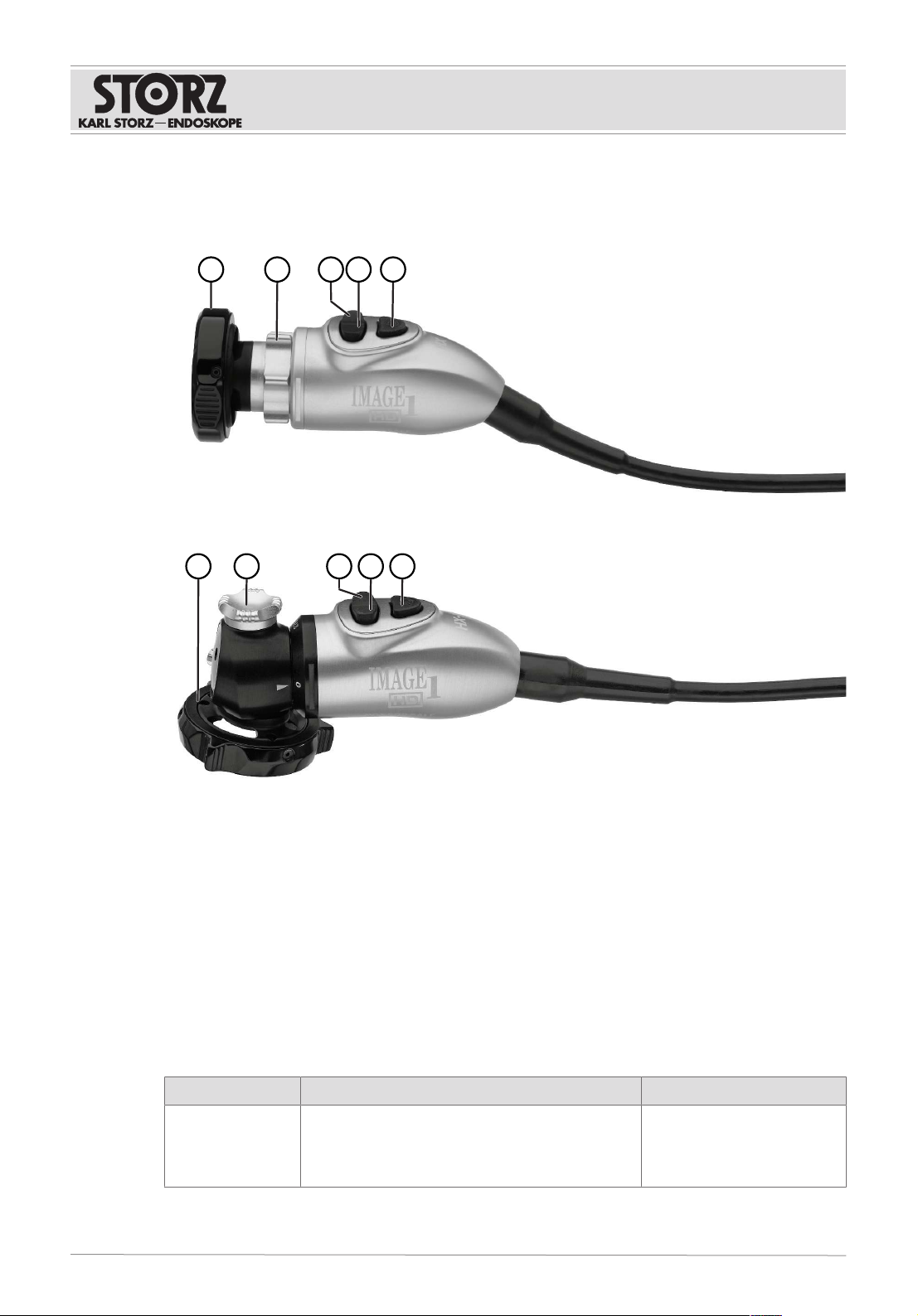
4.1 Product overview
4
123 5
IMAGE1S HX Camera Head (TH110)
4
123 5
IMAGE1S HX-P Camera Head (TH111)
1 Instrument coupler 4 Scroll up
Activate camera function
2 Focus ring/Focus wheel 5 Call up menu
Select
3 Scroll down
Activate camera function
4.2 Possible combinations
It is recommended that the suitability of the products for the intended procedure be checked prior to
use. Please note that the products listed here may not yet be available in all countries due to
differences in approval requirements.
Combination with camera control unit (CCU)
Camera head CCU LINK module
TH110
TH111
IMAGE1S CONNECT (TC200)
IMAGE1S CONNECTII (TC201)
TELE PACK+ (TP101)
TELECAMC3 (TC100)
IMAGE1S X-LINK (TC301)

Product description
Instructions for use • IMAGE1 S HX Camera Heads • NAM292_EN_V2.0_08-2022_IFU_CE-MDR 11
Combination with endoscopes or adaptors
The product can be connected to endoscopes or adaptors via the eyepiece connection.
4.3 Technical data
Description Value
Image sensor 1x1/3" CMOS
Image format 16:9
Image refresh rate 50/60Hz
Focal length 16mm
Dimensions (LxWxH) 100x36x35mm
Weight (without cable):
TH110
TH111
130g
142g
4.4 Symbols on the packaging
Symbol Meaning
Manufacturer
Date of manufacture
Medical device
Article no.
Serial number
Number of products in the product packaging
Unique Device Identifier
Consult the printed or electronic instructions for use
Note for the user to consult the instructions for use for important cautionary in-
formation such as warnings and precautions.
Unsterile

Product description
Instructions for use • IMAGE1 S HX Camera Heads • NAM292_EN_V2.0_08-2022_IFU_CE-MDR 12
Symbol Meaning
Fragile, handle with care
Federal (USA) law restricts this device to sale by or on the order of a physician.
CE marking
With this marking, the manufacturer declares the conformity of the product
with the applicable EU directives. A code number after the CE mark indicates
the responsible notified body.
The EU directives relevant to the product can be found in the EU Declaration
of Conformity, which can be requested from KARLSTORZ.
4.5 Ambient conditions
Storage/transport conditions
Temperature -10°C...60°C (14°F...140°F)
Relative humidity 20–95%
Operating conditions
Temperature 5°C...35°C (41°F...95°F)
Relative humidity
(non-condensing)
20–95%

Preparation
Instructions for use • IMAGE1 S HX Camera Heads • NAM292_EN_V2.0_08-2022_IFU_CE-MDR 13
5 Preparation
5.1 Unpacking the product
1. Carefully remove the product and accessories from the packaging.
2. Check the delivery for missing items and any possible damage.
3. In the case of damage, hidden defects, and short deliveries, document their nature and extent
and contact the manufacturer or supplier immediately.
5.2 Assembling the product
The product has an integrated instrument coupler and an integrated telescope.
1. Rotate the outer ring of the coupler clockwise and insert the endoscope eyepiece.
2. If the endoscope is connected to a pendulum camera head, make sure that the pendulum lock is
engaged.
3. Tighten the outer ring on the grasping mechanism.
4. Rotate the outer ring of the instrument coupler counterclockwise to tighten it.
5.3 Connecting the light cable
1. Tighten the knurled screw on the light cable by a quarter turn to connect the light cable.

Application
Instructions for use • IMAGE1 S HX Camera Heads • NAM292_EN_V2.0_08-2022_IFU_CE-MDR 14
6 Application
6.1 Adjusting the focus
The image display can be impaired by intense laser light.
1. Ensure that the correct video image is displayed on the monitor before starting the procedure.
2. Turn the focus ring to adjust the image sharpness on the camera lens.
IMAGE1S HX Camera Head (TH110)
IMAGE1S HX-P Camera Head (TH111)

Maintenance, servicing, repairs, and disposal
Instructions for use • IMAGE1 S HX Camera Heads • NAM292_EN_V2.0_08-2022_IFU_CE-MDR 15
7 Maintenance, servicing, repairs, and disposal
7.1 Repairs to the product
Repair work may only be performed by KARLSTORZ or by a company authorized by KARLSTORZ.
Please contact your local KARL STORZ subsidiary or authorized dealer (see the list of
subsidiaries).
Contaminated devices may not be shipped. To prevent contact infections and airborne infections,
products must first be decontaminated. KARLSTORZ reserves the right to send back contaminated
products.
7.2 Disposing of the product
The product meets the requirements of the Directive on Waste Electrical and Electronic Equipment
(WEEE).
Within the scope of application of this directive, KARLSTORZSE&Co.KG is responsible for the
proper disposal of this product.
1. The product must be disposed of in accordance with the applicable national laws and
regulations at a suitable collection point for the reprocessing of electrical and electronic
equipment.
2. Contact KARLSTORZSE&Co.KG, a KARLSTORZ branch or an authorized dealer to find out
the address of the collection point in your area.

Accessories and spare parts
Instructions for use • IMAGE1 S HX Camera Heads • NAM292_EN_V2.0_08-2022_IFU_CE-MDR 16
8 Accessories and spare parts
8.1 Accessories
Not all articles are available in all regions.
Article Order no.
Adaptor, autoclavable 533TVA
Dust cap for camera heads 6349190
Camera Cover, sterile, for single use, pack of 40 040112-40
Camera Cover, sterile, for single use, pack of 50 040113-50
Camera Cover, sterile, for single use, pack of 15 040114-15
Camera Cover, sterile, for single use, pack of 40 040115-40
Camera Cover, sterile, for single use, pack of 40 040169-40
Camera Cover, sterile, for single use, pack of 25 040170-25

Electromagnetic compatibility
Instructions for use • IMAGE1 S HX Camera Heads • NAM292_EN_V2.0_08-2022_IFU_CE-MDR 17
9 Electromagnetic compatibility
9.1 General notes on the operating environment
The product is suitable for use in professional healthcare settings. Professional healthcare facilities
include physician offices, dental offices, limited care facilities, freestanding surgical centers,
freestanding birth centers, multiple treatment facilities, hospitals (emergency rooms, patient rooms,
intensive care, surgical rooms, outside the HF-shielded room of an ME system for MRT).
The emission characteristics of this product make it suitable for use in industrial areas as well as
in hospitals (CISPR 11 Class A) and other professional healthcare environments. If it is used in a
residential environment (for which CISPR 11 Class B is normally required), the product may not
offer sufficient protection for radio transmission operation. The user might need to take
mitigation measures, such as relocating or re-orienting the product.
WARNING
Degradation of performance! Malfunction!
Portable RF communications equipment (including peripherals such as antenna cables and external
antennas) could result in degradation of the performance of the product.
Do not use portable communications equipment closer than 30 cm (12 inches) to any part of the
product, including cables.
9.2 Table 1 – Compliance level for immunity tests
Guidelines and manufacturer’s declaration– electromagnetic immunity
The product is intended for use in the electromagnetic environment specified below. The user of the
product should make sure that it is used in such an environment.
Interference im-
munity tests
EN/IEC60601 test level Compliance level Electromagnetic envi-
ronment – guidelines
Electrostatic dis-
charge (ESD) acc.
to IEC61000-4-2
±8kV contact discharge
±15kV air discharge
±8kV contact discharge
±15kV air discharge
Floors should be made of
wood, concrete, or cov-
ered with ceramic tiles. If
floors are covered with
synthetic material, the rel-
ative humidity must be at
least 30%.
Electrical fast tran-
sients/bursts acc.
to IEC 61000-4-4
±2kV for power lines
±1kV for input and out-
put lines
100kHz repetition
±2kV for power lines
±1kV for input and out-
put lines
100kHz repetition
The power supply quality
should be that of a typical
commercial or hospital
environment.
Surges acc. to IEC
61000-4-5
± 1kV voltage outer
conductor – outer con-
ductor
± 2kV voltage outer
conductor – ground
± 1kV voltage outer
conductor – outer con-
ductor
± 2kV voltage outer
conductor – ground
The power supply quality
should be that of a typical
commercial or hospital
environment.
Voltage dips, short
interruptions, and
voltage variations
acc. to
IEC61000-4-11
Voltage dip:
Dip to 0% for 1 cycle at
0° phase angle
Dip to 70% for 25/30 cy-
cles at 0° phase angle
Voltage dip:
Dip to 0% for 1 cycle at
0° phase angle
Dip to 70% for 25/30 cy-
cles at 0° phase angle
The power supply quality
should be that of a typical
commercial or hospital
environment. If the user
of the product requires
continued operation in

Electromagnetic compatibility
Instructions for use • IMAGE1 S HX Camera Heads • NAM292_EN_V2.0_08-2022_IFU_CE-MDR 18
Interference im-
munity tests
EN/IEC60601 test level Compliance level Electromagnetic envi-
ronment – guidelines
Dropout to 0% for 0.5
cycles @ 0°, 45°, 90°,
135°, 180°, 225°, 270°,
and 315° phase angles
Voltage interruption:
100% for 250/300cy-
cles
Dropout to 0% for 0.5
cycles @ 0°, 45°, 90°,
135°, 180°, 225°, 270°,
and 315° phase angles
Voltage interruption:
100% for 250/300cy-
cles
the event of interruptions
to the power supply net-
work, it is recommended
that the product be oper-
ated with an uninterrupt-
ible power supply or a
battery.
Magnetic field at
the power fre-
quency (50/60Hz)
acc. to IEC
61000-4-8
30A/m at 50Hz/ 60Hz 30A/m at 50Hz/ 60Hz If image distortion occurs,
it may be necessary to in-
stall the product further
from sources of electro-
magnetic fields or to in-
stall magnetic shielding.
Before the product is in-
stalled, the electromag-
netic field should be mea-
sured to ensure that it is
sufficiently low.
Immunity test acc.
to IEC61000-4–3
for radiated, radio-
frequency electro-
magnetic fields
3V/m 80MHz to
2.7GHz
* Refer to Table 2 for
wireless proximity RF
field test levels
3V/m 80MHz to
2.7GHz
Immunity to con-
ducted distur-
bances, induced by
radio-frequency
fields acc. to IEC
61000-4-6
3Vrms on 150kHz to
80MHz
1kHz 80% AM modula-
tion
6Vrms in ISM band
3Vrms on 150kHz to
80MHz
1kHz 80% AM modula-
tion
6Vrms in ISM band
9.3 Table 2 – Test levels for proximity fields from HF wireless
communications equipment
Test frequency
MHz
Frequency
band
MHz
Radio service Modulation Immunity
test level
V/m
Compliance
level
V/m
385 380 – 390 TETRA 400 Pulse modula-
tion 18Hz
27 27
450 430 – 470 GMRS 460,
FRS 460
FM ±5kHz de-
viation
1kHz sine
wave
28 28
710 704 – 787 LTE band 13
and 17
Pulse modula-
tion
217Hz
9 9
745
780

Electromagnetic compatibility
Instructions for use • IMAGE1 S HX Camera Heads • NAM292_EN_V2.0_08-2022_IFU_CE-MDR 19
Test frequency
MHz
Frequency
band
MHz
Radio service Modulation Immunity
test level
V/m
Compliance
level
V/m
810 800 – 960 GSM 800/900,
TETRA 800,
iDEN 820,
CDMA 850,
LTE band 5
Pulse modula-
tion
18Hz
28 28
870
930
1720 1700 – 1990 GSM 1800,
CDMA 1900,
GSM 1900,
DECT,
LTE band 1, 3,
4, 25,
UMTS
Pulse modula-
tion
217Hz
28 28
1845
1970
2450 2400 – 2570 Bluetooth,
WLAN 802.11
b/g/n,
RFID 2450,
LTE Band 7
Pulse modula-
tion
217Hz
28 28
5240 5100 – 5800 WLAN 802.11
a/n
Pulse modula-
tion
217Hz
9 9
5500
5785
9.4 Table 3 – Test levels for radiated and conducted immunity
tests
Guidelines and manufacturer’s declaration– electromagnetic immunity
The product is intended for use in the electromagnetic environment specified below. The user of the
product should make sure that it is used in such an environment.
Interference immunity
tests
EN/IEC60601 test
level
Compliance
level
Electromagnetic environ-
ment – guidelines
Conducted HF distur-
bances acc. to IEC
61000-4-6
3Vrms
150kHz to 80MHz
3Vrms Portable and mobile HF
communications equipment
should be used no closer to
any part of the product, in-
cluding cables, than the rec-
ommended separation dis-
tance calculated from the
equation applicable to the
frequency of the transmitter.
Recommended separation
distances:
d = 1.2√P
Where P is the rated power
of the transmitter in watts
[W] according to the infor-
mation provided by the
Radiated HF distur-
bances acc. to IEC
61000-4-3
3V/m
80MHz to 2.5GHz
3V/m

Electromagnetic compatibility
Instructions for use • IMAGE1 S HX Camera Heads • NAM292_EN_V2.0_08-2022_IFU_CE-MDR 20
Interference immunity
tests
EN/IEC60601 test
level
Compliance
level
Electromagnetic environ-
ment – guidelines
transmitter manufacturer and
d is the recommended sepa-
ration distance in meters [m].
Field strengths from fixed HF
transmitters as determined
by an electromagnetic site
survey a should be less than
the compliance level in each
frequency range b.
d = 1.2√P
80MHz to 800MHz
d = 2.3√P
800MHz to 2.5GHz
Interferences may occur in
the vicinity of equipment
marked with the following
symbol:
Note: At 80MHz and 800MHz, the higher frequency range applies.
Note: These guidelines may not apply in all situations. The propagation of electromagnetic waves is
affected by absorptions and reflections of buildings, objects, and people.
a Field strengths from fixed transmitters, e.g., base stations for radio (cellular/cordless) telephones
and land mobile radios, amateur radio, AM and FM radio broadcast, and TV broadcast cannot be
predicted theoretically with accuracy. To assess the electromagnetic environment due to fixed trans-
mitters, an electromagnetic site survey should be considered. If the measured field strength at the
location where the device is used exceeds the above compliance levels, the device should be moni-
tored to ensure proper function. If abnormal performance is observed, additional measures may be
necessary, such as re-orienting or relocating the product.
b Over the frequency range from 150kHz to 80MHz, field strengths should be less than 3V/m.
9.5 Table 4 – Emission class and group
Guidelines and manufacturer’s declaration– Electromagnetic emissions
The product is intended for use in such an environment as specified below. The customer or user of
the product should ensure that it is used in such an environment.
Interference emission measure-
ments
Compliance Electromagnetic environment –
guidelines
RF emissions acc. to CISPR 11 Group 1 The device uses RF energy only for its
internal function. Therefore, its RF
emissions are very low and are not
likely to cause any interference in
nearby electronic equipment.
RF emissions acc. to CISPR 11 ClassA The device is suitable for use in all es-
tablishments other than domestic and
those directly connected to the public
Emission of harmonic oscillations
acc. to IEC61000-3-2
ClassA
Other manuals for Image1 S H3-Z FI TH 102
8
This manual suits for next models
3
Table of contents
Other Storz Digital Camera manuals


