Strasbaugh nTellect 7AF User manual

nTellect
(Model 7AF)
Wafer Grinder
Operations and
Maintenance Manual
S T R A S B A U G H
825 Buckley Road
San Luis Obispo, California 93401
Phone (805) 541-6424
Fax: (805) 541-6425

Copyright © 1998, 2002-2004 by Strasbaugh. All rights reserved.
Document prepared by: Technical Publications Group

Operations and Maintenance Manual Table of Contents
Version 1.2 -June 2004 TOC -1
TABLE OF CONTENTS
CHAPTER 1 -INTRODUCTION
About this Manual 3
Contents and Purpose 3
Update Sections 3
Document Conventions 4
Touch Screen 4
Control Panel 4
At the PC Keyboard 5
Step-By-Step Instructions 5
About the Machine 6
Mechanical Components 6
Electrical Distribution and Control 7
Safety 9
General Operation 9
Visual Hazard Alerts 10
Hazard Magnitude Levels 10
Three-Panel Alert Graphics 10
Sprayer Use 13
Safety Interlock Door Switches 13
Guarantee/Warranty Certificate 14

Strasbaugh nTellect (Model 7AF) Wafer Grinder
TOC -2Version 1.2 -June 2004
CHAPTER 2 -INSTALLATION
Overview 3
Step 1 -Unpacking/Inspection 4
Preparation for Installation 5
Step 2 -Machine Placement 6
For Manufacturing Locations with a Wide Access Door 7
(70 Inches or Greater) 7
For Manufacturing Locations with a Narrow Access Door 8
(Greater than 50 Inches but Less than 70 Inches) 8
Step 3 -Leveling the Two Machine Sections 9
Summary 9
A. Grinding Area Cabinet Base Leveling Procedure 10
Leveling Feet 10
Leveling Procedure 10
B. Handling Area Cabinet Base Leveling Procedure 16
Leveling Casters 16
Leveling Procedure 16
Step 4 -Utility Requirements 20
Step 5 -Connecting Utilities to External Sources 21
Electrical 23
Clean Dry Air 24
Vacuum 24
Vacuum Clean Dry Air 25
De-Ionized Water 25
Industrial Waste 26
Exhaust 26
Air Bearing Spindle Motor Cooling Water In/Out 26
Step 6 -Initial alignments -Completing the Installation 27
Initial Adjustments -Grinding Area 27
Initial Adjustments -Handling Area 28
Robot Software Calibration Procedures 28

Operations and Maintenance Manual Table of Contents
Version 1.2 -June 2004 TOC -3
CHAPTER 3 -PHYSICAL DESCRIPTION
Overview 3
Cabinetry 4
Door Numbering System 4
Service Doors (Doors 7, 8 , 9, 10, 11, 12, 13, 14, 15, 16, 17, 18, 19, and 21) 4
Disconnect Enclosure Door (Door 20) 4
Operator Doors (Doors 5 and 6) 5
Cassette Turrets (Doors 1, 2, 3, and 4) 5
Interlock Safety Switches 5
Machine Views 7
Subassemblies 15
Grinding Area 16
Wafer Handling Area 17
Control Panel and Emergency Off Buttons 18
Control Panel 18
Emergency Off Buttons 19
Control Computer 20
Monitor -Touch Screen 20
Keyboard 20
To Plug in the Keyboard: 20
Frequently Used Keys 21
User Interface 22
Menu Tree 22
Main Menu 23
Home Machine Menu 24
Grind Cycle Menu 25
Edit Recipes (Wafer Recipes) Menu 26
Wheel and Chuck (Truing and Dressing) Recipes Menu 27
Dress Cycle Menu 28
Machine Maintenance Menu 29
Output Control/Input Status Menu 30
Machine (Calibration) Setup Entry Menu 31

Strasbaugh nTellect (Model 7AF) Wafer Grinder
TOC -4Version 1.2 -June 2004
CHAPTER 4 -MECHANICAL DESCRIPTION
Overview 3
Grinding Area 3
Bridge Assembly 3
Spindle Assemblies 4
Coarse/Fine Spindles 4
Left/Right Work Chucks 5
Air Bearing Spindles 5
Left/Right Digital Measurement Probes 6
Left/Right Conditioning Arms 6
Wafer Handling Area 7
Robot 7
Pre-Aligner 8
Spin-Rinse Station 9
Send 1, Send 2, Receive 1, Receive 2 Cassette Access Turret Assemblies 9
CHAPTER 5 -CONTROL SYSTEM DESCRIPTION
Control Computer3
Servo Control 3
Servo Amplifier 5
I/O and Interface System 6
Robot and Controller, 7
Pre-Aligner, and Controller 7
Digital Measurement Probes 8

Operations and Maintenance Manual Table of Contents
Version 1.2 -June 2004 TOC -5
CHAPTER 6 -POWER DISTRIBUTION
Introduction 3
AC Distribution 3
DC Distribution 4
Power Up 4
Interlocks 6
CHAPTER 7 -PLUMBING DESCRIPTION
Clean Dry Air System 4
Vacuum System 5
Water System 6
Exhaust System 7
Drain System 7
CHAPTER 8 -OPERATOR FUNCTIONS
Overview 4
Menus Used in Basic Operation 6
Menu Tree 6
The Main Menu 7
The Home Machine Menu 9
The Grind Cycle Menu 15
The Dress Cycle Menu 19
Auto Grind Cycle Sequence 23
Event Sequence 24

Strasbaugh nTellect (Model 7AF) Wafer Grinder
TOC -6Version 1.2 -June 2004
Basic Operation 26
Summary 26
Problems and Error Messages 26
1 -Powering Up 27
2 -Homing the Machine 30
Check for Obstructions and Display the Home Machine menu 31
Home the Machine Automatically 32
Home Individual Servos Manually 34
3 -Checking Utilities 36
4 -Referencing the Chucks 37
5 -Running an Automatic Grind Cycle 42
Display the Grind Cycle menu 43
Select the Desired Recipe and Grind 43
Compare the Stored Recipe Values with the Parameter Values Received from the Process Supervisor 45
Prepare the Cassettes and Start the Cycle 47
While the Cycle Is Running, Monitor the Status Screen Display Values 49
If There’s a Problem, Halt (Interrupt) or Stop (Cancel) the Cycle 51
When the Last Wafer Has Been Processed 52
Truing and Dressing the Grind Wheels and Work Chucks 53
Display the Dress Cycle Menu 54
Grind Wheel Dressing and Truing 57
Select the Wheel and the Treatment Desired 57
Compare the Stored Recipe Values with the Parameter Values Received from the Process Supervisor 58
Start the Cycle 60
While the Cycle Is Running, Monitor the Status Screen Display Values 61
If There's a Problem, Stop (Cancel) the Cycle 62
When the Start Cycle and Stop Cycle Buttons Begin to Flash 62
Chuck Dressing and Truing 63
Select the Chuck and the Treatment Desired 63
Compare the Stored Recipe Values with the Parameter Values Received from the Process Supervisor 64
Start the Cycle 65
While the Cycle Is Running, Monitor the Status Screen Display Values 66
If There’s a Problem, Stop (Cancel) the Cycle 67
When the Start Cycle and Stop Cycle Buttons Begin to Flash 67
Using the Probes 68
Raising and Lowering the Probes 68
Referencing the Probes 70
Measuring the Thickness of an Item on the Work Chuck 73
Operator Daily Preventive Maintenance Schedule 75
Light Tower Operation 77
Idle: Green Flashing, No Alarm Sounds 77
Running: Green Steady, No Alarm Sounds 77
Needs Assistance: Yellow Flashing, Alarm Sounds 78
Needs Assistance, Acknowledged: Yellow Steady, No Alarm Sounds 78
Fault: Red Flashing, Alarm Sounds 79
Fault, Acknowledged: Red Steady, No Alarm Sounds 80

Operations and Maintenance Manual Table of Contents
Version 1.2 -June 2004 TOC -7
CHAPTER 9 -MACHINE SETUP
Overview 3
Wafer Recipes Menu 5
Grinding Sequence 7
Recipe Parameter Settings and Information Available at the Wafer Recipes Menu 9
Coarse and Fine Grind Recipe Steps and Parameters 9
Wafer Parameters 12
Estimated Throughput in Wafers Per Hour 12
Example Recipes 13
Choices Available at the Wafer Recipes Menu 14
Using the Wafer Recipes Menu 16
Summary 16
Step 1 -Select the Name of the Recipe 16
Step 2 -Enter the Coarse Grind Data 17
Step 3 -Enter the Fine Grind Data 18
Step 4 -Set the Wafer Parameters 18
Step 5 -Quit and Save Changes 19
Wheel and Chuck Recipes Menu 20
Recipe Parameter Settings and Information Available at the Wheel and Chuck Recipes Menu 23
Dress and True Recipe Steps and Parameters 23
Fine Wheel Parameters 24
Grind Wheel Example Recipes 25
Work Chuck Example Recipes 26
Choices Available at the Wheel and Chuck Recipes Menu 27
Using the Wheel and Chuck Recipes Menu 29
Summary 29
Step 1 -Select the Name of the Recipe 29
Step 2 -Enter the Dress and True Recipe Data 30
Step 3 -Quit and Save Changes 32
Pre-Aligner Second Flat Sensing -OPTION 32

Strasbaugh nTellect (Model 7AF) Wafer Grinder
TOC -8Version 1.2 -June 2004
CHAPTER 10 -PREVENTIVE MAINTENANCE
SCHEDULES
Overview 3
Daily
Preventive Maintenance Schedule 4
7-Day or 5,000 Wafers
Preventive Maintenance Schedule 7
30-Day or 20,000 Wafers
Preventive Maintenance Schedule 11
180-Day or 80,000 Wafers
Preventive Maintenance Schedule 12
365-Day or 160,000 Wafers
Preventive Maintenance Schedule 14
CHAPTER 11-MECHANICAL MAINTENANCE
PROCEDURES
Overview 4
Manual Control of Assemblies 6
Menus Used in the Mechanical Maintenance Procedures 6
Manual Movement of the Bridge with Machine Power OFF 7
Initial Alignments 8
Grinding Area 8
Summary 9

Operations and Maintenance Manual Table of Contents
Version 1.2 -June 2004 TOC -9
I. Before You Begin 10
II. Level the Horizontal Rails of the Bed 15
III.Level the Lower Left and Right Spindle Assemblies 19
IV. Mount the Fringe Plates to the Lower Spindle Assemblies and Adjust 28
V. Adjust Upper Spindle Assemblies to Positions Parallel with Lower Right Spindle 34
VI. Adjust Lower Left Spindle Assembly Parallel to Upper Spindle Assemblies 43
VII. Bridge Left/Right Travel Proximity Sensor Adjustments 48
VIII. Spindle Z Travel Proximity Sensor Adjustments 61
IX. When Grinding Area Initial Adjustments are Successful 68
Handling Area 69
Summary 69
I. Before You Begin 70
II. Level the Robot 72
III. Level the Robot End Effector 74
IV. Align the Pre-Aligner with the Robot 79
V. Align the Spin-rinse Station with the Robot 84
VI. Level the Four Cassette Platforms (Turrets) 92
VII. Adjust the Bed to a Position Parallel to the Robot 109
VIII. When Grinding Area and Handling Area Initial Alignments are Complete 114
Bridge 115
Horizontal Travel Belt Adjustment 115
Spindles 118
Z Travel Belt Adjustment 118
Changing the Grind Wheels 120
Changing the Work Chucks 127
Digital Measurement Probes 134
Assembly Height Adjustments 134
Robot 140
Pre-aligner 141
Spin-Rinse Station 142
Spin-Rinse Motor Drive Belt Adjustment 142
Spin-Rinse Chuck Up/Down Cylinder Reed Switch Adjustments 144
Cassette Turrets 149
Rotary Actuator Sensor Load/Robot Position Adjustments 149
A. Before You Begin 149
Load Position 150
B. Check All Four Turret Switches and Record Results 150
C. Adjust the Load Position Sensors 152
D. Test the New Positioning 153
Robot Position 153
E. Check All Four Turret Sensors and Record Results 153
F. Adjust the Robot Position Sensors 155
G. Test the New Positioning 156
H. When Satisfactory Adjustment Is Achieved 156

Strasbaugh nTellect (Model 7AF) Wafer Grinder
TOC -10 Version 1.2 -June 2004
CHAPTER 12-SOFTWARE CALIBRATION
PROCEDURES
Overview 3
Menus Used in Maintenance and Calibration 4
Machine Maintenance Menu 4
Information Available at the Maintenance Menu 5
Choices Available at the Machine Maintenance Menu 7
Using the Machine Maintenance Menu's Manual Controls -An Example 14
Output Control / Input Status Menu 16
Information and Choices Available at the Output Control/Input Status Menu 17
Using the Output Control/Input Status Menu's Manual Controls -An Example 24
Machine (Calibration) Setup Entry Menu 26
Information and Choices Available at the Machine Setup Entry Menu 28
Using the Machine Setup Entry Menu -An Example 30
Robot (and Pre-Aligner) Setup and Calibration 32
Robot Coordinates 32
Robot (and Pre-Aligner) Commands 33
Robot / Cassette Turret Position Calibration 38
Theta 38
Radius 39
Z-Axis 40
Setting and Saving the New Coordinates 42
Work and Spin Chuck Home Index Calibration 43
Machines with Home Index Hardware Installed 44
Machines Without Home Index Hardware Installed 44

Operations and Maintenance Manual Table of Contents
Version 1.2 -June 2004 TOC -11
CHAPTER 13 -PNEUMATIC ADJUSTMENTS
Overview 3
Clean Dry Air 5
Incoming Clean Dry Air 6
Left/Right Grind Chamber Seals 7
Left/Right Chuck Conditioning Arms Up 8
Left/Right Chuck Conditioning Arms Engage 13
Left/Right Chuck Conditioning Arms Brush Rotation 13
Left/Right Chuck Conditioning Arms Downforce 14
Automatic Lubricator 14
Send 1 Cassette Turret Rotary Actuator 15
Send 2 Cassette Turret Rotary Actuator 18
Receive 1 Cassette Turret Rotary Actuator 19
Receive 2 Cassette Turret Rotary Actuator 20
Left/Right Measurement Probes 21
Spin Station Spindle Up/Down 22
Spin Station Lid Up/Down 25
Spin Station Brush Arm Park 28
Robot Flipper 29
Lower (Work Chuck) Air Bearing Spindles 32
Upper (Grind Wheel) Air Bearing Spindles 32
Turret Hydraulic Accumulator Reservoirs 33
Vacuum 34
Left/Right Grind Chamber Seal Vacuum 34
Left/Right Work Chuck Vacuum 34
Pre-aligner Vacuum 35
Rinse Spin Chuck Vacuum 35
Robot End Effector Vacuum 35
D.I. Water 36
Left Work Chuck Cutting Water 36
Right Work Chuck Cutting Water 40
Left/Right Work Chuck D.I. Water Backflush 41
Spin Station Wafer Clean 46
Blow Off 47
Left/Right Work Chuck Air Blow Off 47
Spin Station Wafer Blow Off 48
Robot End Effector Blow Off 48
Spindle Cooling Water for the Four Air Bearing Spindles 49
Coarse Spindle Cooling Water 49
Fine Spindle Cooling Water 51
Left (Work Chuck) Spindle Cooling Water 52
Right (Work Chuck) Spindle Cooling Water 53

Strasbaugh nTellect (Model 7AF) Wafer Grinder
TOC -12 Version 1.2 -June 2004
CHAPTER 14 -TROUBLESHOOTING
Overview 4
Messages Displayed on the Control Computer Screen Take Precedence! 4
Assumption 4
Work and Spin Chuck Homing Hardware 5
Machine Operation Checkout 6
Normal Operating Conditions and Strategies for Maintaining Them 8
Grind Force 8
Motor Current 8
Probe 8
Manual Dressing and Truing 9
Automatic Dressing and Truing 9
Visual Wafer Inspection -Identifying and Correcting Six Grind Process Problems 10
Fault Messages 14
Air Pressure (PSI) 15
Coarse Spindle PSI 15
Fine Spindle PSI 15
Left Chuck PSI 15
Right Chuck PSI 15
Cassettes 15
Cross Slot/Cassette 15
New Receive Cassette 15
New Send Cassette 15
Chucks 16
Rotational Home 16
Left Chuck Home 16
Right Chuck Home 16
Conditioning Arm Position 16
Left Condition Arm 16
Right Condition Arm 17
Coolant 17
Left Chuck Coolant 17
Right Chuck Coolant 17
Counterbalance 17
Counterbalance 17
Doors and Panels 18
Operator Door Open 18
Service Panels Open 18
Exhaust—IMPORTANT SAFETY INFORMATION! 18
Exhaust Fail 18
Force 18
Coarse Force Limit 18
Fine Force Limit 19
Grind Abort 20
Grind Abort: Unsafe! 20
Grind Seal 21
Left Grind Seal 21
Right Grind Seal 21

Operations and Maintenance Manual Table of Contents
Version 1.2 -June 2004 TOC -13
Grind Wheel 21
Coarse Wheel is Down 21
Fine Wheel is Down 21
Load Cell 22
Coarse Z Load Cell 22
Fine Z Load Cell 22
Prealigner 22
Prealigner Error 22
Probes 23
Left Probe 23
Right Probe 23
Left Probe is Down 23
Right Probe is Down 23
Reference 24
Bad Reference 24
Robot Communication 24
Robot Communication 24
Service Panel: Abort 24
Service Panel: Abort 24
Servo 25
Bridge Servo 25
Coarse Z Servo 25
Fine Z Servo 25
Left Chuck Servo 25
Right Chuck Servo 26
Robot Servo 26
Spin Station Servo 26
Coarse Spindle Servo 26
Fine Spindle Servo 27
Servo Water 27
Coarse Servo H20 27
Fine Servo H20 27
LT Chuck Servo H20 27
RT Chuck Servo H20 27
Spin Station 28
Spin Chuck Up/Down 28
Spin Lid Up/Down 28
Spin Station Home 28
Thickness 28
Thickness Limit 28
Turrets 29
Hand Close Turrets 29
Vacuum 29
Aligner Vacuum (Prealigner) 29
Left Chuck Vacuum 29
Left Chuck VacAbort 29
Right Chuck Vacuum 30
Right Chuck VacAbort 30
Robot Chuck Vacuum 30
Spin Station Vacuum 30

Strasbaugh nTellect (Model 7AF) Wafer Grinder
TOC -14 Version 1.2 -June 2004
CHAPTER 15-SOFTWARE AND CONTROL COMPUTER
MAINTENANCE
Overview 3
Messages Displayed on the Control Computer Screen Take Precedence! 3
Assumption 3
Backup and Recovery 4
Software Version Required 4
Backup 4
Restore 5
Protecting Recipe Files--Temporary Security Measures 7
Software Version Required 7
Protecting Recipes 7
Removing Protection from Recipes 8
Grind Data Files 9
File Structure 9
Example of a Grind Data File 10
Operation 11

Operation and Maintenance Manual Model 7AF Wafer Grinder
Appendices
Appendix A Calibration Variables Listing
Appendix B Engineering Drawings (bound under separate cover)
Appendix C Customer Parts List
Appendix D Electrical Input/Output System Address List
Appendix E Vacuum Station
Appendix F Maintenance Log Sheets
Appendix G Manufacturers' Documentation Sheets
Version 1.2 - June 2004 TOC - 13

Strasbaugh Table of Contents
List of Figures
Figure 2-1 Top View of Wafer Handling Section with
References to Procedure Steps 2-18
Figure 2-2 Side View Detail of Alignment Leg and Its
Adjacent Caster 2-19
Figure 2-3 Utility Connections 2-23
Figure 3-1 Model 7AF Wafer Grinder - Front View 3-7
Figure 3-2 Left Side View 3-9
Figure 3-3 Right Side View 3-11
Figure 3-4 Rear View 3-13
Figure 3-5 Wafer Grinder Subassemblies 3-15
Figure 3-6 Control Panel 3-18
Figure 3-7 Menu Tree 3-22
Figure 3-8 Main Menu 3-23
Figure 3-9 Home Machine Menu 3-24
Figure 3-9 Grind Cycle Menu 3-25
Figure 3-11 Edit Recipes (Wafer Recipes) Menu 3-26
Figure 3-12 Wheel and Chuck Recipes Menu 3-27
Figure 3-13 Dress Cycle Menu 3-28
Figure 3-14 Machine Maintenance Menu 3-29
Figure 3-15 Output Control/Input Status Menu 3-30
Figure 3-16 Machine Setup Entry Menu 3-31
Figure 8-1 Menu Tree 8-5
Figure 8-2 Main Menu 8-6
Figure 8-3 Home Machine Menu 8-8
Figure 8-4 Grind Cycle Menu 8-14
Figure 8-5 Dress Cycle Menu 8-19
Figure 8-6 Main Menu at Power Up 8-28
Figure 8-7 Home Machine Menu 8-30
Figure 8-8 Grind Cycle Menu 8-42
Figure 8-9 Example of a Coarse Grind Recipe 8-44
Figure 8-10 Example of a Fine Grind Recipe 8-45
Figure 8-11 Dress Cycle Menu 8-53
Figure 8-12 Example of a Coarse Wheel Dressing Recipe 8-57
Figure 8-13 Example of a Fine Wheel Dressing Recipe 8-57
Figure 8-14 Example of a Coarse Wheel Truing Recipe 8-58
Figure 8-15 Example of a Fine Wheel Truing Recipe 8-58
TOC - 16 Version 1.2 - June 2004

Operation and Maintenance Manual Model 7AF Wafer Grinder
Figure 8-16 Example of a Work Chuck Dressing Recipe 8-63
Figure 8-17 Example of a Work Chuck Truing Recipe 8-63
Figure 9-1 Wafer Recipes Menu 9-6
Figure 9-2 Wheel and Chuck Recipes Menu 9-21
Figure 11-1 Lower Spindle Side to Side Adjustment 11-20
Figure 11-2 Lower Spindle Front to Rear Adjustment 11-22
Figure 11-3 Sketch of Stacking Pattern for Spring Washers
Used with the Fringe Plate Tools 11-27
Figure 11-4 Upper Spindle Probe Reading Points 11-35
Figure 11-5 Upper Spindle Side to Side Adjustment 11-36
Figure 11-6 Upper Spindle Front to Rear Adjustment 11-37
Figure 12-1 Machine Maintenance Menu 12-5
Figure 12-2 Output Control / Input Status Menu 12-18
Figure 12-3 Machine Setup Entry Menu 12-29
Figure 12-4 Top View of Robot Theta Positioning at
Cassette Turret 12-40
Figure 12-5 Top View of Radial Positioning of Robot 12-41
Figure 12-6 Top View of Z-Axis Positioning of Robot 12-42
Figure 14-1 Wafer Surface Finish Examples 14-11
Figure 14-2 Cross-Hatching on the Wafer Edge 14-12
Figure 14-3 Blue-Blacking or Burning 14-12
Figure 14-4 Circular Marks Around Center of Wafer 14-13Figure 14-5 Cross-Hatching at the Center of the Wafer 14-13
Figure 14-6 Chatter Marks on the Wafer Edge 14-14
Figure 14-7 Star Crack 14-14
Figure 15-1 Grind Data Transfer to Diskette 15-12
Version 1.2 - June 2004 TOC - 17
Strasbaugh Table of Contents
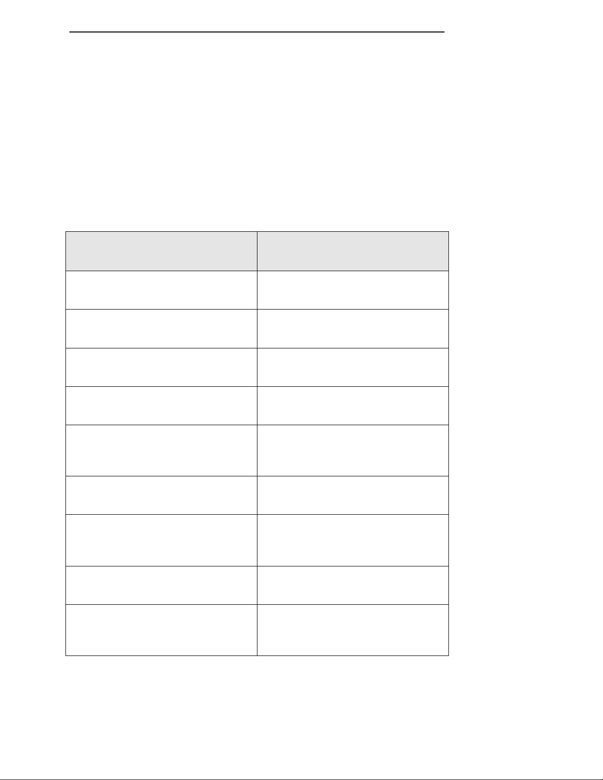
Menu Information Locator
The table below lists the 7AF software menus alphabetically together
with the location(s) in the Operation and Maintenance manual at
which detailed information for each may be found.
Menu Where to Find Details - Manual
Location(s)
DRESS CYCLE MENU • Ch. 8 - Operator Functions
GRIND CYCLE MENU • Ch. 8 - Operator Functions
HOME (MACHINE) MENU • Ch. 8 - Operator Functions
MACHINE MAINTENANCE MENU • Ch. 12 - Software Calibration
MACHINE (CALIBRATION) SETUP
ENTRY MENU • Ch. 12 - Software Calibration
MAIN MENU • Ch. 8 - Operator Functions
OUTPUT CONTROL/INPUT STATUS
MENU • Ch. 12 - Software Calibration
WAFER RECIPES MENU • Ch. 9 - Machine Setup
WHEEL AND CHUCK RECIPES
MENU • Ch. 9 - Machine Setup
TOC - 18 Version 1.2 - June 2004
Table of contents
Other Strasbaugh Industrial Equipment manuals


