Siko SGL Series Operation manual
SGL... Datum 21.11.2008 Art.Nr. 81383 Änd. Stand 369/08 1
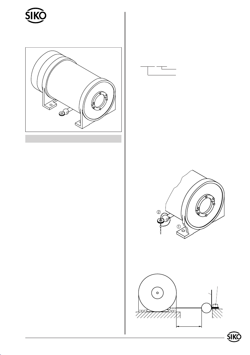
Abb. 1: Montage
Abb. 2: Messbereich
Messbereich
max. Auszugslänge
Aufkleber
Schraube M8
DEUTSCH
1. Gewährleistungshinweise
Lesen Sie vor der Montage und der Inbetriebnahme
dieses Dokument sorgfältig durch. Beachten Sie zu
Ihrer eigenen Sicherheit und der Betriebssicherheit
alle Warnungen und Hinweise.
Ihr Produkt hat unser Werk in geprüftem und be-
triebsbereitem Zustand verlassen. Für den Betrieb
gelten die angegeben Spezifikationen und die
Angaben auf dem Typenschild als Bedingung.
Garantieansprüche gelten nur für Produkte der
Firma SIKO GmbH. Bei dem Einsatz in Verbindung
mit Fremdprodukten besteht für das Gesamtsystem
kein Garantieanspruch.
Reparaturen dürfen nur im Werk vorgenommen
werden. Für weitere Fragen steht Ihnen die Firma
SIKO GmbH gerne zur Verfügung.
2. Sicherheitshinweise
Bedingt durch die große Auszugslänge sowie durch
den funktionell erforderlichen Federmotor ist eine
Verletzungsgefahr durch unsachgemäße Handha-
bung bzw. nachlässige Montage gegeben.
Das Seil darf nie lose zurückschnellen!
Seil nicht durch die Hand/Finger gleiten (bremsen)
lassen. Dies kann zu Verletzungen (z.B. Verbren-
nungen) führen!
Der Gefahrenbereich muss für Montage-/ Repara-
turarbeiten abgesichert werden!
Auf die Verwendung eines Seiles muss evtl.
•
•
•
•
•
•
•
•
hingewiesen werden (Verletzungs- und Funkti-
onsschutz). Unbefugter Zugang für Mensch und
Tier sollte verhindert werden.
3. Identifikation
Das Typenschild zeigt den Gerätetyp mit Varianten-
nummer. Die Lieferpapiere ordnen jeder Varianten-
nummer eine detaillierte Bestellbezeichnung zu.
z.B. SGL135-0023
Varianten-Nr.
Geräte-Typ
4. Mechanische Montage
Die Montage darf nur gemäß der angegebenen IP-
Schutzart vorgenommen werden. Diese wird durch
den angebauten Messwertgeber bestimmt, jedoch
nicht höher als ähnl. IP40. Der Seilzuggeber muss
ggfs. zusätzlich gegen schädliche Umwelteinflüs-
se, wie z.B. Spritzwasser, Staub, Schläge, Tempe-
ratur geschützt werden.
Der Seilzuggeber ist ein hochwertiges Messsystem für
den Anbau auf eine ebene Montagefläche (Abb. 1).
Vier Durchgangslöcher, für Schrauben M8, dienen
zur Befestigung auf der Montagefläche (1).
Entfernen Sie den als Transportsicherung ange-
brachten Kabelbinder (2).
•
•
Benutzerinformation
SGL...
Seilzuggeber
Das Seilende bzw. das Seil muss bis an die vor-
gesehene Befestigungsstelle ausgezogen werden.
Möglichst im eingefahrenen Zustand befestigen
(geringste Zugspannung auf dem Seil). Das Seil
darf dabei nicht verdreht werden.
•
2 SGL... Datum 21.11.2008 Art.Nr. 81383 Änd. Stand 369/08
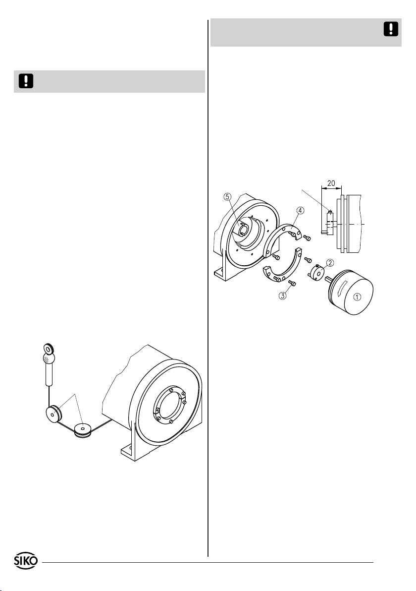
Abb. 3: Umlenkrolle
Umlenkrollen
Abb. 4: Montage eines Gebers
Schraubendreher DIN 911
SW1.5 verwenden
Seilende mit z.B. einer Schraube M8 befestigen
(Abb. 2).
Ein dreimaliger Auszug des Messweges -unter
Einsatzbedingungen- muss vor der Inbetriebnahme
des Messsystems durchgeführt werden.
Achtung! Die maximale Auszugslänge des Seils
darf nicht überschritten werden.
Handhabung des Seils
Um den Seilausgang nicht zu zerstören und da-
durch die Lebensdauer zu verringern, muss das Seil
lotrecht zum Seilausgang geführt werden.
Beim Seilauszug darf das Seil nicht lose zurück-
schnellen, da es sich auf der Seiltrommel im Ge-
häuse korrekt aufwickeln muss. Das Seil muss im-
mer, durch die Federkraft, gespannt sein.
Der am Seilende hängende Aufkleber ist am Seil-
befestigungsort sichtbar anzubringen (Abb. 2).
Für eine korrekte Funktion darf das Seil nicht ge-
quetscht oder geknickt werden.
Umlenkrolle (Zubehör z.B. SIKO Typ UR)
Wenn das Seil nicht lotrecht zum Seilausgang be-
festigt werden kann, ermöglicht der Einsatz einer
Umlenkrolle denn Auszug in jede beliebige Rich-
tung (Abb. 3).
Die Umlenkrolle muss parallel zum Seil montiert
werden.
Starke Schmutzbildung ist im Bereich der Um-
lenkrolle zu vermeiden. Die Funktion muss in
regelmäßigen Abständen kontrolliert werden.
•
•
•
•
Anlauf- und Betriebsdrehmoment des Gebers
dürfen den maximal zulässigen Wert von 3 Ncm
nicht überschreiten.
Entfernen Sie die Schrauben (3) und die Ser-
voflansche (4). Dahinter befindet sich der
Mitnehmer (2).
Prüfen Sie die Übereinstimmung der Anschlussma-
ße des Gebers (1) und des Mitnehmers (2).
Mitnehmer (2) auf Geberwelle schieben (Maß 20)
und mit Gewindestift befestigen.
Geber inkl. Mitnehmer in einen Schlitz des La-
gerrohres (5) schieben.
Durch gleichmäßiges Festziehen der Schrauben (3)
an den Servoflanschen wir der Geber montiert. Die
Montage muss spannungsfrei erfolgen!
•
•
•
•
•
•
Umlenkrollen reduzieren die Lebensdauer des
Seiles.
5. Montage eines Messwertgebers
Das Seilzugsystem ist für die Montage eines Inkre-
mental- oder Absolutwertgeber vorbereitet (Abb. 4).
•
Der nominelle Trommelumfang beträgt 400mm.
Durch Programmieren (Anpassen) der Folgeelek-
tronik oder bei Verwendung eines programmier-
baren Gebers kann die Messgenauigkeit optimiert
werden. Bei einem Neugerät kann -auf gesonderte
Bestellung- ein Messprotokoll mitgeliefert werden.
In Serviceintervallen (ca. 1 Jahr) sollten die
Anpassungen überprüft werden.
6. Justage
Zur Justage des Messwertgebers, die Schrauben
(3) lösen und Geber (1) in Pfeilrichtung drehen.
Die Schrauben wieder festziehen.
•
SGL... Datum 21.11.2008 Art.Nr. 81383 Änd. Stand 369/08 3
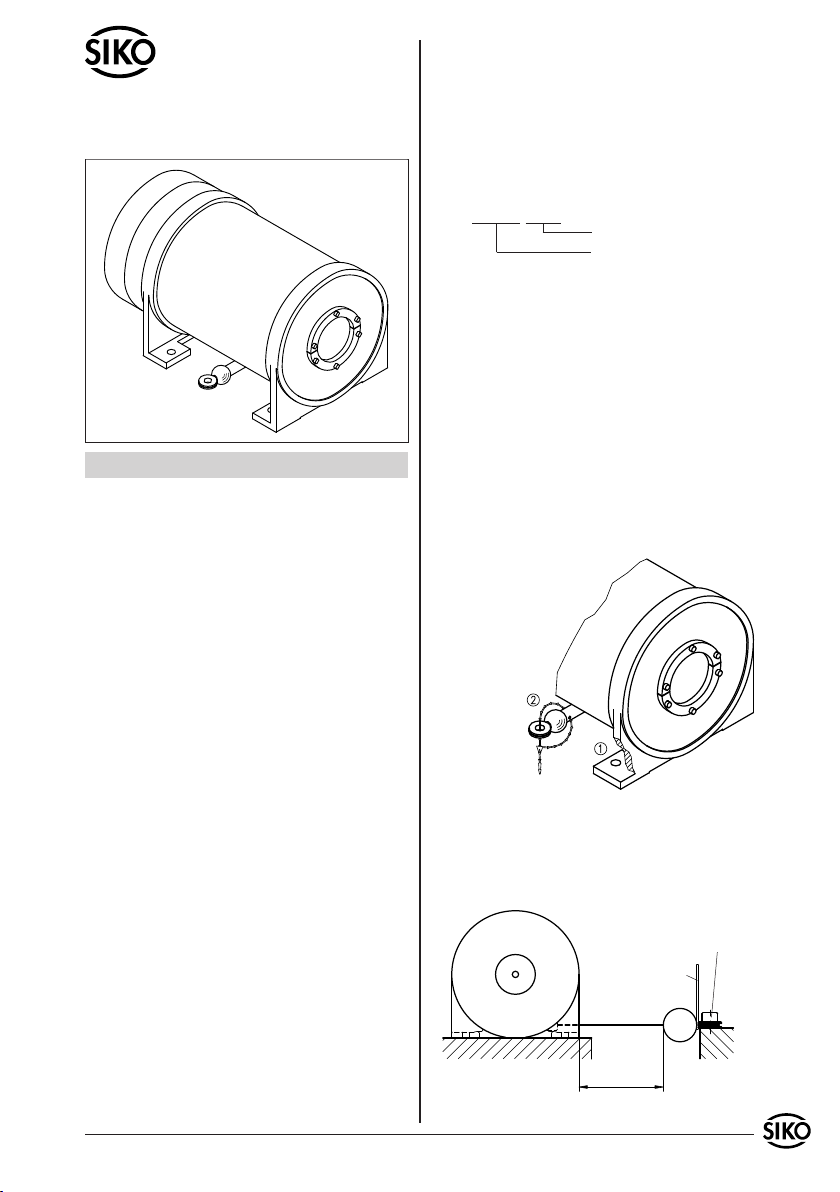
Fig. 1: Mounting
Fig. 2: Measuring range
Measuring range
max. extension length
sticker
screw M8
ENGLISH
1. Warranty information
In order to carry out installation correctly, we
strongly recommend this document is read very
carefully. This will ensure your own safety and
the operating reliability of the device.
Your device has been quality controlled, tested
and is ready for use. Please respect all warnings
and information which are marked either directly
on the device or in this document.
Warranty can only be claimed for components
supplied by SIKO GmbH. If the system are used
together with other products, there is no warranty
for tho complete system.
Repairs should be carried out only at our works.
If any information is missing or unclear, please
contact the SIKO sales staff.
2. Safety information
With the long wire length and the built-in spring
motor there is a risk of injury if the unit is handled
improperly or mounted incorrectly.
Avoid sudden release of the wire when exten-
ded!
Do not let the wire glide in your hand / through
your fingers for braking. This can lead to injuries
(eg. burns)!
Protect your working site before carrying out any
mounting / repair works!
Ensure the wire is visible to everybody to avoid
•
•
•
•
•
•
•
•
injuries and damages. Unauthorized personnel or
animals should not have access.
3. Identification
Please check the particular type of unit and type
number from the identification plate. Type number
and the corresponding version are indicated in the
delivery documentation.
eg. SGL135-0023
version number
type of unit
4. Installation
For mounting, the degree of protection specified
must be observed. It is determined by the moun-
ted transducer, but not higher than approx. IP40.
If necessary, protect the unit against environmen-
tal influences such as sprayed water, dust, knocks,
extreme temperatures.
The wire actuated transmitter is a high quality
measuring device and should be mounted to a flat
surface (fig. 1).
Use the 4 holes (for M8 size screws) for fixing to
the mounting surface (1).
Remove the transport safety cable tie (2).
•
•
User Information
SGL...
Wire Actuated
The wire end / wire has to be pulled out up to
the fixing point. For mounting try to reduce the
wire extension length to a minimum; this will
allow mounting without risk. Any torsion of the
wire is to be avoided.
•
4 SGL... Datum 21.11.2008 Art.Nr. 81383 Änd. Stand 369/08
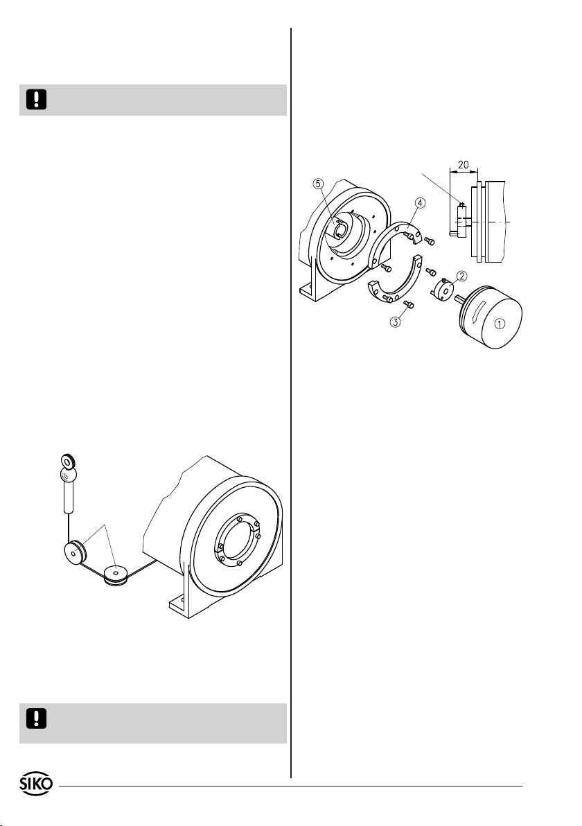
Fig. 3: Guide rollers
guide rollers
Fig. 4: Encoder mounting
Use screwdriver
DIN 911 SW1.5
SIKO GmbH
Werk / Factory:
Weihermattenweg 2
79256 Buchenbach-Unteribental
Postanschrift / Postal address:
Postfach 1106
79195 Kirchzarten
Telefon/Phone +49 7661 394-0
Telefax/Fax +49 7661 394-388
E-Mail info@siko.de
Internet www.siko.de
Service [email protected]e
Fix the wire end, eg. by using a screw M8 (fig. 2).
Before the first use of the system pull out the
wire three times at the length required later when
the unit is mounted on the machine.
Attention! Maximum extension length of the wire
must not be exceeded.
Wire handling
Make sure that the wire goes out horizontally; this
will avoid damage at the wire outlet and increase
the unit's lifetime.
Avoid sudden release of the wire when it is ex-
tended as this will lead to incorrect rewind and
entanglements with subsequent wire breakage.
The wire must always be under tension (by the
spring’s force).
The sticker on the wire end should be attached
visibly at the mounting place (fig. 2).
For correction function the wire must remain wit-
hout kinks or flattening.
Guide rollers (accessory eg. SIKO type UR)
Are used for applications where wire actuated
transducer and wire cannot be mounted in one
line. Using guide rollers the wire can be pulled out
in any direction (fig. 3).
Guide rollers must be mounted in line with the
wire.
Maintain cleanliness of guide rollers at all
times.
•
•
•
•
Check whether encoder’s (1) and carrier plate’s
(2) mounting dimensions fit.
Slide carrier plate (2) onto the encoder shaft (size
20) and use a grub screw for fixing.
Slide both encoder and carrier plate in one of the
slots of the bearing tube (5).
For mounting the encoder, equaly tighten the
screws (3) on the servo flanges. Mount without
force!
•
•
•
•
Guide rollers reduce the wire’s lifetime.
5. Transducer mounting
The wire actuated unit is ready to be fitted to an
incremental or absolute encoder (fig. 4).
The encoder’s break-away torque and operational
torque must not exceed the admissable value
of 3 Ncm.
Remove screws (3) and servo flanges (4). Behind
you will find a carrier plate (2).
•
•
•
Nominal drum circumference is 400mm. Optimiza-
tion of the measuring accuracy can be achieved by
programming (adapting) the follower electronics
accordingly or by using a programmable encoder. If
required, a measuring protocol can be provided for
new units. Assemblies should be checked regularly
(service intervals of approx. 1 year).
6. Adjustment
For adjusting the encoder, release screws (3) and
turn encoder (1) in arrow direction. Then retigh-
ten screws.
•
Table of contents
Languages:


