Streacom BC1 User manual

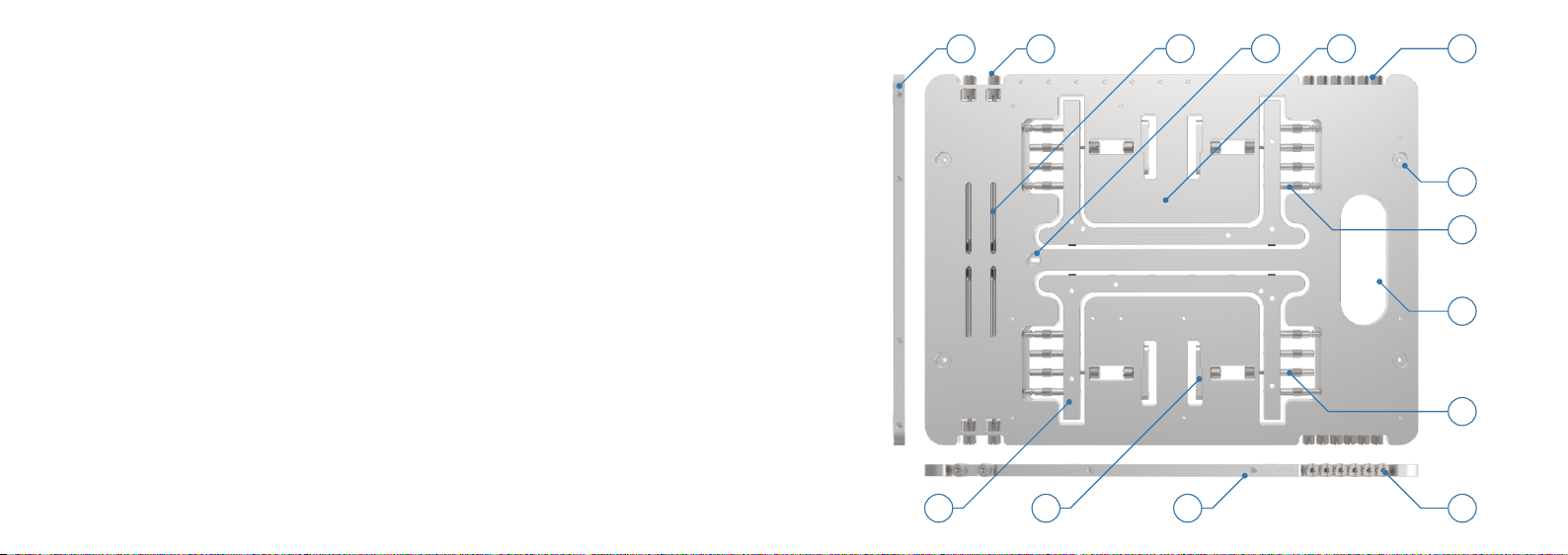
6 - 6#32 thumbscrews x 6
5 - Main body
8 - Pushpin standoff x 8
4 - Kensington lock
7 - Foot mounting hole x 4
13 - Bracket x 4
3 - Drive slots x 2
14 - Foot x 2
12 - Left/Right bracket mounting point x 4
9 - Integrated carry handle
11 - M3 thumbscrews x 6
BC1 Overview
2 - PCI thumbscrew & nut x 4
1 - Top/Bottom bracket mounting point x 8
10 - Threaded standoff x 8
BC1 Specification
Width - 260mm
Assembled height - 115mm
Weight - 1.82Kg
Length - 370mm PSU support - ATX 12V / BTX, ATX large and ATX-EPS
Thickness - 8mm
Table material - AL5052
Screw material - SS304
Drive support - Up to 2 x 2.5" or 2 x 3.5"
Motherboard support - XL, E, Mini, & Micro- ATX, Mini ITX
Max total load capacity - 25Kg
Motherboard standoff height - 25mm
Bracket cooling support - 240, 140, 120, 92, 80 mm
PSU max weight - 10Kg
Max bracket weight - 5Kg 8
6
7
14
2
9
10
1113
1
12
5
34
The difference between the M3 and 6#32 thumbscrew thread is subtle, so ensure the correct one is
used to avoid damage to your BC1. The M3 and 6#32 thumbscrews also feature an inner thread on the
head of the screw which allows M3 screws to be secured, giving additional stacked mounting options.
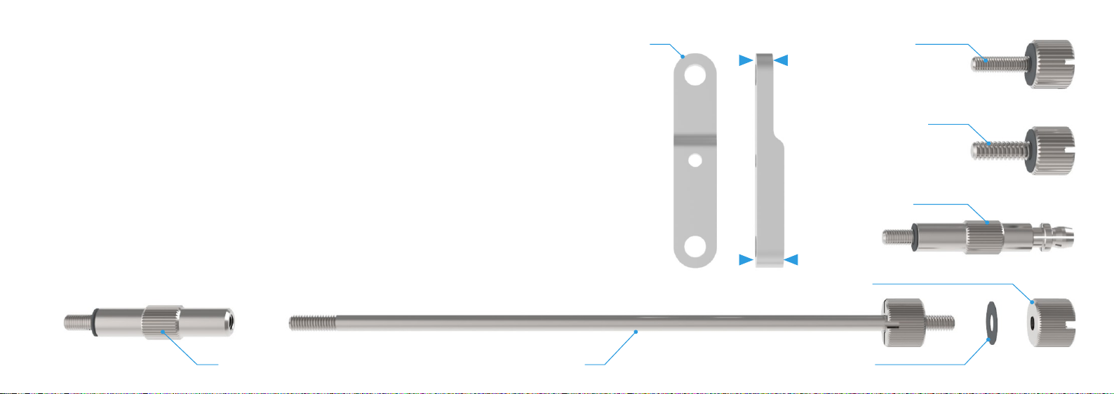
Introduction to the screws & brackets
The BC1 is supplied with 5 different types of screw which are used to mount all the various hardware to
the table. All screw threads are M3 except for the 6#32 thumbscrews which are used to attach 3.5" drives
and the PSU.
The BC1 brackets are used to fix additional components to the main body and feature a thick and thin side
which are interchangeable and designed to accommodate various screw lengths and thread depths,
depending on the hardware being fitted.
Note that all the screws feature a thin plastic washer at the base to ensure there is minimal damage to the
aluminium surface at the point of contact. The PCI thumbscrews are packed with extra washers which
should be used between the brackets and main body to minimise damage.
1M3 thumbscrew
Threaded standoff
6#32 thumbscrew
Pushpin standoff
Washer
PCI thumbscrew
Bracket
5mm
3mm
PCI nut
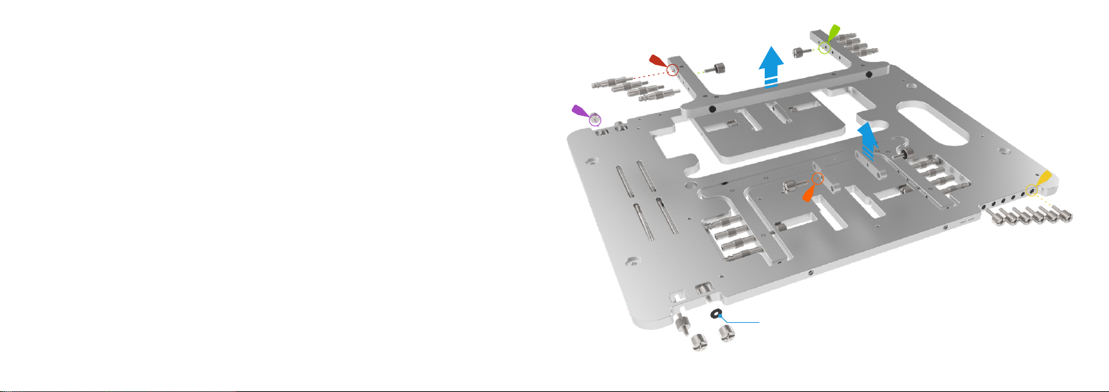
Removing feet, brackets and screws from the main body
The BC1 features a unique self contained design which means all the parts required for assembly
are stored and fitted directly to the main body. Before you can begin any assembly, the critical
parts (e.g. feet) and those that will be required by accessories (e.g. side brackets) should be
removed from the main body. This is done by simply removing the thumbscrews used to secure
each of the parts, or in the case of thumbscrews, simply unscrewing from the main body.
The feet are each held in place by 2 thumbscrews on either side. The same thumbscrews used
to secure the feet when stored will be used to attached the feet in the assembled position
although any of the M3 thumbscrews can be used as they are identical and interchangeable.
The pushpin and threaded standoffs are secured to the feet and can be removed at this point
depending on how many are required by the hardware being installed.
The PCI thumbscrews are removed by loosening or removing the nut at the top, then angling
the screw downwards and away from the table. It is recommend that you remove them in sets
of 2 on opposite sides, as the slots they occupy are used to mount drives.
2
Washer for use with brackets
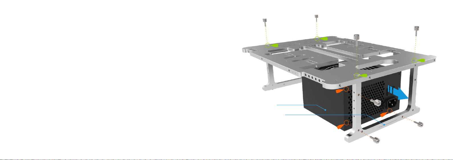
To install the feet, ensure the engraved line on the bottom of both feet is facing outwards, then
secure them to the main body using the M3 thumbscrews from the top and through the enlarged
circular holes.
Make sure the thumbscrews are properly tightened and if necessary use a screwdriver as this is
critical for a stable platform.
Fitting the feet and PSU
With the feet secured, it is now possible to fit the PSU which attaches directly to the right side foot
under the table. Only 3 thumbscrews are required, but it is important to check if your PSU
requires M3 or 6#32 threaded screws. The BC1 allows for both orientations of the PSU, so it
can be flipped if required, with the fan facing downward.
3
Engraved Line
ATX PSU

The BC1 supports 2 x 3.5" or 2 x 2.5" drives which mount
vertically to the underside of the main body using the 6#32 for
3.5" drives or M3 thumbscrews for 2.5" drives.
Fitting hard drives & standoffs to the main body
Note that threaded standoffs can also be used instead of
pushpin ones or in combination and require M3 screw in
order to lock the motherboard more securely for permanent
setups.
In preparation for fitting the motherboard and PCI cards,
standoffs must be fitted to the upper surface of the main body.
Depending on what size motherboard and how many cards
are being installed, use the correct number of standoffs in the
matching locations. The motherboard uses pushpin or
threaded standoffs whilst the PCI card supports require
threaded standoffs.
4
mITXmATXATX
PCI card
mounting holes
Motherboard
mounting holes
2.5" Drive
3.5" Drive
Pushpin or threaded standoff
Threaded standoff
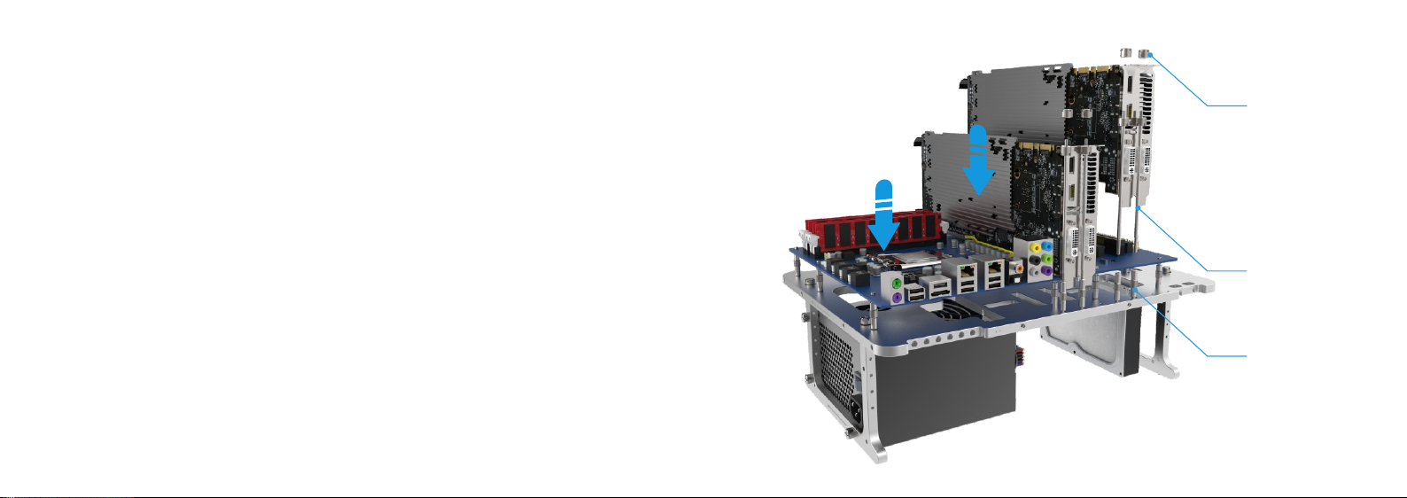
With the standoffs fitted to the main body and after verifying the correct support locations have
been installed, carefully lower the motherboard onto the pushpin standoffs and with a slight
amount of pressure, force them through the motherboard holes. This will securely lock the
motherboard in place. Note that any CPU retention plates should be fitted prior to installing the
motherboard for ease of use. If using threaded standoffs to secure the motherboard, install the
M3 screws to lock the motherboard in place.
A total of 4 PCI support screw sets are supplied, and can be used individually or in pairs for dual
width cards as required.
PCI cards are secured to the BC1 using the PCI thumbscrews which should first be screwed into
the threaded standoffs fitted to the PCI support mounting holes. The PCI card can then be
installed into the motherboard slot ensuring the card mounting bracket hole aligns with the top
of the PCI thumbscrew. Finally screw the PCI nut to the top of the PCI screw to lock the card in
place.
Fitting the motherboard and PCI cards
5
Threaded standoff
PCI thumbscrew
PCI nut
1
2
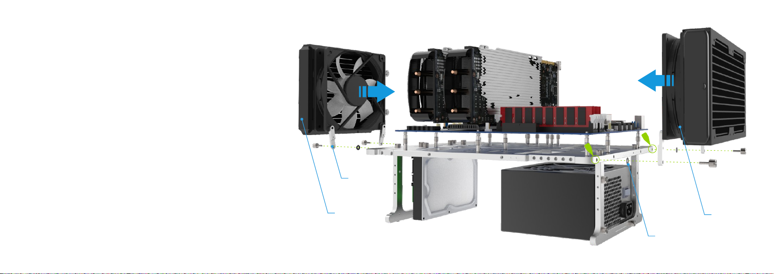
Using the side brackets
The washers supplied with the BC1 should be placed between the
bracket and table to avoid surface damage.
The hardware+bracket assembly can then be screwed to the side
of the table using the M3 thumbscrews. The mounting holes are
located along all 4 sides of the main body with brackets that are
designed to pivot in order to fit different hole spacings. These
include those used by 120mm, 140mm, and 240mm cooling fans.
The BC1 includes 4 side brackets which can be used for fixing
radiators, fans and virtually anything else that has a screw hole
mounting to the table. The brackets should first be fitted to the
hardware which you plan to mount using either screws that are
supplied with the hardware or the thumbscrews supplied with the
BC1. The bracket orientation is reversible, so choose between the
thick or thin side according to the length of the screw used to attach
the hardware.
6
240mm
Washer
140mm
Bracket

Cable routing is not shown, but this should be considered whilst planning the build and applied
accordingly.
To disassemble the BC1 simply reverse the procedure and when packing the screws and parts
ensure you replace them in the correct location, especially the M3 and 6#32 thumbscrews.
Most of these steps can be performed in any order and this guide is simply an overview of the
general procedure. It also demonstrates how parts can be used but as this is an open platform
designed for flexibility, there are multiple variations which are not shown.
When removing the motherboard make sure to pry it away carefully from the pushpin standoffs
to ensure no damage occurs.
Final notes
7
COPYRIGHT NOTICE
Copyright © 2018 All Rights Reserved. No part of this publication may be reproduced, stored in a
retrieval system, or transmitted, in any form or in any means – by electronic, mechanical,
photocopying, recording or otherwise – without prior written permission. All trademarks and
registered trademarks in this publication are the property of their respective owners.

Table of contents
Other Streacom Chassis manuals


Popular Chassis manuals by other brands

National Instruments
National Instruments PXI Express Series user manual

American Control Electronics
American Control Electronics MGB400 quick start guide

Cisco
Cisco CRS-1 - Carrier Routing System Router System description

ASROCK
ASROCK 1U12LX-14S Quick installation guide

Keysight Technologies
Keysight Technologies M9502A AXIe Firmware Revision Guide

AJA
AJA OG-X-FR Installation and operation guide


