Streak 800Pro User manual

STREAK 800Pro HEXACOPTER
Instruction Manual
1

Contents
1. Safety Notes........................................................................................................................................................3
2. Equipment Required For Assembly....................................................................................................................4
3. Che k List............................................................................................................................................................5
4.1 Assembly Steps - Flight dire tion indi ator......................................................................................................8
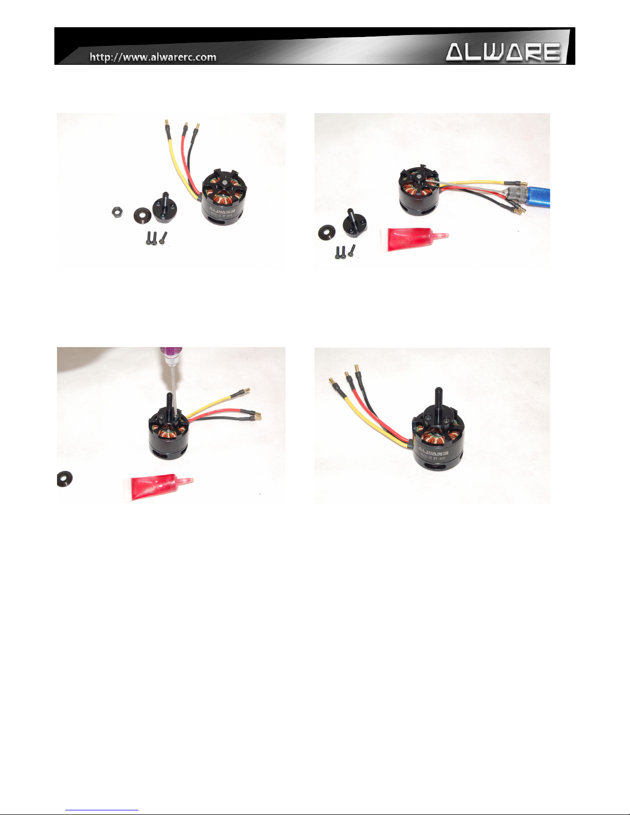
4.2 Assembly Steps – Motor....................................................................................................................................9
4.3 Assembly Steps – Motor Mount .....................................................................................................................10
4.4 Soldering Job...................................................................................................................................................11
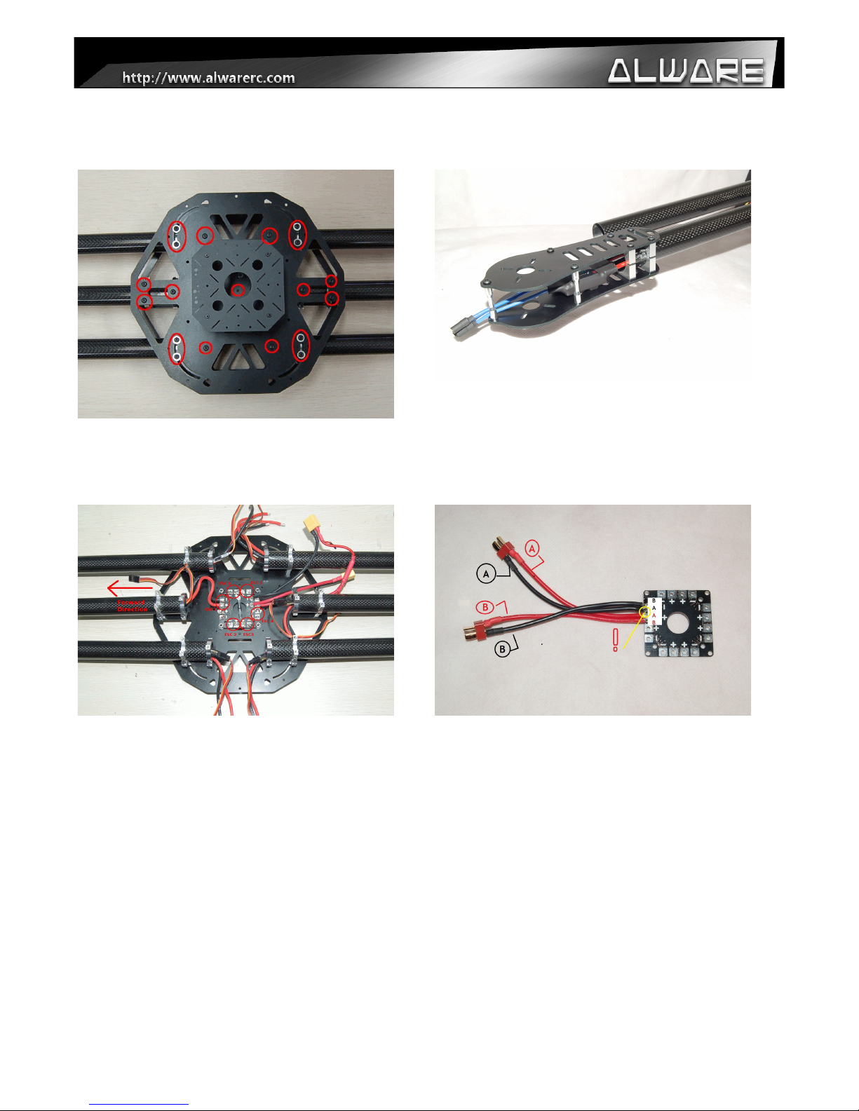
4.5 Assembly Steps – ESC and ESC board...........................................................................................................12
4.6 Assembly Steps – Motors & Propellers...........................................................................................................14
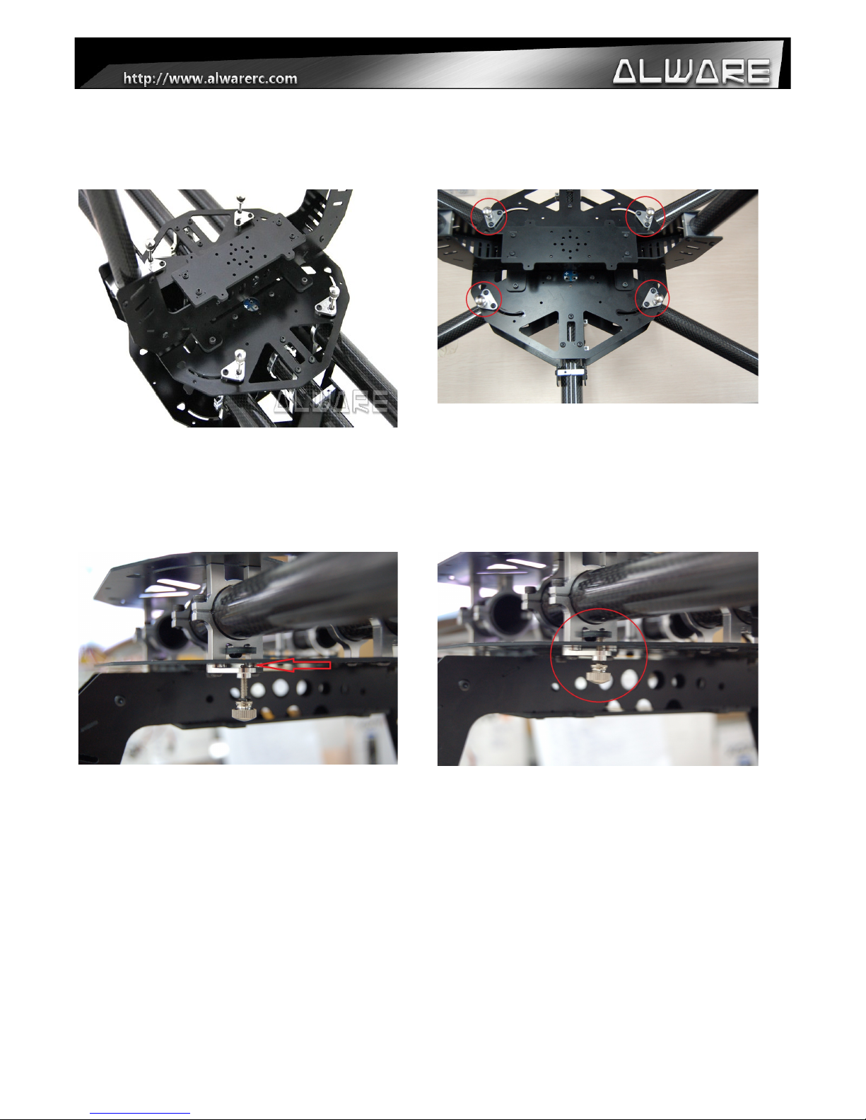
4.7 Assembly Steps – Bipod Landing Gear...........................................................................................................16
5. Qui k Collapsible Illustration...........................................................................................................................18
6. Gimbal Mounting..............................................................................................................................................20
7. Multi opter Controller Mounting Illustration...................................................................................................22
8. Spe ifi ation......................................................................................................................................................23
End Of Manual......................................................................................................................................................24
2

1. Safety Notes
Do fly only in safe areas and always away from other people! Do not operate RC aircraft within the
vicinity of homes or crowds of people. RC machine are prone to accidents, failures, and crashes due
to a variety of reasons including pilot error, radio interference, and lack of maintenance. Pilot are
responsible for their actions and damage or injury occuring during the operation of RC aircraft
machine.
hen flying the aicraft, the fast rotating props of Streak 800 may cause serious injuries with any
accident occurred. Therefore please keep in mind that safety at first during the flight.
The ONLY Flying direction suitable for Streak 800
Make sure you have installed your own Hexacopter Controller and the Props in the correct direction
according to the factory's manual of the Controller.
3

2. Equipment Required For Assembly
6pcs-- 40A ESC(6S
22.2V) (e.g. Hobby ing
FlyFun 40A ESC)
18pcs-- 3.5mm Bullet
Connector (Female) for
6pcs ESC
1pcs-- “+” Mode
Hexacopter Controller
(e.g. DJI K-M)
2pcs-- 6S LiPo Battery
3500-7500mAh 22.2V
( ill be connected in
Parallel)
2pair-- Connectors For
Batteries and Power
Board
1pcs-- Transmitter 1pcs-- Receiver 1pcs-- Lipo Charger &
the connector to fit the
Lipo Battery.
4

3. Check List
Please Check the Follow parts.
Alware Multicopter Brushless Motor
3515-15 KV400 (Not included unless otherwise
specified.) 6 Set
Screw set come with Motor.
6 Set
Apc Propeller 14x4.7SFP (C )
3 Pcs
Apc Propeller 14x4.7SFP (CC )
3 Pcs
Large Current Power/ESC Board (Black/
Blue color) with 2 pairs Battery Cable.
Servo Extension ire ( 15cm )
6 pcs
5

A G wire Black ( 33cm )
6 pcs
A G wire Red ( 33cm )
6 pcs
Frame parts.
Motor Mount
6 Pcs
Carbon Fiber Leading Gear Assembly
2 Pcs
Landing Gear Skid (420 mm)
2 Pcs
FPV & GPS Mounting Assembly 1Pcs (left)
Landing Gear Frame Assembly 1 Pcs (right)
6

Other parts
Spare Hex Cap Screw M2x6mm Spare Hex Cap Screw M3x8mm Spare Hex Cap Screw
M3x10mm
Spare Hex Cap Screw
M3x12mm
Spare Round Cap Screw 8pcs x Battery Support Damper
1pcs x Direction Indicating
Sticker
7

4.1 Assembly Steps - Flight direction indicator
Step 1.
Cut the Direction Indicating Sticker with a
width of around 100mm.
Step 2.
Tear the cover layer of the Sticker before
stick to the front Carbon Arm Boom.
Step 3.
Stick the Direction Indicating Sticker to the
Fixed Carbon Arm Boom as to indicate the
Forward Flying Direction.
Step 4.
Use three pieces of Adhesive Tape to secure
the Direction Indicating Sticker.
Step 5.
Prepare the FPV & GPS Mounting Assembly.
Step 6.
Insert the FPV & GPS Mounting Assembly
into the opposite boom of the Direction
Indicating Sticker.
8

4.2 Assembly Steps – Motor
Step 1.
You will received 6 motors in
ALS800-CB.
Step 2.
For new motors, Thread Lock must be
applied to the two M3 Set Screws which is
pre-inserted in the motor.
(This is a must for safety flying.)
Step 3.
Install the Porp Mount to the motor using
3pcs M3 Hex Cap Screw. (Apply little
amount of Thread Locker when assembly
metal to metal parts.)
Step 4.
Double check the prop mount which must be
installed to the motor securely.
9

4.3 Assembly Steps – Motor Mount
Step 1.
Loosen the two screws before insert the
motor mount to the Carbon Arm Boom.
Step 2.
Insert the Motor Mount to the carbon boom
and stop until the boom edge is around 5mm
to the Inner Motor Metal Mount surface.
Step 3.
Adjust the Motor Mount to parallel to the
Streak 800Pro body before tighten the
screws.
Step 4.
Secure the Motor Mount by tighten the
screws on the Metal Mount.
Repeat Step 1 to 4 to install other Motor Mounts to the Carbon Boom Arms.
10

4.4 Soldering Job
Solder 2 pairs Battery Cable to the Large Current
Power/ESC Board and connect the other end to
the Battery Connectors. (Red = +ve , Black = -ve)
Do not short circuit two polarities!!
1.) Solder Black and Red A G wires to the ESC.
2.)Solder 3pcs 3.5mm Bullet Connectors
(Female) to the ESC.
3.)Connect Servo Extension ire to the Signal
Connector of ESC and secure it using Adhesive
Tape.
11

4.5 Assembly Steps – ESC and ESC board.
Step 1.
Uninstall the Upper Main Frame of Streak
800Pro by loosing 18pcs M3 Screws as
shown above.
Step 2.
Insert the Battery Power Cable and Signal
ire of the ESC into the Carbon Boom Arm.
Same for all 6pcs ESCs.
Step 3.
Solder the Battery Power ires of the ESC
to the ESC Board. (Red wire = +ve , Black
wire = -ve)
Step 4.
Solder 2 pairs Battery Cable to the Large
Current Power/ESC Board and connect the
other end to the Battery Connectors. (Red =
+ve , Black = -ve) Do not short circuit two
polarities!!
12

Step 5.
Install the Upper Main Frame back to the
body. (Apply little amount of Thread Locker
when installing Screws to metal part.)
Step 6.
Insert the FPV & GPS Mounting Assembly
completely to touch the Upper Main Frame
and secure it by tighten the M3 Screw circled
above.
Step 7.
Prepare the Landing Gear Frame Assembly.
Step 8.
Install the Landing Gear Frame Assembly to
the Lower Main Frame of the body using four
M3x10 Hex Cap Screws. (Apply little amount
of Thread Locker when installing Screws to
metal part.)
13

4.6 Assembly Steps – Motors & Propellers.
Step 1.
Prepare 4pcs M3x8mm HexCap Screws with
4pcs 3mm ashers to install the motors to the
Motor Mounts.
Step 2.
Insert a M3x8mm Screw into a 3mm asher
then insert to the motor mount slot as to mount
the Motor to it. (Apply little amount of Thread
Locker when assembly metal to metal parts.)
Step 3.
Secure the motor to the motor mount with
4pcs screws and washers.
Step 4.
Insert the Motor ires into the slot of motor
mount and connect with motors.
14

Step 5.
Repeat Step 1 to 4 for other 5 motors. Test the
motor first without propellers as to ensure the
rotating direction is correct. Exchange any two
motor wires to the ESC as to reverse the
direction if needed.
Step 6.
After ensuring the motors are running in the
correct direction, prepare the APC Props and
Prop mounting screw and washer from the
motors.
Step 7.
Insert the Root Hole Adapter (with 6mm inner
diameter) to the bottom side of APC Prop.
Step 8.
Install the Propeller to the motors and secure it
with Prop mount Screw and asher. (Please
refer to your Multicopter Controller Manual to
install the CC & C Props in the correct
direction.)
15

4.7 Assembly Steps – Bipod Landing Gear.
Step 1.
Insert the Landing Gear Skid into the mounting
hole of Carbon Fiber Leading Gear Assembly.
(Tips: You can rotate the Landing Gear Skid
into the hole with less effort.)
Step 2.
Adjust the length of the Landing Gear Skid.
Each side of the Landing Gear Skid should be
about 195mm.
Step 3.
Secure Landing Gear Skid onto the Carbon
Fiber Leading Gear Assembly using the M3
Set Screw which is pre-installed on the
Landing Gear Skid Metal Mount.
Step 4.
Repeat Step 1-3 to complete another side of
Bipod Landing Gear Assembly. (Remarks: Two
set of Bipod Landing Gear Assemblies are not
exactly the same but is in symmetry direction.)
16

Step 5.
Correct two Bipod Landing Gear Assemblies.
Step 6.
Insert the Carbon Boom of Bipod Landing Gear
Assembly into the metal mount of Landing
Gear Frame Assembly with the depth of
approximately 5mm.
Step 7.
Adjust the Bipod Landing Gear Assembly to
make the Landing Gear Skid be parallel to the
Fixed Arm and secure the Landing Gear
Frame Assembly with the M3 Screw.
17

5. Quick Collapsible Illustration
ith the Quick Collapsible Design, you can
fold four arms of Streak 800 easily for easy
transportation and storage. However you
must follow the coming step by step to fold
the arms correctly, otherwise the Lock
System may damaged!
Step 1.
Four Arms of Streak 800Pro are locked with
four Thumb Screws with Split Lock ashers.
Step 2.
Loosen the Thumb Screw and make sure it
is not touching the Fiber Frames. Then the
Arm can be folded or opened.
Step 3.
Make sure the Arm is fully folded or opened,
and then tighten the Thumb Screw
completely. It should throught two layer of
fiber frames as shown above.
18

Step 4.
Always check the above Screws are not
loosen, but not tighten completely too,
otherwise the Arms will not be foldable. If
you found that it is getting loosen, secure it
with Thread Locker for secure flight. Adjust
the tightness of these screws for the
smoothness of folding the arms, loosen it a
little bit if your folding arms are too tight.
***Always check if the above four Screws are
secured tightened completely for secure
flight. If you found that it is getting loosen,
secure it with Thread Locker.
Step 5.
Same as Step 4., check the above eight
screws for secure flying.
19

6. Gimbal Mounting
Step 1.
Indicate the Multi-Gimbal Mount which is
installed with Landing Gear Frame
Assembly.
Step 2.
Mounting position for GAUI CRANE 3 and
CRANE 2 Gimbals.
Step 3.
Mounting positions for other Gimbals such
as STO S-903(3-axis) Gimbal, STO Camera
Mount Kit S-550 etc.
20
Table of contents
Popular Toy manuals by other brands

Topsoaring
Topsoaring Topthermal 3M EP Assembling manual

Trix
Trix Minitrix 66301 manual

DICKIE SPIELZEUG
DICKIE SPIELZEUG RC Power Quad operating instructions

Vmar
Vmar Challenger 40ARF Trainer Assembly and operation manual

Ravensburger
Ravensburger Gravitrax Magnetic Cannon manual

Eduard
Eduard Super Mystere B.2 quick start guide

Horizon Hobby
Horizon Hobby Ultra-Micro P-51D Mustang BNF instruction manual

Hasbro
Hasbro baby alive E3690 quick start guide

Fisher-Price
Fisher-Price GTJ59 quick start guide

IKEA
IKEA Lillabo 904.699.60 manual

ItsImagical
ItsImagical Fresh & Fun Rocket Row instructions

Zapf Creation
Zapf Creation Baby Annabell 703243 manual