StressTel T-MIKE ES User manual

T-MIKE ES
OPERATION
MANUAL
021-002-090


T-MIKE ES
OPERATION
MANUAL
Version 2.1
July 2005
Revision D
¤2005 GE Inspection Techonologies
50 Industrial Park Road
Lewistown, PA 17044
Phone (717) 242-0327 Fax (717) 242-2606
www.geinspectiontechnologies.com


Table of Contents
Important Notice............................................................................................................................................1
Thoeory of Operation.................................................................. ...................................................................5
Diagram of a System.................................................................. ...................................................................7
Specifications............................................................................. ...................................................................9
Initial Setup...................................................................................................................................................11
Operation......................................................................................................................................................15
T-Mike Programmable.....................................................................................................................................25
Helpful Hints on Operation...............................................................................................................................27
Maintenance and Troubleshooting............................................................................................................. ......29
Warranty and Service......................................................................................................................................31
Appendix A....................................................................................................................................................35
Appendix B.....................................................................................................................................................37


IMPORTANT NOTICE
The following information must be read and understood by any user of a GE Inspection Technologies ultrasonic thickness gauge.
Failure to follow these instructions can lead to errors in thickness measurements or other test results. Decisions based on erroneous results
can, in turn, lead to property damage, personal injury or death.
General Warnings
Proper use of ultrasonic test equipment requires three essential elements:
. Selection of the correct test equipment
. Knowledge of the specific “test application requirements”
. Training on the part of the instrument operator
This operating manual provides instruction in the basic set-up and operation of the GE Inspection Technologies thickness gauge. There are,
however, additional factors that affect the use of the ultrasonic test equipment. Specific information regarding these additional factors is
beyond the scope of this manual. The operator should refer to text books on the subject of ultrasonic testing for more detailed information.
Operator Training
Operators must receive adequate training before using ultrasonic test equipment. Operators must be trained in general ultrasonic testing
procedures and in the set-up and performance required by a particular test. Operators must understand:
. Sound wave propagation theory
. Effects of the velocity of the test material

.Behavior of the sound wave where two different materials
are in contact
.Areas covered by the sound beam
More specific information about operator training, qualification, certification and test specifications is available from various
technical societies, industry groups, and government agencies.
Testing Limitations
In ultrasonic testing, information is obtained only from within the limits of the sound beam. Operators must exercise great
caution in making inferences about the test material outside the limits of the sound beam. Testing large materials may make
inspection of the entire test piece impracticable or impossible. When a less-than-complete inspection is to be performed, the
operator must be shown the specific areas to inspect. Inferences about the condition of areas not inspected, based on data
from the evaluated areas, should only be attempted by personnel fully trained in applicable statistical and probability tech-
niques. In particular, materials subjects to corrosion or erosion, in which conditions can vary significantly in any given area,
should be evaluated only by fully trained and experience operators.
Sound beams reflect from the first interior surface encountered. Because of part geometry and overlapped flaws or overlapped
surface, thickness gauges may measure the distance to an internal flaw rather than to the back wall of the material. Operators
must take steps to ensure that the entire thickness of the test material is being examined.
Ultrasonic Thickness Measurement Critical Operating Procedure
The following operating procedures must be observed by all users of ultrasonic thickness gauges in order to minimize errors in
test results.

3. Effects of Temperature on Calibration
Variations in temperature change the sound velocity of materials and transducer delay lines and therefore, zero calibration. All
calibrations should be performed on-site and with test blocks at the same temperature as the test piece, in order to minimize
errors due to temperature variations.
1. Calibration of Sound Velocity
The principle of operation of an ultrasonic thickness gauge is that the instrument measures the time of flight of an ultrasonic
pulse through the test piece and multiplies this time by the velocity of sound in the material. Thickness measuring error is
minimized by ensuring that the sound velocity to which the instrument is calibrated is the sound velocity of the material being
tested. Actual sound velocity in materials often varies significantly from the values found in published tables. In all cases, best
results are obtained if the instrument is calibrated on a velocity reference block made from the same material as the test piece.
This reference block should be flat, smooth and as thick as the maximum thickness of the test piece.
Operator should also be aware that sound velocity may not be constant in the material being tested; heat treating, for example,
can cause significant changes in sound velocity. This must be considered when evaluating the accuracy of the thickness
provided by this instrument. Instruments should always be calibrated before testing, and the calibration should be checked after
testing, to minimize testing errors.
2. Probe Zero Procedure
The probe zero procedure must be performed as described in this manual. The zero reference block should be clean and in good
condition, without noticeable wear. Failure to properly perform the probe zero procedure will result in inaccurate thickness
readings.

4. Transducer Selection
The transducer used in testing must be in good condition without noticeable wear of the front surface. Badly worn transducers
will have a reduced effective measuring range. The specified range of the transducer must include the complete range of
thickness to be tested. The temperature of the material to be tested must be within then transducer’s temperature range.
5. Use of Couplants
Operators must be familiar with the use of ultrasonic couplants. Testing skills must be developed so that couplant is used and
applied consistently to minimize variations in couplant layer thickness and errors in test results. Calibration and actual testing
should be performed under similar coupling conditions, using a minimum of couplant and applying consistent pressure on the
transducer.
6. Doubling
Ultrasonic thickness gauges will, under certain conditions, display readings which are twice (or in some cases, three times) the
actual material thickness being measured. This effect, commonly known as “doubling,” can occur below the minimum specified
range of the transducer. If the transducer being used is worn, doubling is possible at thickness greater that the minimum
specified range.
When using a new transducer, any reading that is less than twice the minimum specified range of the transducer may be a
“doubled” reading. The thickness of the material being tested should be verified by the use of other methods. If the transducer
shows any sign of wear, doubling may occur at thickness greater than twice the minimum specific range. This thickness should
be determined by calibrating the instrument and transducer combination on reference blocks that represent the complete range
of possible thickness that may be encountered in testing. This is particularly important when the test piece is being ultrasoni-
cally measured for the first time or in any case where the history of thickness of the specimen in unknown.

Chapter I
Theory of Operation
A. ULTRASONIC WAVE
The T-Mike ES measures the thickness of a material by launching an ultrasonic wave into the material using an ultrasonic
transducer and calculating the time for the wave to pass through the material and reflect back to the transducer. The time is
multiplied by the previously determined velocity in the material and the thickness is then displayed on the readout in inches or
millimeters.
B. ZERO PROBE FUNCTION
Each transducer (probe) and the electronics varies in the amount of time to transmit the signal to be measured. This time must be
subtracted from the total transmission time. The time correction is accomplished automatically by performing a “PROBE”
recognition operation. The means to perform this simple task is resident on the T-Mike ES and will be explained in detail later.
C. SINGLE POINT VELOCITY CALIBRATION
Upon recognition of the probe a calibration of the velocity of the material to be measured must be done. Arepresentative piece of
the material to be measured should be used for the CAL operation. Through the CAL operation the T-Mike ES measures the
ultrasonic transit time, calculates the velocity of the material and implants the velocity calculation in the T-Mike ES memory for
future measurements. If the velocity of the material is already known then it may be entered using the keypad. Important: Since
this velocity constant is used to determine thickness for all measurement (until it is changed through another CAL or PROBE
function) the accuracy of the thickness measurement depends upon the constancy of the ultrasonic properties in the material being
measured.

In order to ensure accurate measurement both the transducer face and the material to be measured should be wiped
clean. A drop of couplant should then be applied to either the probe face or contact point on the material being
measured. Foreign matter between the probe and the material can distort or prevent readings.
To maximize measurement accuracy select a calibration piece that has the same shape and approximate thickness as
the work piece being measured. Re-calibrate the T-Mike ES when the temperature of the work piece changes 5oC or
more from the calibration piece.
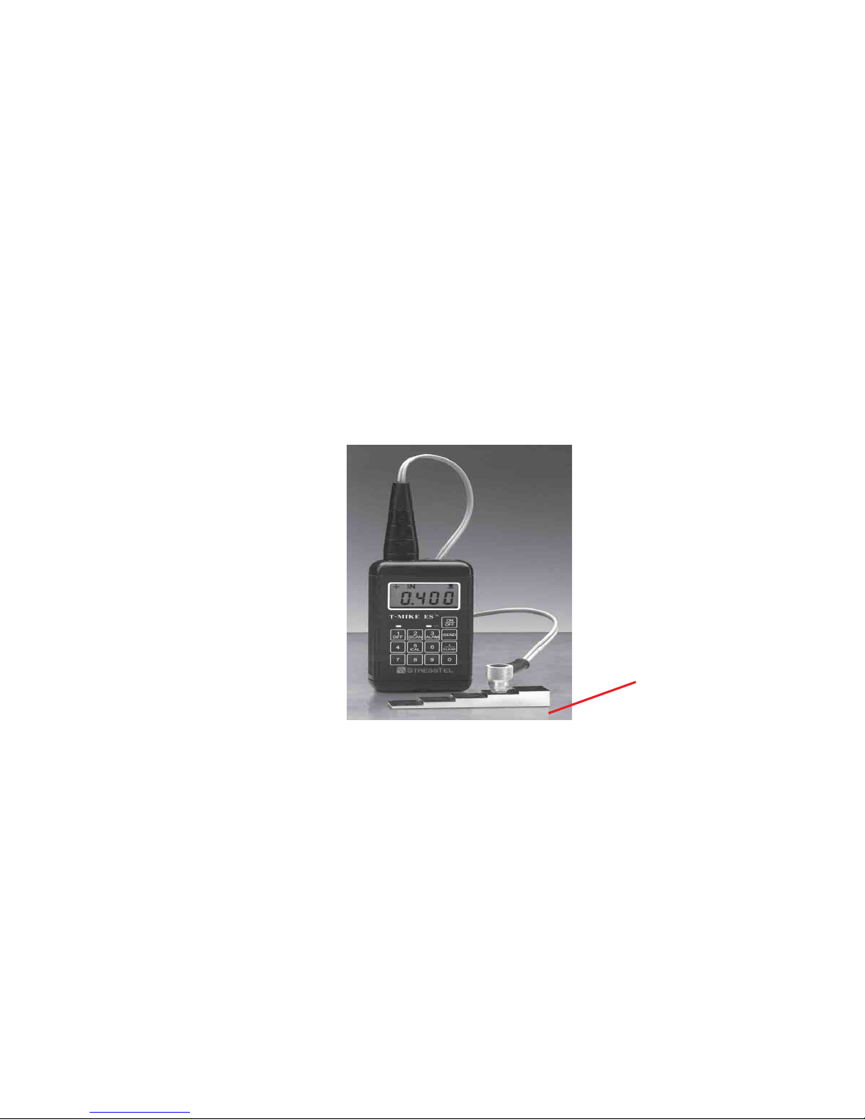
Chapter II
Diagram of a System
Probe
Step Block
Couplant
between Probe
and Test Block
T-MIKE ES

Chapter III
Specifications
T-MIKE ES
SPECIFICATIONS
APPROXIMATE MEASURING 0.040 - 19.999"
RANGE
RESOLUTION 0.001 in.
DISPLAY MEASUREMENT Backlit 4 1/2 digit
ALLOWABLE SURFACE
TEMPERATURE 0oF to 200oF
CABLE LENGTH 4 ft.
BATTERY POWER SUPPLY Alkaline
OPTIONAL BATTERY POWER Nicad
CONTINUOUS OPERATING 80 hours
TIME WITH BACKLIGHT
NORMAL OPERATING TIME 300 hours
WEIGHT 11 oz. with batteries
DIMENSION 2.5 x 4.5 x 1.25"


Chapter IV
Initial Setup
A. INTRODUCTION
For those settings that are seldom changed during operation of the T-Mike ES the INITIALSET UP procedure is designed to allow
the operator access to those settings without unnecessary complication of the unit’s normal operation.
These settings include:
Backlight on/off
Selection of Metric or English units of measure
Calibration Lock
Auto Send
The INITIAL SET UP procedure is accessed by holding the CAL key down and pressing the ON/OFF key.
When this is done the T-Mike ES will display the version code of the operating software contained in the unit until releasing the CAL
key. This information will be useful should the unit require service or updated software is desired.
Upon release of the CAL key the SETUP procedure continues as follows:

B. BACKLIGHT ON/OFF
The backlight setting can be selected by holding down the CAL key while turning on the unit. Release the CAL key at which time
the unit displays ON or OFF for the backlight. Press any key, except the 5/CAL key, to change backlight condition.
NOTE: It is recommended that the backlight be OFF when measurements are made in well-illuminated areas, as this will greatly
increase battery life.
C. METRIC/ENGLISH UNITS
Press and release the CAL key again.
The T-Mike ES will display the units in which it is set to measure thickness (IN or MM).
Press any key to select the desired unit of measurement.
D. CALIBRATION LOCK
Press the CAL key a third time.
The T-Mike ES will display the status of the calibration lock function (CAL or LOC).
When CALis displayed the velocity calibration function can be performed as described in Operation, Chapter V.
When LOC is displayed the calibration function is disabled. The velocity used in measurement cannot be changed without entering
this SETUP procedure again to change settings to CAL.
It is recommended that the lock feature be used when supervising personnel wish to prevent unauthorized change of the
calibrated velocity.

E. AUTO SEND
Press the CAL key a fourth time.
The T-Mike ES will display the status of the Auto Send (On/Off) function. Press any key except the 5/CAL key to
toggle On/Off.
Pressing the CAL key a final time completes the SETUP procedure and returns the T-Mike ES to the measurement
mode.


B. PROBE ZERO FUNCTION
The PROBE-ZERO function compensates the T-Mike ES for the fixed delay of the ultrasonic transducer. This function should be
performed at the start of each day (to compensate for transducer wear), or whenever the transducer is changed. Turn on the T-Mike
ES. Apply a drop of couplant to the end of the transducer. Place the transducer in steady contact with the probe disk located on
the top end of the T-Mike ES. TheT-Mike ES will automatically recognize that the probe is in contact with the disk, and will display
“Prb0” after it performs the zeroing function. The probe delay factor has now been calculated and entered into memory.
NOTE: During the PROBE-ZERO function, the T-Mike ES uses an internal velocity value to correctly measure the probe disk. Any
previous velocity entered by the operator will not change, and will be used in subsequent measurements.
The T-Mike ES also has the ability to perform a PROBE-ZERO on a user-supplied piece of material which must be 0.250 inches
thick and have a sound velocity of 233000 in/ms. In order for this
Chapter V
Operation
A. ON / OFF FUNCTION
The ON/OFF key is used to power on or off the T-Mike ES. When turned on, the unit will display a reading of zero. The PROBE-
ZERO function should be performed at this point, to compensate for any change in the transducer. After performing a PROBE-
ZERO, the T-Mike ES is ready to measure. The CALIBRATION function may also be activated at this point, to calibrate the T-Mike
ES to the sound-velocity of the material to be measured.
Table of contents
Other StressTel Measuring Instrument manuals


