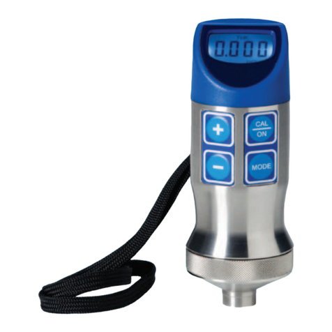
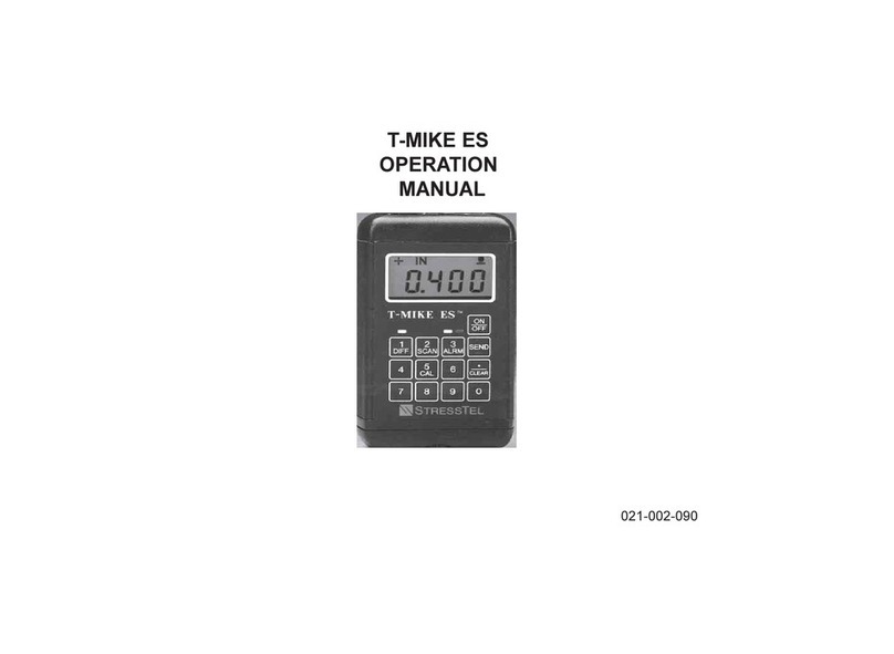
StressTel T-MIKE E User manual

T-MIKE E/P/B
OPERATION
MANUAL
T-MIKE E/P/B
OPERATION
MANUAL


2005 G E Inspection Technologies , LP
50 Industrial P ark R d.
Lewis town, PA 17044
US A
P : 717.242.0327, F : 717.242.2606
www.G E Ins pectionTechnologies.com
T -MIK E E /P /B
OP E R AT ION
MANUAL
R E V H
VERSION 4
2005 G E Inspection Technologies , LP
50 Industrial P ark R d.
Lewis town, PA 17044
US A
P : 717.242.0327, F : 717.242.2606
www.G E Ins pectionTechnologies.com
T -MIK E E /P /B
OP E R AT ION
MANUAL
R E V H
VERSION 4
021-002-147


Table of Contents
IMPORTANT NOTICE................................................................................................................. 1
THEORY OF OPERATION......................................................... ................................................. 5
DIAGRAM OF SYSTEM ............................................................................................................. 7
SPECIFICATIONS ...................................................................................................................... 9
INITIAL SETUP........................................................................................................................... 11
OPERATION .............................................................................................................................13
T-MIKE PROGRAMMABLE.................................................. .......................................................19
T-MIKE BASIC...........................................................................................................................21
HELPFUL HINTS ON OPERATION.............................................................................................23
MAINTENANCE AND TROUBLESHOOTING ................................................................................25
WARRANTY AND SERVICE....................................................................................................... 27
APPENDIX A............................................................................................................................29
APPENDIX B. .........................................................................................................................31


1
Important Notice
ThefollowinginformationmustbereadandunderstoodbyanyuserofaGEInspectionTechnologies ultrasonic
thicknessgauge.
Failure to follow these instructions can lead to errors in thickness measurements or other test results. Decisions
basedon erroneous results can, in turn, lead topropertydamage,personalinjuryordeath.
General Warnings
Properuseofultrasonictest equipment requires three essential elements:
· Selection of the correct test equipment
·Knowledgeofthespecific“testapplicationrequirements”
·Trainingonthepartoftheinstrumentoperator
Thisoperating manualprovidesinstructioninthebasicset-upand operationoftheGEInspectionTechnologiesthickness
gauge. Thereare,however,additionalfactors whichaffecttheuseofthe ultrasonictestequipment. Specificinformation
regarding these additional factors is beyond the scope of this manual. The operator should refer to text books on the
subjectofultrasonictestingformoredetailedinformation.
Operator Training
Operatorsmustreceive adequatetrainingbeforeusingultrasonic testequipment. Operatorsmustbe trainedingeneral
ultrasonictestingproceduresandintheset-upandperformancerequiredbyaparticulartest. Operatorsmustunderstand:
Soundwavepropagationtheory

2
•Effects of the sound velocity of the test material
•Behaviorofthesoundwave where two different materialsareincontact
•Areascoveredbythesoundbeam
More specific information about operator training, qualification, certification and test specifications is available from
varioustechnicalsocieties,industrygroups,andgovernment agencies.
Testing Limitations
In ultrasonic testing, information is obtained only from within the limits of the sound beam. Operators must exercise
great caution in making inferences about the test material outside the limits of the sound beam. For example, when
testinglargematerials,itmaybeimpossibleorimpracticaltoinspecttheentiretestpiece. When a less-than-complete
inspectionistobe performed, theoperatormustbeshown the specificareastoinspect. Inferencesabout the condition
ofareasnotinspected,basedon data from the evaluated areas, shouldonlybeattemptedbypersonnelfullytrained in
applicable statistical and probability techniques. In particular, materials subjects to corrosion or erosion, in which
conditionscanvarysignificantlyinany given area, should be evaluatedonlybyfullytrainedandexperienceoperators.
Sound beams reflect from the first interior surface encountered. Because of part geometry and overlapped flaws or
overlappedsurface,thicknessgaugesmaymeasurethe distance to an internal flaw rather than totheback wallofthe
material. Operators must take steps to ensure that the entire thickness of the test material is being examined.
UltrasonicThickness Measurement Critical Operating Procedure
Thefollowingoperatingproceduresmustbeobservedbyallusersofultrasonicthicknessgaugesinordertominimize
errors in test results.

3
Calibration of Sound Velocity
The principle of operation of an ultrasonic thickness gauge is that the instrument measures the time of flight of an
ultrasonic pulse through the test piece and multiplies this time by the velocity of sound in the material. Thickness
measuring error is minimized by ensuring that the sound velocity to which the instrument is calibrated is the sound
velocityofthematerialbeingtested. Actual sound velocity in materials oftenvary significantly from the values found in
published tables. In all cases, best results are obtained if the instrument is calibrated on a velocity reference block
made from the same material as the test piece; this block should be flat and smooth and as thick as the maximum
thickness of the test piece. Operator should also be aware that sound velocity may not be constant in the material
being tested; heat treating, for example, can cause significant changes in sound velocity. This must be considered
when evaluating the accuracy of the thickness provided by this instrument. Instruments should always be calibrated
before testing, and the calibration should be checked after testing, to minimize testing errors.
Probe Zero Procedure
Theprobezeroproceduremustbe performed as described in this manual. The zero reference block should be clean
and in good condition, without noticeable wear. Failure to properly perform the probe zero procedure will result in
inaccuratethicknessreadings.
Effects of Temperature on Calibration
Variationsintemperaturechangethesoundvelocityofmaterialsandtransducerdelaylinesandtherefore,zerocalibration.
Allcalibrationsshouldbeperformedon-siteandwithtestblocksatthesametemperatureasthetestpiece,inorderto
minimizeerrorsduetotemperature variations.
Transducer Selection
The transducer used in testing must be in good condition without noticeable wear of the front surface. Badly worn
transducers will have a reduced effective measuring range. The specified range of the transducer must include the
completerangeof thickness tobetested. Thetemperature of thematerialtobe testedmustbewithinthen transducer’s
temperaturerange.

4
Use of Couplants
Operators must be familiar with the use of ultrasonic couplants. Testing skills must be developed so that couplant is
used and applied in a consistent manner to minimize variations in couplant layer thickness and errors in test results.
Calibrationandactualtestingshouldbeperformedundersimilarcouplingconditions,usingaminimumofcouplant
andapplyingconsistentpressureonthetransducer.
Doubling
Ultrasonic thickness gauges will, under certain conditions, display readings which are twice (or in some cases, three
times) the actual material thickness being measured. This effect, commonly known as “doubling,” can occur below
the minimum specified range of the transducer. If the transducer being used is worn, doubling is possible at
thicknessesgreater that the minimum specified range.
When using a new transducer, any reading which is less than twice the minimum specified range of the transducer
may be a “doubled” reading, and the thicknesses of the material being tested should be verified by the use of other
methods. If the transducer shows any sign of wear, doubling may occur at thicknesses greater than twice the
minimumspecificrange. Thisthickness should be determined by calibrating the instrument/transducer combination
on reference blocks that represent the complete range of possible thicknesses that may be encountered in testing.
This is particularly important when the test piece is being ultrasonically measured for the first time or in any case
where the history of thickness of the specimen in unknown.

5
Chapter I
Theory of Operation
A. Ultrasonic Wave
TheT-MikeEmeasuresthethicknessofamaterialbylaunchinganultrasonic wave into the material using an
ultrasonictransducerandcalculatingthetime for the wave to passthroughthematerialandreflectbackto the
transducer. The time is multiplied by the previously determined velocity in the material and the thickness is
then displayed on the readout in inches or millimeters.
B. Zero Probe Function
Eachtransducer(probe) and theelectronicsvariesinthe amountoftimetotransmit the signaltobemeasured.
Thistime mustbesubtractedfromthetotaltransmission time. Thetimecorrectionisaccomplishedautomatically
by performing a “PROBE” recognition operation. The means to perform this simple task is resident on theT-
Mike E and will be explained in detail later.
C. Single Point Velocity Calibration
Upon recognition of the probe a calibration of the velocity of the material to be measured must be done. A
representativepieceofthematerialtobe measured should be used for the CAL operation. Through the CAL
operationtheT-MikeEmeasures the ultrasonictransittime,calculatesthe velocityofthematerialand implants
the velocity calculation in the T-Mike E’s memory for future measurements. If the velocity of the material is
already known then it may be entered using the keypad. Important: Since this velocity constant is used to
determine thickness for all measurement (until it is changed through another CAL or PROBE function) the
accuracy of the thickness measurement depends upon the constancy of the ultrasonic properties in the
materialbeingmeasured.

6
Inordertoensure accurate measurementboththetransducerfaceand the materialtobemeasuredshould be
wipedclean. Adropofcouplant should then beappliedtoeithertheprobe face or contactpoint on the material
beingmeasured. Foreignmatterbetweentheprobeandthematerialcandistortorpreventreadings.
To maximize measurement accuracy select a calibration piece that has the same shape and approximate
thickness as the work piece being measured. Re-calibrate the T-Mike E when the temperature of the work
piecechanges5oCormorefromthecalibrationpiece.

7
PROBE
T-MIKE E
COUPLANT USED
BETWEEN THE
PROBE AND BLOCK
BLOCK
Chapter II
Diagram of a System

8
Chapter III
Specifications
T-MIKE E/P/BSPECIFICATIONS
Approximate Measuring range 0.040-19.999”
(Material and Application Dependent)
Resolution 0.001in. Display Measurement Backlit 4 ½ digitAl-
lowable Surface Temperature 0oF to 200oF
Cable Length 4 ft.
Battery Power Supply Alkaline
Optional Batter Power Nicad
Continuous Operating Time with Backlight80hours
Normal Operating Time 300hours
Weight 11 oz.
Dimension 2.5 x 4.5 x 1.25”

9
Chapter IV
Initial Setup
A. Introduction
For those settings which are seldom changed during operation of the T-Mike E the INITIAL SET UP
procedureisdesignedtoallowtheoperator
access to those settings without unnecessary complication of the units normal operation.
Thesesettingsinclude:
Backlight on/off
Selection of Metric or English units of measure
CalibrationLock
TheINITIALSETUPprocedureisaccessedbyholdingtheCALkey down andpressingtheON/OFFkey.
Whenthisisdone theT-Mike E willdisplaytheversioncodeof the operating softwarecontainedin the unit
until the CAL key is released. This information will be useful should the unit require service or updated
softwareisdesired.
Uponreleaseof the CAL key the SETUP procedure continues as follows:
B. Backlight On/Off
When the CAL key is first released the T-Mike E will display the words ON or OFF to indicate the status of the
backlight. The backlight setting can be selected by pressing the UP or DOWN arrow key.

10
NOTE: Itisrecommencedthat the backlight beOFFwhenmeasurementsaremade in well-illuminated areas,
as this will greatly increase battery life.
C. Metric/English Units
Press the CAL key a second time.
The T-Mike E will display the units in which it is set to measure thickness (IN or MM).
Press the UP or DOWN arrow keys to select the desired unit of measurement.
D. CALIBRATION LOCK
Press the CAL key a third time.
The T-Mike E will display the status of the calibration lock function (CAL or LOC).
WhenCALisdisplayedthevelocity calibrationfunctioncan beperformedasdescribed inChapterV,Operation.
When LOC is displayed the calibration function is disabled. The velocity used in measurement cannot be
changed without entering this SETUP procedure again to change settings to CAL.
It is recommended that the lock feature be used when supervising personnel wish to prevent unauthorized
changeofthecalibratedvelocity.
Pressingthe CALkeyafinaltimecompletestheSETUPprocedureandreturnstheT-Mike Etothemeasurement
mode.

11
Chapter V
Operation
A. ON / OFF Function
Press this key to turn the T-Mike E on. The
unit will display a reading of zero. The T-Mike E is now ready for measurement or calibration. In order to
compensateforanychangeintheultrasonictransducer,aPROBEZERO function should be performed at
this point.
B. Probe Zero Function
ThePROBEZEROfunctioncompensates theT-Mike E for the fixed delay of the ultrasonic transducer.
Thisfunctionshouldbeperformedatthe start of each day (to compensate for transducer wear) or when-
ever the transducer is changed. Apply a drop of couplant to the end of the transducer. Press the ON/OFF
button on the keyboard to turn on the T-Mike E.
Place the transducer in steady contact with the probe disk located on the top of theT-Mike E. DO NOT
use another 0.250 test piece since the velocity of the probe disk is carefully controlled and errors will
result.
The T-Mike E recognizes that the probe is in contact with the probe disk, and automatically performs the
PROBE ZERO function. Upon completion of the function Prb 0 will appear on the display indicating that the
appropriatetransducerdelayfactorhasbeen entered in memory.
ON
OFF

12
NOTE: During the PROBE function, the T-Mike E velocity is temporarily reset to the velocity of the probe
disk(0.2330 in./msec.). Upon completion of the PROBE function the velocity will return to the last calibrated value.
This allows the operator to continue measurements on the previously calibrated material.
C. Material Calibration to Known Thickness
The following procedure is used to calibrate the T-Mike E sound velocity to a known sample of material. Some
materials may exhibit sound velocity variations which can cause errors in measurement. Be sure to check a
representative group of samples to determine if such variation is present.
First follow the above PROBE ZERO procedure to calibrate the delay of the ultrasonic transducer being used.
Apply a drop of couplant to the representative piece of material of known thickness. This piece is called the
sample.
Place the probe in steady contact with the surface of the sample. The T-Mike E will display a thickness reading
using the last calibrated velocity.
Press the CAL key to lock in the reading. The transducer may now be removed from the sample. The
display on the T-Mike E will momentarily display CAL. Small arrows will appear in the upper left portion of the
display above the thickness readings. This indicates that the T-Mike E is in the calibration mode and enables the
UP/DOWN arrow keys.
Adjust the thickness shown on the T-Mike E display by using the UP and DOWN arrows. Note that when
these keys are held continuously, the speed at which the thickness changes will increase, making it easy to make
the large adjustments for materials such as plastic and aluminum.

13
When the correct thickness appears on the display,
press the CALkey again to display the sound velocity of the calibrated material as calculated by the T-
Mike E. The display of sound velocity will be indicated by the appearance of appropriate velocity units
(IN/ms or M/S) above the displayed velocity value. Press the CAL key one final time to accept this
soundvelocityandreturntothemeasurementmode.
Check the calibration by replacing the probe on the sample piece. The T-Mike E should display the
corrected thickness of the sample.
NOTE: When the T-Mike E is in the CALIBRATION mode the unit will not make further measurement
untilthecalibrationprocedureiscompleted.
D. Calibration From Known Velocity
Thefollowing procedure is used to calibrate theT-Mike E to a givenmaterialvelocity.
FollowtheabovePROBEproceduretocalibratethedelayoftheultrasonictransducerbeingused.
Press the CALkey. The arrow symbols will appear in the upper left portion of the display
indicatingtheUP/DOWNarrowkeysareactive.
Press the CAL key a second time. The display on the T-Mike E will display the current velocity
andtheappropriateunitsofmeasure.
CAL

14
UP
DOWN
Or if metric units are selected:
Use the UP and DOWN arrow keys to scroll the velocity to the known velocity of the material.
Note that when these keys are held continuously, the speed that the velocity changes will increase, making
it easy to make the large adjustments for materials such as plastic and aluminum.
When the desired velocity appears on the display, press the CALkey again to enter that
velocity for use in thickness measurements and to return to the measurement mode.
E. Thickness Measurement
Removedirt,loosematerial,andcouplantresiduefromthesurfaceofmaterialatpointswhere
measurementsare desired. Verify that the PROBE and CALfunctions have been performed.
Place a drop of couplant on the material surface at the measurement point.
Place the transducer in steady contact with the surface of the material at the measurement point.
When a detectable echo is received from the back surface of the material, the echo indicator in the
upper right of the display will indicate the detection of an echo by changing in appearance to
representcontactbetweenthepicturedtransducerandthesamplesurface.
CAL
This manual suits for next models
2
Table of contents
Other StressTel Measuring Instrument manuals
Popular Measuring Instrument manuals by other brands
LaserLiner
LaserLiner DistanceCheck manual
Nidec-Shimpo
Nidec-Shimpo FG-3000R Operation manual
Compressed Air Alliance
Compressed Air Alliance FLP10000 Series user manual
Fluidwell
Fluidwell F010-U manual
Anritsu
Anritsu VectorStar ME7838 4 Series Maintenance manual
Keysight Technologies
Keysight Technologies U1701B quick start guide
