manuals.online logo
Brands
  1. Home
  2. •
  3. Brands
  4. •
  5. Siemens
  6. •
  7. Measuring Instrument
  8. •
  9. Siemens Class 87 Manual

Siemens Class 87 Manual

This manual suits for next models

1

Other Siemens Measuring Instrument manuals

Siemens SITRANS FUP1010 User manual

Siemens

Siemens SITRANS FUP1010 User manual

Siemens SMART 7KT User manual

Siemens

Siemens SMART 7KT User manual

Siemens SITRANS F C MASSFLO MASS 2100 User manual

Siemens

Siemens SITRANS F C MASSFLO MASS 2100 User manual

Siemens SIPROCESS GA700 User manual

Siemens

Siemens SIPROCESS GA700 User manual

Siemens SINUMERIK 840D sl Owner's manual

Siemens

Siemens SINUMERIK 840D sl Owner's manual

Siemens BETA 5SV8 001-6KK Service manual

Siemens

Siemens BETA 5SV8 001-6KK Service manual

Siemens SICAM MMU User manual

Siemens

Siemens SICAM MMU User manual

Siemens Sitrans F Series Administrator guide

Siemens

Siemens Sitrans F Series Administrator guide

Siemens SITRANS F FS200 Utility Owner's manual

Siemens

Siemens SITRANS F FS200 Utility Owner's manual

Siemens SITRANS F M MAG 5000 User manual

Siemens

Siemens SITRANS F M MAG 5000 User manual

Siemens SITRANS FUH1010 Specification sheet

Siemens

Siemens SITRANS FUH1010 Specification sheet

Siemens CALOMAT 6 User manual

Siemens

Siemens CALOMAT 6 User manual

Siemens SENTRON PAC3120 User manual

Siemens

Siemens SENTRON PAC3120 User manual

Siemens 7KG85 Series User manual

Siemens

Siemens 7KG85 Series User manual

Siemens 3NP19-1GB Series User manual

Siemens

Siemens 3NP19-1GB Series User manual

Siemens 7ME30 User manual

Siemens

Siemens 7ME30 User manual

Siemens SITRANS F User manual

Siemens

Siemens SITRANS F User manual

Siemens FIDAMAT 6-G User manual

Siemens

Siemens FIDAMAT 6-G User manual

Siemens SMART 7KT User manual

Siemens

Siemens SMART 7KT User manual

Siemens SENTRON 7KT PAC1200 User manual

Siemens

Siemens SENTRON 7KT PAC1200 User manual

Siemens VDO E-Tacho 1323.01 User manual

Siemens

Siemens VDO E-Tacho 1323.01 User manual

Siemens 5SV8001-6KK User manual

Siemens

Siemens 5SV8001-6KK User manual

Siemens US2:9810T24V User manual

Siemens

Siemens US2:9810T24V User manual

Siemens multiranger 100 Instruction manual

Siemens

Siemens multiranger 100 Instruction manual

Popular Measuring Instrument manuals by other brands

Powerfix Profi 278296 Operation and safety notes

Powerfix Profi

Powerfix Profi 278296 Operation and safety notes

Test Equipment Depot GVT-427B user manual

Test Equipment Depot

Test Equipment Depot GVT-427B user manual

Fieldpiece ACH Operator's manual

Fieldpiece

Fieldpiece ACH Operator's manual

FLYSURFER VIRON3 user manual

FLYSURFER

FLYSURFER VIRON3 user manual

GMW TG uni 1 operating manual

GMW

GMW TG uni 1 operating manual

Downeaster Wind & Weather Medallion Series instruction manual

Downeaster

Downeaster Wind & Weather Medallion Series instruction manual

Hanna Instruments HI96725C instruction manual

Hanna Instruments

Hanna Instruments HI96725C instruction manual

Nokeval KMR260 quick guide

Nokeval

Nokeval KMR260 quick guide

HOKUYO AUTOMATIC UBG-05LN instruction manual

HOKUYO AUTOMATIC

HOKUYO AUTOMATIC UBG-05LN instruction manual

Fluke 96000 Series Operator's manual

Fluke

Fluke 96000 Series Operator's manual

Test Products International SP565 user manual

Test Products International

Test Products International SP565 user manual

General Sleep Zmachine Insight+ DT-200 Service manual

General Sleep

General Sleep Zmachine Insight+ DT-200 Service manual

Sensa Core Lacto Spark user manual

Sensa Core

Sensa Core Lacto Spark user manual

VOLTCRAFT UTS-1980 operating instructions

VOLTCRAFT

VOLTCRAFT UTS-1980 operating instructions

EBCHQ 94915 Operation manual

EBCHQ

EBCHQ 94915 Operation manual

Balluff BIP LD2-T017-01-EP-S4 Series user guide

Balluff

Balluff BIP LD2-T017-01-EP-S4 Series user guide

Pulsar IMP Lite Series instruction manual

Pulsar

Pulsar IMP Lite Series instruction manual

ETCR 6800 user manual

ETCR

ETCR 6800 user manual

manuals.online logo
manuals.online logoBrands
  • About & Mission
  • Contact us
  • Privacy Policy
  • Terms and Conditions

Copyright 2025 Manuals.Online. All Rights Reserved.

E87010-A0095-T003-A4-87DU
Siemens Industry, Inc. 3617 Parkway Ln., Peachtree Corners, GA 30092
Description of Class 87 Pump Panels
Class 87 pump control panels include a Class 14 NEMA rated
contactor, a solid-state overload relay, either a circuit breaker
or fusible disconnect switch, a START push button, a HAND-
STOP-AUTO selector switch, a ground bar and external overload
reset button as standard. These components are mounted in a
NEMA 3R weather resistant enclosure with a gasketed door that
can be easily removed. Sizes 1 through 4 are furnished with
conduit knockouts on the bottom as well as pole mounting
brackets. Size 5 is furnished with mounting legs and size 6 is
base mounted. Factory installed and field accessories
are available.
IMPORTANT
THESE INSTRUCTIONS DO NOT PURPORT TO COVER ALL DETAILS OR
VARIATIONS IN EQUIPMENT, NOR TO PROVIDE FOR EVERY POSSIBLE
CONTINGENCY TO BE MET IN CONNECTION WITH INSTALLATION,
OPERATION OR MAINTENANCE. SHOULD FURTHER INFORMATION BE
DESIRED OR SHOULD PARTICULAR PROBLEMS ARISE WHICH ARE NOT
COVERED SUFFICIENTLY FOR THE PURCHASER’S PURPOSES. THE MATTER
SHOULD BE REFERRED TO THE LOCAL SIEMENS SALES OFFICE.
THE CONTENTS OF THIS INSTRUCTION MANUAL SHALL NOT BECOME PART
OF OR MODIFY ANY PRIOR OR EXISTING AGREEMENT, COMMITMENT OR
RELATIONSHIP THE SALES CONTRACT CONTAINS THE ENTIRE OBLIGATION
OF SIEMENS. THE WARRANTY CONTAINED IN THE CONTRACT BETWEEN
THE PARTIES IS THE SOLE WARRANTY OF SIEMENS. ANY STATEMENTS
CONTAINED HEREIN DO NOT CREATE NEW WARRANTIES OR MODIFY THE
EXISTING WARRANTY.
Class 87 3RE48
Description of Class 3RE48 Pump Panels
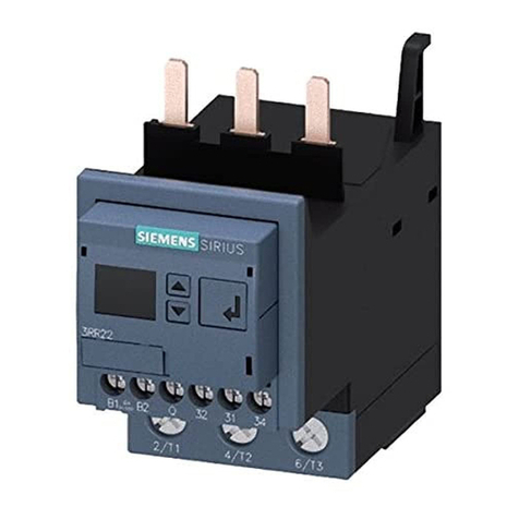
3RE48 pump control panels include a 3RT Innovations NEMA
rated magnetic contactor, a solid-state overload relay, either a
circuit breaker or fusible disconnect switch, a START push button,
a HAND-STOP-AUTO selector switch, a ground bar and external
overload reset button as standard. These components are
mounted in a NEMA 3R weather resistant enclosure with a
gasketed door that can be easily removed. Sizes 1 through 4
are furnished with conduit knockouts on the bottom as well as
pole mounting brackets. Field accessories are available.
A5E31166437A-004
Operation and Maintenance Instructions
for Class 87 and 3RE48 Pump Panels
Instructions
January, 2022
Supersedes Issue of
November, 2020
E87010-A0095-T003-A4-87DU
Siemens Industry, Inc. 3617 Parkway Ln., Peachtree Corners, GA 30092
Installation (Figure 1)
1. Remove the enclosure cover from the case.
2. Remove the knockout in the cover.
3. Mount pilot device support bracket assembly with two
mounting screws in location A (Size 1) or B (Size 2 and 3),
tighten screws to 25 lb.-in.
4. For pushbutton 3-wire control, make electrical connections
per Figure 2.
5. For the 2 and 3 position selector switches, make electrical
connections as shown in Figures 3, 4, 5, and 6.
6. Location of auxiliary interlocks may differ from diagrams,
therefore, markings on units should be followed.
7. Affix the appropriate legend label onto the cover next to the
pilot device.
Important! Prior to performing steps 1 through 13 verify that
all power is turned off to the pump control panel.
1. Examine each device on the panel for shipping damage and if
any is noted, notify carrier for claim. Do not apply power to
any damaged device.
2. Operate disconnect switch or circuit breaker with external
handle to verify operation.
3. Manually operate magnetic starter contactor to determine that
moving parts do not bind. Manual operation of the contactor
is performed by pressing on the movable contact assembly as
shown in Figure 1 for Class 87 and Figure 2 for 3RE48.
4. Verify that the supply voltage matches the voltage rating of the
pump panel.
5. Verify that the horsepower rating of the motor does not exceed
the horsepower rating of the pump control panel and the current
rating of the motor is within the adjustable range of the overload
relay. Set the FLA dial on the overload relay to the motor FLA.
Make sure the DIP switches are set to trip class 10 for pumping
applications. Refer to the overload elay instruction sheet
for details.
6. Install in conformance with National Electric Code – NFPA70
in the US or Canadian Electrical Code – CSA C22.1 in Canada,
and any applicable local electric codes.
7. Install the proper size dual element fuses in the disconnect
switch. The disconnect switch and fuse load block will accept
Class H, K, J or R fuses depending on the fuse holder. If the
available fault current of the supply is greater than 10kA, Class
R or J fuses must be used. Verify the available fault current of
supply does not exceed the interrupting rating of the fuses in
stalled and does not exceed the short circuit rating of the
pump panel controller.
8. If the pump controller includes an instantaneous trip breaker,
adjust the trip setting of the breaker according to the instruction
on the door label. Verify the available fault current of the
supply does not exceed the short circuit current rating of the
pump controller.
9. Firmly fasten enclosure to solid mounting surface with customer
supplied fasteners.
10. Install necessary grounding means and wire pump control panel
in accordance with wiring diagram supplied. Conduits installed
in knockouts at the bottom of the enclosure must be located
below all live parts. Conduit hubs or fittings installed on the top
or side walls of the enclosure must have a NEMA 3R rating.
Press Movable
Contact Assembly
here
Press Movable
Contact Assembly
here
Figure 1
Figure 2
11. Check that all wiring is secure and does not interfere with
proper operation of any devices.
12. Check that all wiring connections are tight, including
factory connections.
13. Make a final installation check of steps 1 through 12 and
remove any foreign material from the enclosure.
A5E31166437A-004
Installation of Class 87 and 3RE48 Pump Panels
Hazardous voltage.
Can cause death, serious personal injury, or
property damage.
Disconnect power before working on this equipment.
WARNING
E87010-A0095-T003-A4-87DU
Siemens Industry, Inc. 3617 Parkway Ln., Peachtree Corners, GA 30092
General Pump Controller Start Up and Operating Instructions
1. Before applying power to the pump controller, close and latch
door, make sure the selector switch is in the OFF position and
make sure the disconnect switch is in the OFF position.
2. Apply power by placing the disconnect handle in the
ON position.
3. Rotate selector switch to HAND position and depress
START button.
4. Check for proper pump motor rotation.
General Pump Controller Maintenance
When properly installed, and with routine inspection and
maintenance, the pump panel control can be expected to be
trouble free during the entire operating life of the pump.
1. Periodically clean the inside of the enclosure by blowing out
dust and debris which may have accumulated.
2. Check all screws for tightness.
3. Check to verify that the normally closed contacts open when
the overload relay’s test trip button is depressed. Reset the relay.
Check to verify the normally closed contacts have closed. If the
overload relay’s contacts do not open or reset during this test
process the overload relay must be replaced.
4. Clean weep hole in the bottom of the enclosure to ensure
proper drainage.
Class 87 Pump Panel Contactor Maintenance
1. Periodically examine the contacts – cleaning is not required
since the contact material is a special pre-oxidized silver
cadmium oxide alloy. Replacement is required only when
the contact material is almost worn down to the backing.
A complete pole consists of stationary and movable contacts
and a contact spring. This feature ensures proper contact
mating which, in turn provides maximum life.
2. Check magnet poles for foreign deposits and if present, carefully
clean pole faces with solvent.
3RE48 Pump Panel Contactor Maintenance.
The 3RT Innovations NEMA rated contactors can be examined for
contact wear. Follow the instructions available with the appropriate
contact replacement kit.
Clean Contacts
Worn and Dirty Contacts
Figure 3
A5E31166437A-004
Hazardous voltage.
Can cause death, serious personal injury, or
property damage.
Disconnect power before working on this equipment.
WARNING