manuals.online logo
Brands
  1. Home
  2. •
  3. Brands
  4. •
  5. Arbiter Systems
  6. •
  7. Measuring Instrument
  8. •
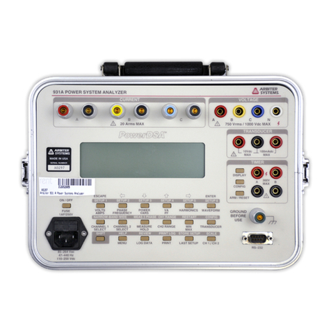
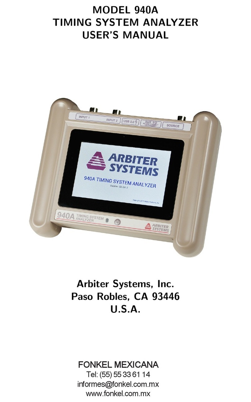
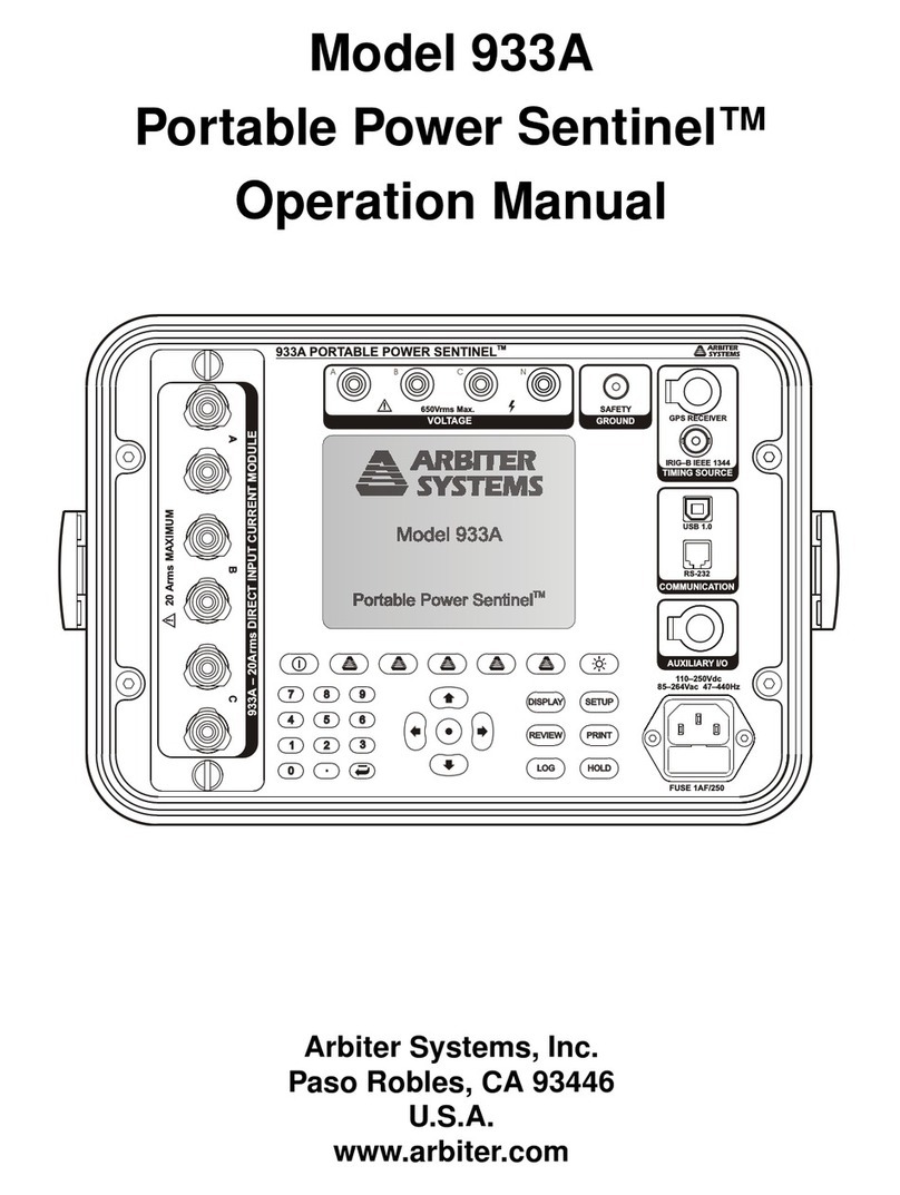
  9. Arbiter Systems 931A Installation and operating instructions

Arbiter Systems 931A Installation and operating instructions

APPLICATION NOTE 113
Arbiter Systems, Inc. 1324 Vendels Circle, Suite 121 Paso Robles, CA 93446 1
Tel +1 805 237 3831 800 321 3831 Fax +1 805 238 5717 E-Mail [email protected]
Using Clamp-On Current Transformers (CTs)
with Arbiter Power Analyzers
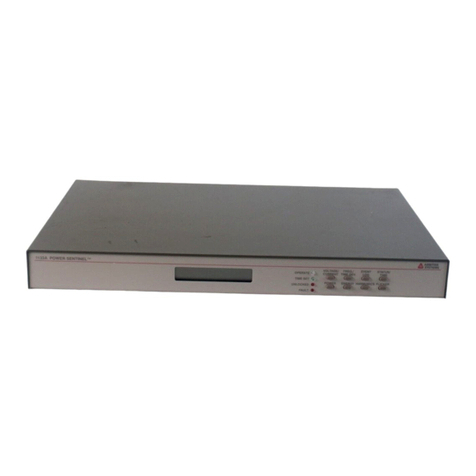
Model 931A Power Analyzer
Model 930A Three-Phase Power Analyzer
Model 929A Three-Phase Power Meter
Introduction
This application note deals with extending the
current measuring range of the Arbiter Models
931A, 930A and the Model 929A power
analyzers. It also covers techniques to greatly
improve the accuracy, and essentially calibrate
out the measurement inaccuracies associated
with the use of clamp-on current transformers
(CTs).
All three Arbiter power analyzers are state-of-
the art instruments offering unprecedented
accuracy in the measurement of parameters
related to AC Power Generation, Transmission,
and Distribution. Frequently, however, direct
measurements are not possible since the
parameter being measured is beyond the range
of the instrument, or the circuit cannot be
disconnected. One such electrical parameter is
current. Since each of these instruments is
limited to measure up to 20 Amps directly, an-
other method is needed to extend the measure-
ment range beyond 20 Amps.
Employing the use of a clamp-on current trans-
former, with a known ratio (e.g. 100:1), can
effectively extend the current measuring range
of these Arbiter products, and not interrupt the
circuits being tested. One of the negative
aspects of using a clamp-on current transformer
is the measurement error due to accuracy and
phase shift introduced by the clamp-on CT.
Since these measurement errors can be
accounted for by using the scaling feature on
these power analyzers, using a clamp-on CT
should no longer be a concern.
Lastly, this application note will review a very
simple technique in calibrating the CT for use
in the field or in the lab.
Theory of Operation
An AC clamp-on current probe (CT) is a type
of current transformer. A transformer is formed
essentially from two coils wound on a common
iron core (Figure 1). A current I1 applied
through the coil B1 induces through the
common core a current I2 in coil B2. The
current I2 in B2 is determined by the ratio N1 x
I1 = N2 x I2, where N1 and N2 are the number
of turns in each coil.
I1
B1
I2
B2
Iron Core
Z
Figure 1
The same principle is applied to a current
probe, which is simply an articulated magnetic
core (Figure 2). The articulated core holds the
coil B2, and clamps over the conductor being
measured. If B1 is the conductor being
measured, then N1 is the number of turns of
that conductor, which is normally equal to one.
When the current probe is clamped around the
conductor it provides an output proportional to
the number of turns of B2, such that
I2 (probe output) = (N1 / N2) x I1 where N1 =
1, or the probe output = I1 / N2. Without a CT
APPLICATION NOTE 113
2Arbiter Systems, Inc. 1324 Vendels Circle, Suite 121 Paso Robles, CA 93446 Tel
+1 805 237 3831 800 321 3831 Fax +1 805 238 5717 E-Mail [email protected]
it would be difficult to measure currents that
are beyond the measuring range of the
instrument. Also, by making the number of
turns on the current probe equal to an even
multiple (e.g. 1000:1), it is easy to provide
direct readings.
Conductor
B1 (N1)
Probe Jaws
mA or A range
on instrument
B2 (N2) I2
I1
Current
Producer
Figure 2
If N2 equals 1000, then the clamp has a ratio of
1/1000, which can be written as 1000:1.
Another way to say the same thing is to say that
the probe output is 1 mA/A (one milliampere
per Amp).
Current probes may be used with a variety of
instruments, including multimeters that require
the user to make mental corrections for the
scaling of the probe. For example, if the probe
ratio were 1000:1 a 50 A current would read as
50 mA on a multimeter using the milliampere
range. Users need to interpret the reading
correctly as amps and not milliamperes.
Additionally, any errors due to accuracy or
phase shift introduced by the current probe
need to be accounted for. If the current reading
was 50 mA and the current probe has an
accuracy of 1% with a phase shift of 3°, these
corrections must be computed.
Scaled Readings on the Model 931A /
930A / 929A
Arbiter’s Power Analyzers solve this problem
by allowing the user to program these scaling
values into memory. Current probe ratios may
be programmed into the Model
931A/930A/929A to provide a direct readout of
the current. For a probe with a ratio of 1000:1,
1000.0 could be programmed into these power
analyzers to provide a direct reading of current.
It would not, however account for the
inaccuracy and phase shift of the probe.
In order to account for these errors, of the
actual current probe being used, a simple
calibration setup is required. Basic equipment
could be the Arbiter Model 1040C Panel Meter
Calibrator, or other current source, the test
leads and current probe and the Model 931A /
930A / 929A. Setup is pictured in Figure 3.
MODEL 1040C
A
BC
MODEL 931A/930A/929A
VOLTAGE
CURRENT
CLAMP-ON CURRENT PROBE
TEST LEADS
MEASURING INSTRUMENT
CURRENT SOURCE
Figure 3
Figure 3 demonstrates a method of com-
pensating for the inaccuracy and phase shift
introduced by the current probe. By using a
current reference (measured by a Model
931A/930A/929A) reading current directly
from the source of current (the Model 1040C
Panel Meter Calibrator) the current probe may
be compared to the known reference.
APPLICATION NOTE 113
Arbiter Systems, Inc. 1324 Vendels Circle, Suite 121 Paso Robles, CA 93446 3
Tel +1 805 237 3831 800 321 3831 Fax +1 805 238 5717 E-Mail [email protected]
Additionally, the same meter that reads the
reference current also measures the probe
current, reducing equipment and other
calibration errors.
Since the Model 931A/930A/929A measures
true RMS values to 0.05% (3 kHz bandwidth),
any source of current may be used for
reference. It is important to make Channel A
the direct reference channel, and make Channel
B or C the channel to be calibrated (using the
current probe).
Calibrating the Power Analyzer
Set up the power analyzer as follows:
1. Switch on the power to the unit and wait for
it to show both channels.
2. Press the Channel 1 Select key and use the
cursor movement keys to select Channel 1
as Ia.
3. Press the Channel 2 Select key and use the
cursor movement keys to select Channel 2
as Ib.
4. Set the SCALE for Ib to the nominal CT
ratio (e.g. 100.00, see example 1).
5. Connect the direct current source to current
input A (Channel 1) and the current probe
leads to current input B (Channel 2).
6. Use a current amplitude near the value to be
measured. Make certain that the current
source to the Power Analyzer is less than
20 Amps.
7. Clamp the current probe over one of the
leads of current input A leads
8. If the current source is ON, then the CH1
and CH2 on the power analyzer should be
indicating two measurements very close in
value.
9. Press the CH1 / CH2 key and the analyzer
will mathematically compare Channel 2 to
Channel 1, and provide the exact magnitude
and phase values to program in to the
power analyzer.
10. Press the SHIFT and SCALE keys to view
the various scale values. Use the cursor
keys to move to Ib and press ENTER.
11. Use the cursor keys again to select the
correct digit and numerical scale value for
magnitude. When the value is correct –
with decimal point – press ENTER.
12. Repeat the procedure in 8 and 9 for phase
difference (between A and B).
The probe should now be calibrated to the
power analyzer, read current directly and
compensate for errors in magnitude and phase
shift. Three examples follow.
Calibrated Example 1
PROBE: AEMC Model MN170, Clamp-on Current
Probe, 100:1 ratio and maximum input current of 75
Amps
Using a Model 1040C as a current source, a
Model 931A to measure current, calibration
was performed at 5 Amps. Measurements at
other values were as follows:
1040C CH A CH B CH1/CH2 φ°
0.1 0.1000 0.1000 1.0004 0.21
1.0 1.0007 1.0014 0.9994 0.18
2.0 2.0003 2.0012 0.9995 0.13
3.0 3.0000 3.0008 0.9997 0.08
4.0 4.0004 4.0010 0.9999 0.04
5.0 5.0019 5.0020 1.0000 0.00
From left to right, the first three rows are in
amps. The fourth row is dimensionless (A/A),
and the last row is the phase difference in
degrees between the two measurement channels
(Channel 2 compared to 1).
APPLICATION NOTE 113
4Arbiter Systems, Inc. 1324 Vendels Circle, Suite 121 Paso Robles, CA 93446 Tel
+1 805 237 3831 800 321 3831 Fax +1 805 238 5717 E-Mail [email protected]
The screen above shows the nominal CT scale
setting prior to actual calibration.
In this example, the Model 931A was con-
nected as in Figure 3 with only the advertised
current probe ratio programmed in for the
magnitude of Ib. With only one turn for N1, the
programmed scale value for Ia (N1) was
1.0000, and the programmed scale value for Ib
(N2) was 100.00. Next, the current source is
applied and the VOLTS/AMPS key was
pressed to observe the Ia and Ib readings
stabilize.
After this the CH1/CH2 key was pressed to
observe the current ratio, for magnitude and
phase.
With a magnitude ratio of 1.0064 and a probe
turns ratio of 100, multiply the ratio above by
100 to get 100.64 and enter this value in for Ib
magnitude. Do the same for the phase error
between Ia and Ib of 2.47 degrees. When
complete, current Ib should agree with current
Ia at the same current that the ratios were
determined. See the screen printout from the
Model 931A scale values.
Incidentally, if higher current values need to be
calibrated (beyond the range of the
Model931A) a coil of wire may be substituted
for N1. This method limits the direct current to
the Model 931A but increases the apparent
current sensed by the probe. This procedure
will be explained in the next example
Calibrated Example 2
PROBE: AEMC MD304, Clamp-on current probe,
100:1 ratio and 600 Vrms maximum input voltage
In this second example we want to calibrate the
probe at a current of 125 Amps. However, with
a current source limit of 7 Amps and maximum
measuring limit (with the Model 931A) of 20
Amps, another method is required.
A coil of wire with a known number of turns
can replace a high current source for the probe.
The Model 931A can be scaled to the desired
ratio. In this example we used a 25-turn coil
and set Channel 1 (A) to a turns ratio of 25 (for
N1) instead of 1. This was done to make both
readings agree for better comparison and
consistent ratio. The screen below illustrates
how the initial scale factors were set to arrive at
a calibrated scale. See test setup with coil of
wire in Figure 4.
APPLICATION NOTE 113
Arbiter Systems, Inc. 1324 Vendels Circle, Suite 121 Paso Robles, CA 93446 5
Tel +1 805 237 3831 800 321 3831 Fax +1 805 238 5717 E-Mail [email protected]
MODEL 1040C
A
BC
MODEL 931A/930A/929A
VOLTAGE
CURRENT
CLAMP-ON CURRENT PROBE
TEST LEADS
MEASURING INSTRUMENT
CURRENT SOURCE
Coil of Wire
Figure 4
With these initial scale factors installed, we
adjusted the current to 5 Amps and read the two
currents as follows:
Next, we press the CH1/CH2 key to get the
current magnitude and phase ratios.
With these two ratios we can install these
calibration scale factors and make some
measurements.
For negative, phase-angle, scale factors it is
necessary to move the cursor to one digit to the
left of the most-significant digit to get the
negative sign.
After installing the above probe scaling we
made some measurements at simulated cur-
rents, shown below.
1040C CH1 CH2 CH1/CH2 φ°
1.0 25.076 24.407 1.0277 0.83
2.0 50.260 49.583 1.0091 0.17
3.0 75.329 74.628 1.0089 0.17
4.0 100.35 99.985 1.0037 0.06
5.0 125.42 125.40 1.0001 -0.01
6.0 150.55 150.95 0.9973 -0.06
From left to right, the first three rows are in
amps. The fourth row is dimensionless (A/A),
and the last row is the phase difference in
degrees between the two measurement channels
(Channel 2 compared to 1).
Calibrated Example 3
PROBE: AEMC SD601A Clamp-on current probe,
1000:1 ratio and 1000 Amps maximum input
In example 3 we want to calibrate the probe at
a current of 500 Amps. However, with a
current source limit of 7 Amps and maximum
measuring limit (with the Model 931A) of 20
Amps, we will use the same method as in
example 2 but with a larger coil.
A coil of wire with a known number of turns
can replace a high current source for the probe.
The Model 931A can be scaled to the desired
ratio. In this example we used a 100-turn coil
and set Channel 1 (A) to a turns ratio of 100
(for N1) instead of 1. This was done to make
both readings agree for better comparison and
consistent ratio. The screen below illustrates
how the initial scale factors were set to arrive at
a calibrated scale.
APPLICATION NOTE 113
6Arbiter Systems, Inc. 1324 Vendels Circle, Suite 121 Paso Robles, CA 93446 Tel
+1 805 237 3831 800 321 3831 Fax +1 805 238 5717 E-Mail [email protected]
With these initial scale factors installed, we
adjusted the current to 5 Amps and read the two
currents as follows:
Next, we press the CH1/CH2 key to get the
current magnitude and phase ratios.
With these two ratios we can install these
calibration scale factors and make some
measurements.
For negative, phase-angle, scale factors it is
necessary to move the cursor to one digit to the
left of the most-significant digit to get the
negative sign.
After installing the above probe scaling we
made some measurements at simulated cur-
rents, shown below.
From left to right, the first three rows are in
amps. The fourth row is dimensionless (A/A),
and the last row is the phase difference in
degrees between the two measurement channels
(Channel 2 compared to 1).
1040C CH1 CH2 CH1/CH2 φ°
5.0 501.98 502.00 1.0000 0.00
4.0 401.87 401.89 1.0000 0.02
3.0 301.28 301.13 1.0005 0.03
2.0 200.50 200.80 0.9985 0.06
1.0 100.31 100.58 0.9973 0.10
Summary
Using a current probe and any of the Arbiter
power analyzers (Model 931A / 930A / 929A)
it is possible to make very accurate measure-
ments outside the range of the instrument.
Secondly, it is possible to account for the
magnitude and phase angle inaccuracies due to
using a current probe. By doing this, the above
measurements can be very accurate.
Other devices can also be used to increase the
range of the Arbiter Power DSA series of
analyzers. One of these is the 400-Amp
precision CT described below.
Accessories
400 Amp Direct Input Adapter
Arbiter also produces a 400-Amp, 20:1 pre-
cision CT. This is a direct input CT adapter,
with 0.1% accuracy over the full range. It
attaches to the power analyzer current input
terminals with lugs. Order part number
09311A.

Other manuals for 931A

1

This manual suits for next models

2

Other Arbiter Systems Measuring Instrument manuals

Arbiter Systems 1133A User manual

Arbiter Systems

Arbiter Systems 1133A User manual

Arbiter Systems 1040C Installation guide

Arbiter Systems

Arbiter Systems 1040C Installation guide

Arbiter Systems 940A User manual

Arbiter Systems

Arbiter Systems 940A User manual

Arbiter Systems 931A User manual

Arbiter Systems

Arbiter Systems 931A User manual

Arbiter Systems 940A User manual

Arbiter Systems

Arbiter Systems 940A User manual

Arbiter Systems 1092A User manual

Arbiter Systems

Arbiter Systems 1092A User manual

Arbiter Systems 921A Guide

Arbiter Systems

Arbiter Systems 921A Guide

Arbiter Systems Portable Power Sentinel 933A User manual

Arbiter Systems

Arbiter Systems Portable Power Sentinel 933A User manual

Popular Measuring Instrument manuals by other brands

PROLEC PME 500 Operator's manual

PROLEC

PROLEC PME 500 Operator's manual

PTC Instruments 511A-Type A manual

PTC Instruments

PTC Instruments 511A-Type A manual

SKF TMRT 1 Instructions for use

SKF

SKF TMRT 1 Instructions for use

Soilmoisture Equipment 6085 Handi-TRASE quick start guide

Soilmoisture Equipment

Soilmoisture Equipment 6085 Handi-TRASE quick start guide

HUBER INSTRUMENTE TM40 operating manual

HUBER INSTRUMENTE

HUBER INSTRUMENTE TM40 operating manual

Littelfuse Startco SE-135 manual

Littelfuse Startco

Littelfuse Startco SE-135 manual

Sub-Zero SZ-7505T operating instructions

Sub-Zero

Sub-Zero SZ-7505T operating instructions

Dataq DI-700 user manual

Dataq

Dataq DI-700 user manual

Agilent Technologies 1670G Series Service guide

Agilent Technologies

Agilent Technologies 1670G Series Service guide

Johnson 1454-0000 instruction manual

Johnson

Johnson 1454-0000 instruction manual

Drawell DR Series user manual

Drawell

Drawell DR Series user manual

KROHNE OPTIMASS 2400 quick start

KROHNE

KROHNE OPTIMASS 2400 quick start

inbody BSM270 user manual

inbody

inbody BSM270 user manual

Control Systems 3B6 SLIM Calibration manual

Control Systems

Control Systems 3B6 SLIM Calibration manual

Sierra InnovaSonic 205i instruction manual

Sierra

Sierra InnovaSonic 205i instruction manual

Solartone Metrology WIGAUGE User and installation manual

Solartone Metrology

Solartone Metrology WIGAUGE User and installation manual

Entes EVM-R3 quick start guide

Entes

Entes EVM-R3 quick start guide

PASCO WA-7428 Product guide

PASCO

PASCO WA-7428 Product guide

manuals.online logo
manuals.online logoBrands
  • About & Mission
  • Contact us
  • Privacy Policy
  • Terms and Conditions

Copyright 2025 Manuals.Online. All Rights Reserved.