Stricker City User manual

General User Manual
R&E Stricker Reha-Entwicklungen GmbH
Model series
City
Ultra
Sport
Lomo360
Neodrives
Lipo Smart
Smart Wild
These operating manual are supplemented for models of the Neodrives, Lipo Smart
and Smart Wild model series by additional operating manual.

Misprints, mistakes and price or product changes reserved. Product changes include changes resulting from the
further development of the mechanics or the legal requirements.
Date: 10. June 2021
®R&E Stricker Reha-Entwicklungen GmbH , Bühl
Reprint, even in part, only with the written permission ofR&E Stricker Reha-Entwicklungen GmbH , Bühl.
Manufacturer
R&E Stricker Reha-Entwicklungen GmbH
Klotzberg 64
D-77815 Bühl
Phone: +49 7223/72510
Fax : +49 7223 / 74947
Email: [email protected]
Web: www.stricker-handbikes.de
Notice to reader
For reasons of readability, the masculine form has been chosen in these instructions for use, nonetheless
the information relates to members of all genders.

R&E Stricker Reha-Entwicklungen GmbH
1
Manual Handbikes
Table of Contents
1 Declaration of Conformity ..................................................................................................................3
2 Introductory notes..............................................................................................................................3
3 Model note Lipo Smart and Neodrives................................................................................................3
4 Product Description & Intended Use ...................................................................................................4
5 Safety and driving instructions for accident prevention ......................................................................4
5.1 Safety instructions ......................................................................................................................................4
5.2 Safety checks ..............................................................................................................................................4
5.3 Driving instructions .....................................................................................................................................5
6 Condition of the wheelchair................................................................................................................6
7 Commissioning ..................................................................................................................................6
8 Fitting the handbike to the wheelchair and the rider............................................................................6
8.1 Unpacking the handbike .............................................................................................................................7
8.2 Adjusting the inclination of the headstock tube........................................................................................7
8.3 Mounting the handles and cranks..............................................................................................................7
8.4 Adjusting the length and width of the clamping device............................................................................7
......................................................................8
8.6 Adjusting the crank position.......................................................................................................................8
8.7 Adjusting the crank height..........................................................................................................................9
8.8 Adjusting the ground clearance .................................................................................................................9
9 Coupling the handbike to the wheelchair ..........................................................................................11
10 Uncoupling the handbike from the wheelchair ..................................................................................11
11 Steer ................................................................................................................................................12
11.1 Function of the steering damper............................................................................................................. 12
12 Breaks..............................................................................................................................................12
12.1 Coaster brake ........................................................................................................................................... 12
13 Shifting ............................................................................................................................................13
13.1 Hub gear ................................................................................................................................................... 13
13.2 Derailleur................................................................................................................................................... 13
13.3 Planetary gear Mountain-Drive................................................................................................................ 13
14 Kickstand.........................................................................................................................................13
14.1 Standard equipment................................................................................................................................. 13
14.2 Special equipment quick adjustment ..................................................................................................... 14

2
R&E Stricker Reha-Entwicklungen GmbHManual Handbikes
15 Repair, cleaning and maintenance ....................................................................................................14
15.1 Cleaning and care..................................................................................................................................... 14
15.2 Air pressure of the drive wheel................................................................................................................ 14
15.3 Clamping device....................................................................................................................................... 14
15.4 Automatic catch....................................................................................................................................... 15
15.5 V-Brake...................................................................................................................................................... 15
15.6 Disc brake ................................................................................................................................................. 16
15.7 Toothed belt drive .................................................................................................................................... 18
15.8 Chain drive................................................................................................................................................ 18
15.9 Planetary gear Mountain-Drive................................................................................................................ 19
16 Transport .........................................................................................................................................19
16.1 Transportation in vehicle ......................................................................................................................... 19
16.2 Airplane transportation............................................................................................................................ 19
17 Disposal and recycling .....................................................................................................................19
18 Warranty and guarantee ...................................................................................................................20
19 Liability ............................................................................................................................................20
Attachment ............................................................................................................................................22
A Technical data City................................................................................................................................... 22
B Technical data City Max .......................................................................................................................... 22
C Ultra technical data .................................................................................................................................. 23
D Technical data sport ................................................................................................................................ 23
E Torque list ................................................................................................................................................. 23

R&E Stricker Reha-Entwicklungen GmbH
3
Manual Handbikes
Declaration of Conformity
1 Declaration of Conformity
The device complies with the current standards and guidelines of the EU. We certify this in the EC
declaration of conformity. If required, we will be happy to send you the corresponding declaration of
conformity. Our power assist devices have been tested by means of an electromagnetic compatibility test
(EMC).
In the event of a change not agreed with R&E Stricker GmbH, this declaration loses its validity.
MDR
devices - Stricker Handbikes) comply with the essential requirements according to the new regulation
(EU) 2017/745 (MDR) or the Medical Devices Act. The documentation of the production is available at
the company R&E Stricker Reha-Entwicklungen GmbH. R&E Stricker Reha-Entwicklungen GmbH holds full
responsibility for the issuance of the declaration of conformity.
2 Introductory notes
WARNING
Before operating the handcycle, please read these operating instructions and all other supplied operating
instructions carefully and observe them.
WARNING
Visually impaired persons or persons with cognitive impairments must have the information material and
operating instructions read aloud by assistants. Corresponding documents are available on our website
www.stricker-handbikes.de on the Internet. Videos and photos are also available there.
DEALER NOTICE
It is imperative that you hand over these operating instructions to each customer when handing over the
handbike and expressly draw the customer’s attention to the safety and danger instructions.
Never deliver a handbike without operating instructions!
3 Model note Lipo Smart and Neodrives
WARNING
If you have received this General User Manual for a handbike of the Lipo Smart or Neodrives model series,
please read both this General User Manual and the additional user manual supplied with the respective
model series.
It is imperative that you hand over these operating instructions to each customer when handing over the
handbike and expressly draw the customer’s attention to the safety and danger instructions.

4
R&E Stricker Reha-Entwicklungen GmbHManual Handbikes
Product Description & Intended Use
4 Product Description &
Intended Use
The handbike is coupled to a manual wheelchair as
a manual traction aid. This allows the driver to be
supported in his mobility. The aim is to extend the
range of action by making it easier to cover longer
distances independently. Coupling the handbike
creates a three-wheeled vehicle with three relatively
large wheels. The handbike therefore improves
driving characteristics on uneven surfaces.
Obstacles can also be overcome more easily.
Driving downhill and on slopes becomes safer due
to the additional braking systems. The handbike
can be independently coupled to and released
from the wheelchair by the rider. The wheelchair as
such is not changed and its properties remain fully
intact.
5 Safety and driving
instructions for accident
prevention
WARNING
These instructions are for your own safety.
Please read them carefully before operating the
hand bike and observe the instructions! Failure
to observe the operating instructions could result
in damage to the product as well as serious
personal injury. We accept no liability for damage
resulting from failure to observe the operating
instructions.
NOTE
Observe all safety and hazard information and
instructions, both in this and in all other operating
instructions supplied.
5.1 Safety instructions
For your own safety, do not go without a bicycle
helmet when riding a handcycle.
5.1.1 Permitted speed
Be sure to comply with the legal regulations of the
country in which you operate the handbike. The
hand bike is approved for a maximum speed of
25 km/h. On steep inclines, you may only ride at
brake safely at all times.
5.1.2 Permitted payload
The maximum load of the handbike is 120 kg. The
manufacturer may limit this. Use the lower value as
a guide.
5.1.3 Users with small children
In the interest of the child, please refrain from
riding a handbike with a child on your lap. There is
a high risk of injury from the toothed belt or chain
and from the rotating cranks.
5.2 Safety checks
WARNING
Carry out the following safety checks before every
journey. These are primarily for your safety and
the safety of all other road users.
5.2.1 Air pressure
Check the air pressure of the handbike and
wheelchair tires. The air pressure of the handbike
tire should be about 3-4 bar, the air pressure of
the wheelchair drive wheels about 5-7 bar. For the
exact maximum values, please refer to the imprint
on the respective tire. Too low an air pressure of
the wheelchair wheels increases the risk of tipping
over, especially in curves!
5.2.2 Secure t of all components
Check all components, especially all screws, for
be checked particularly carefully and tightened if
necessary to exclude twisting. For the exact torque
values, please refer to “E Torque list”.
5.2.3 Straight run
Determine whether the drive wheel is aligned
centrally to the wheelchair. The wheel must be in
the center of the wheelchair track. Deviations of no
more than 1 cm from the center are permissible. If
necessary, use the instructions from “9 Coupling
the handbike to the wheelchair”.
The double-acting steering return supports
straight-ahead running. Detailed information or
setting instructions can be found in “11.1 Function
of the steering damper”.
WARNING
An incorrectly aligned drive wheel can lead to
accidents due to poor straight-ahead running and
vibrations.

R&E Stricker Reha-Entwicklungen GmbH
5
Manual Handbikes
Safety and driving instructions for accident prevention
5.2.4 Braking
Check whether the braking power of your handbike
settings of the brakes (“15.5 V-Brake” and “15.6
Disc brake”). Note that weather conditions, the
road surface and the weight of the handbike and
distance.
Make sure that the parking brakes of your
wheelchair are set correctly. Always use the
parking brakes to secure your vehicle against
unintentional rolling away, especially when parking
on sloping surfaces. Avoid parking on sloping
surfaces if possible.
Ensure that the coaster brake detent button is fully
engaged. Also test the function of the automatic
back-pedal engagement (“12.1 Coaster brake”).
5.2.5 Toothed belt
Check the toothed belt for mechanical damage and
irregularities.
Check the tension of the toothed belt and adjust
the belt if necessary (“5.2.5 Toothed belt”).
5.3 Driving instructions
5.3.1 Getting used to the handbike
WARNING
Always adjust your driving to the degree of your
disability.
WARNING
Always drive only fast enough to be able to
brake safely at any time, even in unforeseeable
situations! This applies especially to downhill
driving.
WARNING
Always hold the cranks with both hands when
riding and braking to reduce the risk of accidents.
Safe control of the combination of wheelchair and
handbike requires some practice. Cautious and
slow riding is particularly useful for beginners.
Avoid mountainous terrain and bad roads at the
beginning until you have familiarized yourself with
the driving characteristics of the handbike.
By attaching the handbike to your wheelchair,
the four-wheeled wheelchair becomes a tricycle
with various advantages and disadvantages. In
curves, a tricycle is more unstable than a normal
wheelchair! In the beginning, familiarize yourself
with the new driving and tilting behavior by driving
carefully. Avoid jerky steering movements at all
costs!
Also slowly get used to the higher speeds that can
be reached with the handbike. Adjust your speed to
5.3.2 Driving at dusk and darkness
Always switch on the built-in lighting for rides at
dusk and in the dark. Attach the supplied rear light
to the back of your wheelchair. Always check the
batteries for the rear light before driving off and
have new ones ready.
5.3.3 Risk of falling
Avoid jerky steering movements at all costs!
Drive at a slow speed, especially in curves and in
unclear situations. Tilt your upper body towards the
inside of the curve (like a cyclist) to avoid tipping
over the wheelchair.
With narrow wheelchairs and little camber of the
wheelchair’s drive wheels, the lateral tipping hazard
is particularly high. To reduce the risk of tipping, we
recommend our track widening Kippex.
To avoid the risk of falling, do not perform the
following maneuvers with the handcycle:
• Driving over several steps or landings
• Driving over a curb at an angle
• Turning on sloping roads
• Quick steering movements
• Abrupt braking in curves
• Braking too hard on wet roads
Reduce your speed when transitioning between
slopes and level terrain.
negative camber of the wheelchair’s rear wheels.
5.3.4 Mountain rides
If the incline is too steep, the drive wheel can lose
grip and spin. To improve the climbing ability,
you can equip your handbike with a wheelbase
extension and additional weights. These also have
a positive effect on traction on unpaved paths and
braking behavior. Avoid attaching weight (e.g. a
backpack) to the back of the wheelchair. It is better
to use a luggage carrier at the front.

6
R&E Stricker Reha-Entwicklungen GmbHManual Handbikes
Condition of the wheelchair
WARNING
If the drive wheel slips when driving downhill, it
may be necessary to additionally apply the brakes
of the wheelchair.
6 Condition of the wheelchair
Your handbike can be mounted to different
wheelchairs. For this purpose, your wheelchair
should be in a technically perfect condition. Do not
use a wheelchair that has already undergone major
repairs to the frame. We recommend wheelchairs
with rigid frames, as these offer greater stability
for use with a handbike than folding wheelchairs.
Nevertheless, most folding wheelchairs are
suitable for combination with our handbikes. If you
have any questions about your wheelchair model or
a planned new purchase, please contact us.
Make sure that the brakes of the wheelchair are in
perfect condition.
Despite the attached handbike, you can move the
wheelchair normally by driving the rear wheels.
This means that driving forwards and backwards
is possible without restriction. Steering by moving
the wheelchair wheels is only possible to a limited
extent due to the automatic steering reset.
7 Commissioning
Instruction is provided by a dealer, a medical
or a Stricker employee at R&E Stricker GmbH on
site. We recommend involving an assistant for
instruction and commissioning who can later
provide handling support if necessary.
at low speed and familiarize yourself with the
handcycle. Always adapt the speed and driving
maneuvers to your own ability, the external
regulations. After a short time you will get a feeling
for the handbike. Before you ride the handbike on
slopes, inclines or uneven terrain, learn how to
8 Fitting the handbike to the
wheelchair and the rider
NOTE
Unpacking and installation video can be found on
www.stricker-handbikes.de/installationsupport
WARNING
Ensure that all screws are tightened to the
appropriate torques after adjustment is complete.
The corresponding torques can be found in the
following instructions and in “E Torque list”.
Screws that are not tightened properly pose a
injuries.
Fig. 1: City

R&E Stricker Reha-Entwicklungen GmbH
7
Manual Handbikes
Fitting the handbike to the wheelchair and the rider
Fig. 2: Standard frame
8.1 Unpacking the handbike
The handbike is tied up in the box for transport. Cut
the cord before removing the handbike.
For transport, both handles are removed and
both longitudinal tubes are twisted upwards. The
assembly and settings of the parts are explained
below.
NOTE
To perform all adjustments, place the handcycle
and your wheelchair securely on level, solid
ground. Make sure there is enough space and
light to carefully implement the adjustments.
8.2 Adjusting the inclination of
the headstock tube
WARNING
Make sure that the corner brackets secured by the
S1L and S1R screws do not slip out of the cross
tubes. Do not use the insertion depth of the corner
brackets to adjust the width of the clamping
device.
Loosen the S1L and S1R screws (Fig. 2) using the
Allen key (SW 6) provided. Turn the longitudinal
tubes to the desired angle to the control bearing
adjustment of the crank position, you may have to
adjust the angle again. Lightly tighten the S1L and
S1R bolts.
After completing all adjustments, tighten the S1L
and S1R screws to a torque of 30 Nm.
NOTE
If you make adjustments to the inclination of the
headset tube while the handbike is coupled to the
wheelchair, also loosen the S3L and S3R screws
to prevent tension in the frame. Tighten them
again afterwards with a torque of 30 Nm.
8.3 Mounting the handles and
cranks
If necessary, place the cranks back in place and
tighten the screws to a torque of 25 Nm. Make sure
that the cranks on a handbike are aligned in the
same way as on a bicycle.
Screw the two handles to the cranks and tighten
the screws (SW15) with a torque of 20-25 Nm.
8.4 Adjusting the length and
width of the clamping device
To adjust the length of the longitudinal tubes and
the angle of the clamps, loosen screws S3L and
S3R. Make sure that the length of the longitudinal
tubes is always set identically on both sides
(Fig. 3).
Adjust the angle of the clamps according to the
wheelchair frame at the clamping position. This is
especially important for wheelchairs with V-shaped
frames. Lightly tighten the S3L and S3R screws.
After completing all adjustments, tighten the S3L
and S3R screws to a torque of 30 Nm.
NOTE
If you make adjustments to the length of the
longitudinal tubes while the handbike is coupled
to the wheelchair, also loosen the S2L and S2R
bolts to avoid tension in the frame.
To adjust the width of the clamping device, loosen
the S2L and S2R screws. Adjust the clamping
device to the width of the wheelchair frame. Make
sure to set the same angle to the cross tube on
both sides (Fig. 3). Lightly tighten the S2L and S2R
screws. After completing all adjustments, tighten
the S2L and S2R screws to a torque of 30 Nm.

8
R&E Stricker Reha-Entwicklungen GmbHManual Handbikes
Fitting the handbike to the wheelchair and the rider
Fig. 3: Setting the default frame
8.5 Coupling the handbike to the
wheelchair for the rst time
Make sure that the screws S1L and S1R as well as
S3L and S3R are only slightly tightened. A slight
adjustment according to the wheelchair should still
be possible. Make sure that the handbike stands
straight.
Align the wheel of the handbike exactly in the
center of the wheelchair track. A maximum
deviation of 1 cm from the center is permissible.
Use the footrest to check the alignment.
WARNING
An incorrectly aligned drive wheel can lead to
accidents due to poor straight-ahead running and
swinging tendencies.
To simplify the adjustment, you can make a
template (Fig. 4). Then drive the wheelchair up
to the template so that the wheels are the same
distance from the line of symmetry. Place the
drive wheel of the handbike exactly on the line of
symmetry.
Fig. 4: Template
A Front wheel
B Symmetry line
C Markings for the wheelchair front wheels
D Wheelchair front wheels
Couple the handbike to the wheelchair according to
8Coupling the handbike to the wheelchairll”. Then
follow the further adjustment instructions to adapt
the handbike exactly to you and your wheelchair.
8.6 Adjusting the crank position
Clamp the handbike to the wheelchair.
WARNING
Leave the front wheels of the wheelchair on the
ground. Make all adjustments only when the
wheelchair is parked. There is a considerable risk
of injury when making adjustments in the driving
position.

R&E Stricker Reha-Entwicklungen GmbH
9
Manual Handbikes
Fitting the handbike to the wheelchair and the rider
In this position, the distance from the drooping
cranks to the rider’s thighs should be approx.
or steeper to achieve the correct distance (“8.2
Adjusting the inclination of the headstock tube”).
If the hand grips are too close to or too far away
from the body, adjust the length of the clamping
device according to your wishes (“8.4 Adjusting
the length and width of the clamping device”).
WARNING
Before proceeding to the next step, tighten all
screws according to the “E Torque list” in the
appendix.
Raise the front wheels of the wheelchair and
thereby bring the handbike into driving position.
In this position, check all adjustments and make
further adjustments if necessary by repeating the
previous steps.
If the hand grips are too far away from the body
or touch the knees despite the adjustments made,
the crank height can be adjusted even further (“8.6
Adjusting the crank position”).
8.7 Adjusting the crank height
If an extended adjustment of the crank is
necessary, the distance of the crank unit from the
front axle can be changed. However, to do this,
the chain must be shortened or a corresponding
belt must be purchased and, if necessary, Bowden
cables must be adjusted. Please refer to the list
must not be exceeded in any case. For further
information and the order of the appropriate belt
lengths we are at your disposal.
City 7 with toothed belt
• 84.0 cm (Toothed belt 2080)
• 88.0 cm (Toothed belt 2160)
• 92.0 cm (Toothed belt 2240) (Standard)
• 93.6 cm (Toothed belt 2272)
• 95.2 cm (Toothed belt 2304)
• 100.0 cm (for head tube 2400 and toothed belt
2400)
City 7 with chain
• 92.0 cm default setting
• 83.0-95.0 cm in 1.5 cm steps
City Kid/Jugend with chain
• 79.0 cm default setting
• 75.0-79.0 cm in 1.5 cm steps
• 66.0-79.0 cm by shortening or removing chain
tensioning sleeve
Ultra
• 92.0 cm default setting
• 83.0-95.0 cm steplessly adjustable
Sport
• 92.0 cm default setting
• 75.0-89.0 cm steplessly adjustable
8.8 Adjusting the ground
clearance
Clamp the handbike to the wheelchair.
WARNING
Leave the front wheels of the wheelchair on the
ground. Make all adjustments only when the
wheelchair is parked. There is a considerable risk
of injury when making adjustments in the driving
position.
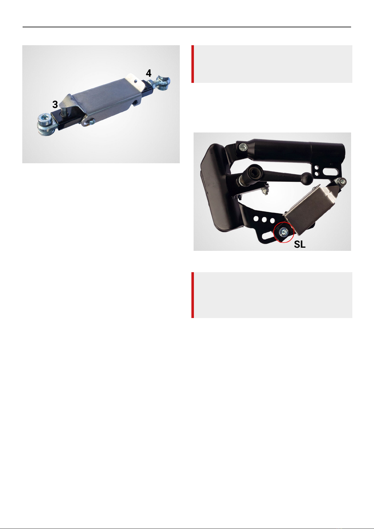
Fig. 5: Automatic catch open
10
R&E Stricker Reha-Entwicklungen GmbHManual Handbikes
Fitting the handbike to the wheelchair and the rider
Fig. 6: Automatic catch closed
1 Locking slot
2 Flap / Cover
3 Bolt
4 Nut
between the front wheels of the wheelchair and
the ground. The setting is made using the SL Allen
screw in the slotted hole adjustment. Set both
automatic notches in the same way. Open the grid
slot in the automatic latch. Move the Automatic
catch mechanism according to your wishes and
tighten the Allen screw SL with a torque of 30 Nm.
If the adjustment of the elongated holes is not
lock nut. Loosen the lock nut. Turn the adjusting
nut according to your requirements. Retighten the
lock nut after completing the settings.
frame and a cross bike, you may have to mount the
automatic catch differently (Fig. 6
loosen the screw SL with which the automatic latch
is attached in the elongated hole and unscrew
the screw completely. Remove the sleeve and all
washers. Make sure you slide the sleeve and all
washers back onto the appropriate screw in the
correct order.
Now loosen the lock nut on both Automatic catch
and completely unscrew the eyebolt. Also take the
adjusting nut out of the Automatic catch housing.
Install the sleeve from the eyebolt into the slot in
the housing of the automatic catch. Now mount
the screw SL again with all washers through the
Automatic catch-in housing in the elongated hole.
NOTE
Pay particular attention that the smaller washer
(shim washer) is in direct contact with the sleeve.
Otherwise there is a risk of damage to the parts.
with the screw SL. Therefore you have to bend
Fig. 7).
Tighten the screw SL with a torque of 30 Nm.
Fig. 7: Converted Automatic catch
WARNING
When lifting the front wheels into the driving
position, both locking pins must engage
simultaneously. This is absolutely necessary for
proper function.
The length of the latching slot provides a reference
point for the setting. When the handbike is parked,
about 1 cm of this should be visible. The longer the
visible part is in the parked position, the greater the
ground clearance in the driving position.
After adjustments have been completed, check the
ground clearance by lifting the front wheels of the
wheelchair into driving position. We recommend a
ground clearance of approx. 3-4 cm. Carry out the
previously described steps until the adjustment
meets your requirements. The adjustment of the
ground clearance may have an effect on the crank
position. Adjust this again if necessary.

R&E Stricker Reha-Entwicklungen GmbH
11
Manual Handbikes
Coupling the handbike to the wheelchair
9 Coupling the handbike to
the wheelchair
Once you have carefully adjusted the handbike to
your wheelchair, you can easily and quickly connect
and disconnect it from your wheelchair at any time.
If locked, unlock the Automatic catch. To do this,
release the locking pin. Now you can adjust the
clamping device and thus relax the automatic
detents to maximum length. We recommend that
you close the detents again immediately to avoid
injury when operating the clamping levers.
Open the clamping device on both sides just
enough so that they can be slid over the front
frame tubes of the wheelchair. Open the clamps
only as far as necessary, as opening them too far
could cause the clamping nuts to fall out (after
approx. 20 turns).
WARNING
Tighten the ball handle nut or the tetrastar nut
with a maximum torque of 6-8 Nm!
Grasp the handbike by the handlebar and attach
it to the front frame of the wheelchair using the
clamping device. Now tighten the clamps on both
sides.
For your own safety, we recommend locking the
brakes on the wheelchair and handbike for the
coupling process. This will prevent the handbike
or wheelchair from moving and you will have both
hands free to close the clamps.
To further simplify the coupling process, you
will receive positioning clamps together with the
handbike, which you can permanently mount on the
wheelchair. You can easily and safely position the
handbike’s clamping device on these and only have
to close the clamps.
NOTE
When closing the clamps, always make sure that
the clamps are aligned parallel to the tubes of
the front frame of the wheelchair. If this is not the
case, there is a risk of damage to the PVC caps.
Before coupling, make sure that the PVC caps
are undamaged. Damaged PVC caps can cause
damage to the wheelchair.
WARRANTY & LIABILITY NOTICE
The PVC caps are wearing parts, therefore no
warranty applies to them. We accept no liability
for damage caused by damaged PVC caps.
Now release the brakes of the handbike. Push the
handbike forward by the handlebar so that the front
wheels of the wheelchair lift off the ground. Push
the handbike forward until the automatic locks
engage on both sides. You should hear a distinct
click. Check whether both locking pins are visibly
engaged.
10 Uncoupling the handbike
from the wheelchair
Once you have carefully adjusted the handbike to
your wheelchair, you can easily and quickly connect
and disconnect it from your wheelchair at any time.
If locked, unlock the Automatic catch. To do this,
(Fig. 6 and Fig. 7
spring open and release the locking pin. Now you
can adjust the clamping device and thus relax
the automatic detents to maximum length. We
recommend that you close the detents again
immediately to avoid injury when operating the
clamping levers.
Open the clamping device on both sides just
enough so that they can be slid over the front
frame tubes of the wheelchair. Open the clamps
only as far as necessary, as opening them too far
could cause the clamping nuts to fall out (after
approx. 20 turns).
WARNING
As soon as you press the handbike forward by the
handlebar with the louvers open, the automatic
louvers unlock. You now hold the full weight.
force the detent bolts back. This could bend the
the function of the automatic detent.
Once you have parked the handcycle, you can
open the clamps and release the handcycle from
the wheelchair. Only open the clamps as far as
necessary, since if they are opened too far, the
clamping nuts could fall out (after approx. 20
turns).
12
R&E Stricker Reha-Entwicklungen GmbHManual Handbikes
Steer
11 Steer
Steer the handbike by turning the steering bearing
tube (handbike stem) using the crank handles. The
steering is equipped with a double-acting steering
damper, which ensures optimum directional
stability. For your own safety, avoid rapid steering
movements, especially when riding fast. There is a
risk of tipping over with the vehicle.
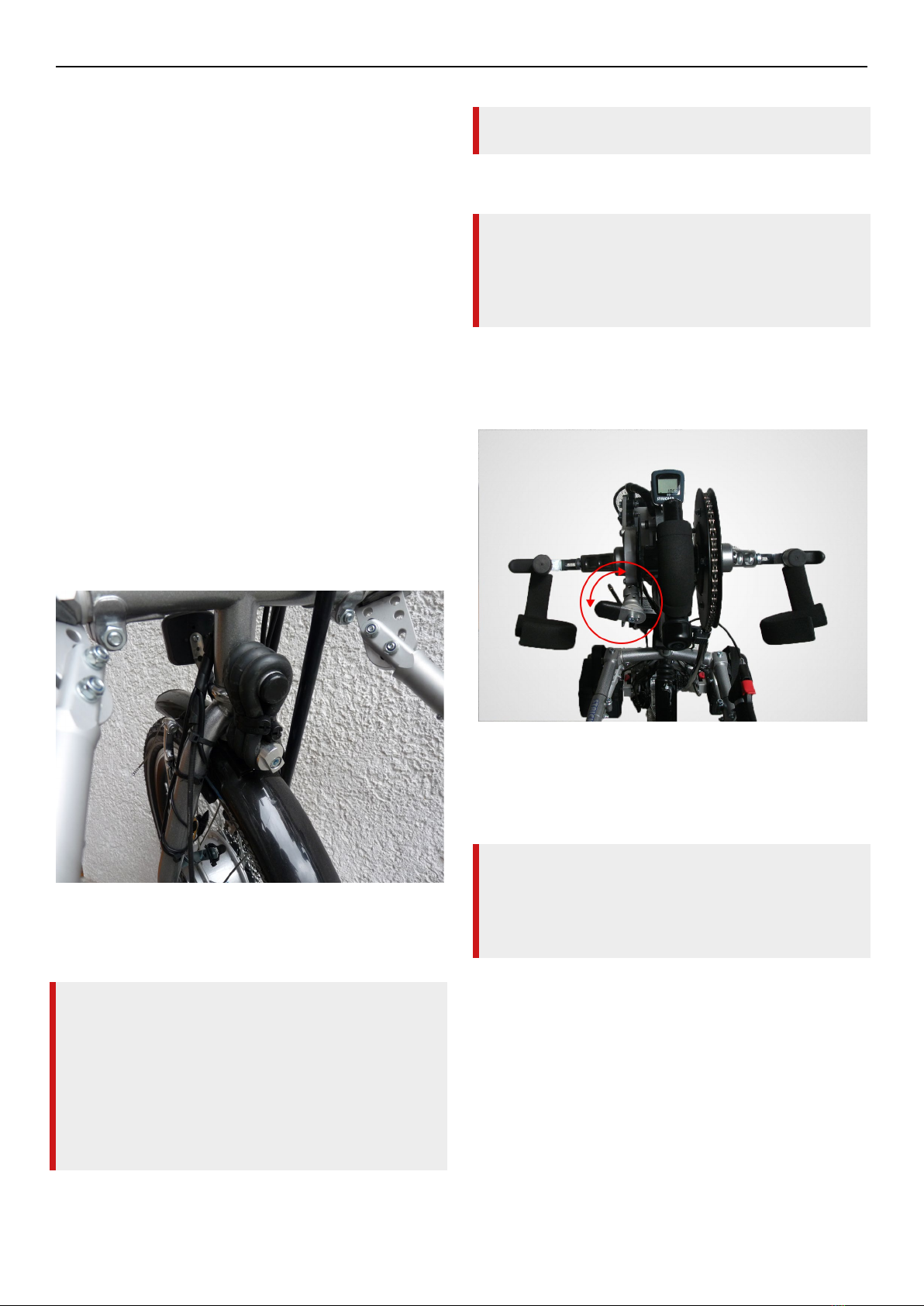
11.1Function of the steering
damper
The steering damper is located at the upper end
of the fork. Via the device, the steering is damped,
straight-line stability is supported and automatic
steering return is achieved. These functions are
provided by several steering damper rubbers.
There is a key milled hole (SW 13) on the lower
bolt of the tensioning rubbers. Turn this to the right
or left to adjust the fork and thus the straight run
(Fig. 8). If necessary, also open the nut on the front
of the fork.
Fig. 8: Steering damper setting
12 Breaks
SAFETY INFORMATION
The brakes are designed for a single-seat
handbike. Use on other vehicles or equipment
will void the warranty. Improper use may result in
serious personal injury.
For safety reasons, all models are equipped with
two independent brakes or a brake with two
independent operating mechanisms.
Before each ride, check the function of the brakes
and the brake pads for wear.
12.1Coaster brake
EQUIPMENT NOTE
All handbikes in the City model series, with the
exception of the City Max model, have the coaster
brake installed as standard. All other model series
offer the coaster brake only as an optional extra.
You can switch off the coaster brake for
maneuvering. Turn the detent lever 90 degrees
counterclockwise so that it remains in this position
(Fig. 9).
Fig. 9: Coaster brake
To switch on, turn the knob back to the starting
position. You can also activate the automatic
switch-on by turning the cranks forward.
NOTE
Before each ride, make sure that the detent button
is fully engaged, test the function of the automatic
backpedal switch and check the function of the
brake and the wear of the brake pads.
If the coaster brake is applied very strongly by
the cranks, the coaster may lock up, especially
in the three fastest gears. This will cause you to
on models with planetary gears, engage the
hill reduction by pressing the right button and
forcefully apply the coaster brake again. This
removes the blockage and you can start off again
normally.
R&E Stricker Reha-Entwicklungen GmbH
13
Manual Handbikes
Shifting
13 Shifting
13.1Hub gear
Shift the hub gears under load or without load or at
standstill. If you shift under high load, the shifting
process may only become effective if you move the
cranks as load-free as possible for a moment.
13.2Derailleur
Only shift the derailleur while riding. Do not shift
the derailleur when stationary or when the cranks
are not moving. For the repositioning of the
chain by the shifting process, the rotation of the
chainring by cranking is absolutely necessary. This
can be done under load or with load-free cranking.
13.3Planetary gear Mountain-
Drive
The planetary gearbox allows you to use a hill
reduction for riding on steep inclines. In standard
operation, the gears of your handbike are available
in a 1:1 ratio. In hill reduction mode, all gears are
force required for cranking.
To activate or deactivate the mountain reduction,
use the buttons on the right or left of the crank
axle.
Button pressed in on the left: standard gear ratio
1:1
Button pressed in on the right: Mountain reduction
2.5:1
MODEL NOTE CITY WITH HUB
BRAKE
With the downhill reduction switched on, there
is a longer distance before the braking effect
takes effect when the coaster brake is applied.
Therefore, for your own safety, switch back
to normal operating mode immediately after
mastering an incline. If you still have to brake with
the hill reduction activated, plan for the additional
distance until the braking process. In addition, you
can also use the handbrake to help.
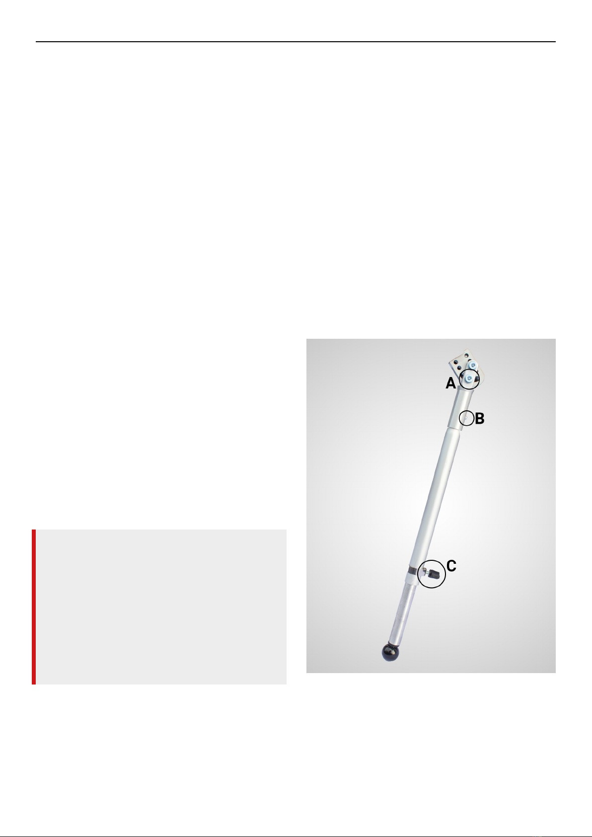
14 Kickstand
We offer attachable stands in various designs. All
designs are freely interchangeable with each other.
on our website and order directly from us.
To adjust the angle, loosen screw A. In the parked
position, the stand should touch the ground near
the front wheels of the wheelchair.
14.1Standard equipment
Loosen the thumbscrew C to adjust the length of
the Kickstand.
The Kickstand can remain on the handbike while
driving, as it is lifted off the ground just like the
front wheels of the wheelchair. For transporting
the handbike, you can remove the Kickstand tubes
if necessary. To remove the Kickstand tube, press
button B and pull off the Kickstand tube.
Fig. 10: Kickstand adjustment

14
R&E Stricker Reha-Entwicklungen GmbHManual Handbikes
Repair, cleaning and maintenance
14.2Special equipment quick
adjustment
With the optional quick-adjustable kickstand, you
can adjust the height of the kickstand even more
easily and quickly at any time. This allows you to
quickly adjust the ground clearance, e.g. on uneven
terrain.
Fig. 11: Quick adjustment
15 Repair, cleaning and
maintenance
Maintain your handbike regularly. Your safety
depends greatly on the condition of the handcycle,
especially the condition of the brakes. The service
life of the handbike is considerably extended by
maintenance and care. For detailed instructions
of standard components use the offers of
the respective manufacturers on the Internet.
Professional maintenance can be performed by
us or your dealer. We recommend professional
maintenance every 2 years. A maintenance
protocol is available on our website. For the
adjustment of many handbike components, you
can also visit a specialist bicycle store.
15.1Cleaning and care
Clean your handbike with warm fresh water and
a sponge. For stubborn dirt, we also recommend
Sonax® Bike Cleaner (Stricker item no. 873027-
0). If you use the handbike near the sea or at the
beach, clean the device regularly with plenty of
fresh water to avoid corrosion.
WARNING
Avoid cleaning the handbike with high water
pressure. There is a risk that water will penetrate
the control and operating unit. These could be
destroyed as a result.
After cleaning, spray the frame of the handbike
and the screws with care oil. This further prevents
corrosion. We recommend Sonax® SX 90 PLUS
multifunction oil or WD40.
WARNING
Do not spray the care oil on brakes or rims and do
not spray on rubber parts.
15.2Air pressure of the drive
wheel
Check the air pressure of the handbike and
wheelchair tires. The air pressure of the handbike
tire should be about 3-4 bar. For the exact
maximum values, please refer to the imprint on the
respective tire.
When riding on loose surfaces or inclines, we
recommend reducing the air pressure of the drive
wheel to about 2 bar. This increases the contact
area of the tire and improves the grip.
EQUIPMENT NOTE
If you regularly use your handbike in conditions
such as loose ground or inclines, it may be
advisable to use different tires. Please feel free to
contact us about this.
15.3Clamping device
Regularly lubricate the thread, taper washer and
taper socket of the ball handle nuts with grease.

R&E Stricker Reha-Entwicklungen GmbH
15
Manual Handbikes
Repair, cleaning and maintenance
15.4Automatic catch
Regularly lubricate the latching slot, the pin, the
automatic catch’s sliding hinge holes and the spiral
spring located in the automatic catch with spray
oil.
15.5V-Brake
15.5.1 Adjustments
Full braking performance can only be achieved with
correctly adjusted brakes. Therefore, pay attention
to the following points during adjustment:
• With properly adjusted brakes, the brake pads
should have a small distance (1.5-2.0 mm) to
the rim. The greater the distance, the lower the
braking effect and you need considerably more
force to brake.
• Align the brake shoe almost parallel to the rim.
When braking, the brake shoe should be in full
contact. Make sure that the front part of the
part just touches the rim, the rear part may still
have 0.5 mm clearance. A common cause of
brake squeal is poor brake shoe adjustment.
• With properly adjusted brakes, the brake shoes
mounted the brake shoes too low, they can slip
If the brake pads are mounted too high, the tire
can be damaged by the brake pads.
• Ensure the correct position of the brake arms to
achieve the best possible braking performance.
When the pads are in contact with the rim, the
brake arms should be vertical. Use the washers
of different thicknesses to achieve the correct
alignment.
Fig. 12: Adjustments V-Brake
• In the event that the brake operates unevenly,
the 2 mm Allen screw on the brake arms.
Turn the screws clockwise to increase the
distance of the brake pad from the rim. Turn
counterclockwise to decrease the distance.
Adjust the brakes so that both sides have the
same distance to the rim.
15.5.2 Maintenance
Be sure to check the brakes regularly. Only then
can you rely on the function of the brakes and
come to a safe stop even in dangerous situations.
Pay attention to the following points when
checking the brakes:
• Are the brake shoes in good condition?
• Carefully clean the brake shoe from time to
time with emery paper or a wire brush.
• Replace worn brake pads.
• Do the brake shoes have the correct alignment
to the rim .Adjusting“)
• Do the brake shoes have the correct distance to
the rim? .adjust“)
• If the brake cables are undamaged?

16
R&E Stricker Reha-Entwicklungen GmbHManual Handbikes
Repair, cleaning and maintenance
• Check all places where the brake cables
come into contact with the frame.
•
are damaged, replace the brake cable
immediately.
•
regularly.
• They generally after about 8000-10000 km
all brake cables and outer shells.
15.5.3 Squeaking brakes
Squealing brakes can have different causes.
Basically, it is a resonance effect as a result of
vibrations. Due to the different possible causes,
you may have to try several measures to eliminate
the cause. The following measures can help to
eliminate the problem.
• Adjust the brake shoe slightly higher or lower to
• Shorten or grind the brake pads a little to make
•
If these measures show no effect, try brake pads
from another brake pad manufacturer or install a
Brake Booster.
15.5.4 Insufcient braking power
First check the adjustment of the brakes. The
routing of the brake cables can also have a
Too tight radii lead to unnecessarily high hand
forces due to friction of the brake cable. Outer
sheaths that are laid too generously have the same
effect. Corroded brake cables also impair braking
performance and should be replaced.
15.5.5 Changing the brake pads
In the case of a brake shoe with replaceable brake
lining, pull the pin out of the brake shoe using a
pair of combination pliers. The brake lining can
now be pulled off. If necessary, use combination
pliers for this if the brake lining is very tight. If the
brake lining of the brake shoe cannot be replaced,
replace the entire brake shoe.
15.6Disc brake
15.6.1 Mounting
Leave the installation of the disc brake
appropriate knowledge and tools. Improper
installation poses a major safety risk and can lead
to accidents with serious personal injury.
15.6.2 Running in
In order to achieve the maximum possible braking
force of the disc brakes, you must run them in. To
do this, perform about 30-40 braking operations.
During the running-in period, the disc brakes may
cause noises.
15.6.3 Maintenance
Clean the brake disc and brake pads occasionally.
WARNING
Do not use disc brake cleaner. Only clean the disc
brakes with spirit.
15.6.4 Replacing the brake pads
Due to wear, contamination and damage, the brake
pads must be replaced occasionally. Replace them
using the following instructions.
• Remove the wheel.
• Use a 2 mm Allen key to loosen the grub screw
(Fig. 13).

R&E Stricker Reha-Entwicklungen GmbH
17
Manual Handbikes
Repair, cleaning and maintenance
Fig. 13: Loosening the 2 mm grub screw
• Using a 5 mm Allen key, turn the inner brake
shoe adjuster counterclockwise until one of the
engagement threads is visible (Fig. 14).
Fig. 14: Loosening the 5 mm brake shoe adjuster
•
outer brake shoe facing away from the wheel.
brake shoe base plate to the center of the brake
caliper and then pull it out. The brake shoe is
held in place magnetically.
NOTE
You can only remove the brake shoes if you
• Repeat the above steps for the inner brake shoe
facing the wheel.
NOTE
The inner and outer brake shoes are identical.
• First mount the new inner brake shoe using a
into the center of the shoe base plate using
the tab. Angle the brake shoe slightly until the
magnetic force pulls it into place.
• Now repeat the procedure for the outer brake
shoe.

18
R&E Stricker Reha-Entwicklungen GmbHManual Handbikes
Repair, cleaning and maintenance
• Reinstall the wheel.
• Adjust the inner shoe adjuster to the correct
distance using a 5 mm Allen key.
• Finally, retighten the 2 mm grub screw.
15.7Toothed belt drive
The belt does not require lubrication.
To check the tension, press both belt strands
together in the middle of the toothed belt with your
more than 1-2 cm. Readjust the toothed belt if
belt could jump.
To tension the toothed belt, loosen the clamping
screw at the upper end of the control bearing tube.
Turn the clamping sleeve until you have set the
desired tension. Then tighten the clamping screw
to a torque of 30 Nm.
Fig. 15: Figure 13 - Toothed belt adjustment
WARNING
Only tighten the screw with the given torque. If
you tighten the screw with a greater torque, there
is a risk of injury.
MODEL NOTE CITY COMPACT
There is no device for tensioning the belt on
the City Compact model. Loosen the height
adjustment of the folding unit. Pull the crank unit
the crank unit in position and tighten the height
adjustment of the folding unit again.
15.8Chain drive
Clean the chain occasionally and lightly lubricate
the chain with chain lubricant spray.
If you are familiar with adjusting rear derailleurs,
check the adjustment and readjust if necessary.
Otherwise, have your dealer or bicycle store service
the rear derailleur. Detailed instructions for your
rear derailleur can usually be found on the Internet
on the website of the respective manufacturer.
Setting derailleur
derailleur is installed on your handbike. The
principle of adjusting a derailleur is similar for most
for adjusting derailleurs on the websites of the
respective manufacturers.
In the SRAM Gripshift equipment (Ultra, Lipo Smart,
Neodrives model series), the shift cable is adjusted
via a sleeve on the grip ( ). To adjust, loosen the
lock nut (SW 10), turn the sleeve to the desired
nut.
This manual suits for next models
14
Table of contents
Other Stricker Bicycle manuals

Stricker
Stricker Neodrives Operating instructions

Stricker
Stricker Lipo Smart Series Operating instructions

Stricker
Stricker Lipo Smart Series User manual

Stricker
Stricker Lipo Lomo V16/4 User manual

Stricker
Stricker CITY 7 User manual

Stricker
Stricker Lipo Smart Para User manual

Stricker
Stricker Lipo Smart Series Operating instructions


