Stricker Lipo Smart Series Operating instructions

Model series
Lipo Smart
Smart Wild
Smart Dynamic
This supplementary instruction manual for the Lipo Smart and Smart Wild series
supplements the general instruction manual
V-Nr.: LS EN EC 20230601 1110
Additional operating instructions
R&E Stricker Reha-Entwicklungen GmbH
Model series
Lipo Smart
Smart Wild
Smart Dynamic
This supplementary instruction manual for the Lipo Smart and Smart Wild series
supplements the general instruction manual
V-Nr.: LS EN EC 20230601 1110

Manufacturer
R&E Stricker Reha-Entwicklungen GmbH
Klotzberg 64
D-77815 Bühl
Phone: +49 7223 / 72510
Fax: +49 7223 / 74947
E-Mail: [email protected]
Web: www.stricker-handbikes.de
Misprints, errors and price or product changes reserved. Product changes include, but are not limited to, changes
resulting from further development of mechanics, software or legal requirements.
Stand: 1. Juni 2023
© R&E Stricker Reha-Entwicklungen GmbH, Bühl
Reprint, even in part, only with the written permission of R&E Stricker Reha-Entwicklungen GmbH , Bühl.
Notice to reader
For reasons of readability, the masculine form has been chosen in these operating instructions;
nevertheless, the information refers to members of all genders.

R&E Stricker Reha-Entwicklungen GmbH
1
Additional instructions for use Smart product range
Table of contents
1 Declaration of Conformity ..................................................................................................................2
1.1 Legal regulations.........................................................................................................................................2
2 Product Description & Intended Use ...................................................................................................3
.........................................................................................................................3
2.2 Indication and contraindication..................................................................................................................3
3 Safety and driving instructions for accident prevention ......................................................................4
3.1 Safety instructions for battery and charger...............................................................................................4
4 Operation ...........................................................................................................................................6
4.1 Lipo Smart model series.............................................................................................................................6
4.2 Smart Wild model series.......................................................................................................................... 10
4.4 Model series Smart Dynamic .................................................................................................................. 16
5 Battery and charger..........................................................................................................................21
5.1 Charging the battery................................................................................................................................. 21
5.2 Equipment................................................................................................................................................. 21
5.3 Mounting the battery................................................................................................................................ 21
5.4 Storage...................................................................................................................................................... 21
6 Repair, cleaning and maintenance ....................................................................................................21
6.1 Wheel change ........................................................................................................................................... 22
6.2 Pin assignment......................................................................................................................................... 22
7 Transport .........................................................................................................................................22
7.1 Transportation in vehicle ......................................................................................................................... 22
7.2 Airplane transportation............................................................................................................................ 22
8 Reuse...............................................................................................................................................23
9 Disposal and recycling .....................................................................................................................23
10 Materials used .................................................................................................................................23
11 Warranty and guarantee ...................................................................................................................23
12 Liability ............................................................................................................................................24
Attachment ............................................................................................................................................25
A Technical data Lipo Smart....................................................................................................................... 25
B Technical data Smart Wild ...................................................................................................................... 25
C Technical data Smart Dynamic ............................................................................................................... 26

2
R&E Stricker Reha-Entwicklungen GmbHAdditional instructions for use Smart product range
Declaration of Conformity
1 Declaration of Conformity
The device complies with the current standards and guidelines of the EU. We certify
this in the EC declaration of conformity. If required, we will be happy to send you the
corresponding declaration of conformity. Our power assist devices have been tested by
means of an electromagnetic compatibility test (EMC).
In the event of a change not agreed with R&E Stricker Reha-Entwicklungen GmbH, this declaration shall lose
devices - Stricker Handbikes) comply with the essential requirements according to the new Regulation (EU)
2017/745 (MDR) or the Medical Devices Act. The documentation of the manufacture is available at the
company 3. The company R & E Stricker Reha-Entwicklungen GmbH bears the sole responsibility for issuing
the declaration of conformity.
DECLARATION OF CONFORMITY (CE, MDR)
https://www.stricker-handbikes.de/en/about-us/certicates
1.1 Legal regulations
Stricker manual and hybrid handbikes comply with the following technical standards:
ISO 7176-8 Requirements and test methods for static, impact and fatigue strengths.
The device complies with the current standards and guidelines of the EU. We certify this in the EC
declaration of conformity. If required, we will be happy to send you the corresponding declaration of
conformity. Our power assist devices have been tested by means of an electromagnetic compatibility test
(EMC).Introductory notes
WARNING
Before operating the handcycle or power assist device, please read these operating instructions and all
other supplied operating instructions carefully and observe them.
WARNING
Visually impaired persons or persons with cognitive impairments must have the information material and
operating instructions read aloud by assistants. Corresponding documents are available on our website
www.stricker-handbikes.de on the Internet. Videos and photos are also available there.
SCOPE OF DELIVERY
Traction device or handbike, at least 1 lithium-ion e-bike battery with at least 1 charger (for traction device
key, for adjustable handlebar 5mm Allen key, rear lights for wheelchair, delivery bill, possibly accessories
(such as weights), Possibly you will receive the battery in an extra package from another service provider
as this is dangerous goods. TüV documents for registration you will receive separately by mail.
DEALER NOTICE
It is imperative that you hand over these operating instructions to each customer when handing over the
handbike and expressly draw the customer’s attention to the safety and danger instructions.
Never deliver a handbike without operating instructions!

R&E Stricker Reha-Entwicklungen GmbH
3
Additional instructions for use Smart product range
Product Description & Intended Use
NOTE ON THE GENERAL
INSTRUCTIONS FOR USE
This is the supplementary instruction manual
for Lipo Smart series handbikes. It supplements
the general instructions for use for the City,
Ultra, Sport, Neodrives and Lipo Smart model
series. It is essential that you read both operating
instructions before using the handbike.
2 Product Description &
Intended Use
The handbike is coupled to a manual wheelchair as
an electrically assisted manual traction aid. This
allows the rider to be supported in his mobility. The
aim is to extend the range of action by enabling
longer distances to be covered more easily and
independently. Coupling the handbike creates a
three-wheeled vehicle with three relatively large
wheels. The handbike therefore improves driving
characteristics on uneven surfaces. Obstacles
can also be overcome more easily. Driving
downhill and on slopes becomes safer due to the
additional braking systems. The handbike can be
independently coupled to and released from the
wheelchair by the rider. The wheelchair as such
is not changed and its characteristics remain
completely unchanged.
2.1 Identication and symbols
Fig. 1: Serial number label: The data shown here is for
demonstration purposes only. For technical data of your
handcycle or power assist, please refer to the appendix
Information about the manufacturer
Year of manufacture
Maximum gradient that can be climbed
Maximum weight of the rider (user
weight)
The combination of handbike or traction
device with wheelchair must not be used
as a seat in a motor vehicle
Observe warnings from the manual
Read the manual
The device is a medical device
The device is CE compliant
Lithium-ion battery included
Recycle lithium-ion battery separately
Do not dispose of battery in household
waste
2.2 Indication and
contraindication
2.2.1 Indications
For people with neuromuscular diseases such
as cerebral palsy, muscular dystrophy; for people
with restricted movements such as paraplegia
(paraplegia, tetraplegia), spasticity, amputations,
2.2.2 Contraindications
Not suitable for people with visual impairment,
epilepsy, severe hand and arm coordination
disorder, or cognitive impairment.

4
R&E Stricker Reha-Entwicklungen GmbHAdditional instructions for use Smart product range
Safety and driving instructions for accident prevention
3 Safety and driving
instructions for accident
prevention
WARNING
These instructions are for your own safety. Please
read them carefully before using the handbike
and follow the instructions! Failure to observe
the instructions for use could result in damage
to the product as well as serious personal injury.
We accept no liability for damage resulting from
failure to observe the operating instructions.
NOTE
Observe all safety and hazard information and
instructions, both in this and in all other operating
instructions supplied.
3.1 Safety instructions for battery
and charger
WARNING
Before performing any repair, cleaning or
maintenance tasks on the handbike, switch off the
electrical components and remove the batteries
from the handbike.
The batteries supplied are used exclusively to
operate the drive systems of the handbike. Do not
connect any other systems to the battery. Any use
beyond this requires the written approval of the
manufacturer. All information is state of the art at
the time of printing. Cases of misuse include:
• Use of the battery contrary to the description
and instructions in the user manual.
• Use of the battery in excess of the technical
performance limits
•
•
• Use of the battery to supply other systems
We accept no liability for damage in the event of
misuse.
HEALTH INFORMATION
In case of contact with leaking gases, supply
fresh air. In case of body contact with battery
of water. In case of contact with mucous
membranes or discomfort, consult a physician.
3.1.1 Operation
the holders provided and lock the batteries. This
applies especially if you have previously removed
the batteries from the power assist device for
charging.
Observe the battery temperature on the display
during extreme uphill travel. The temperature must
not exceed 45 °C. To prevent overheating, take an
operating break to relieve the batteries.
Only operate the battery in ambient temperatures
between -20 °C and 50 °C. Operation outside the
temperature range shortens the service life of the
battery and poses a risk of ignition.
Do not subject the battery to shocks. If the battery
has been dropped or has taken a knock, the battery
must be checked by the manufacturer. Contact
your dealer or the manufacturer for return and
repair/disposal procedures. This also applies to
otherwise damaged or defective batteries. Never
continue to use a damaged or defective battery. Do
not open the battery yourself.
Keep the battery dry and clean. Protect the battery
against the ingress of moisture or foreign particles.
Do not connect the battery‘s contacts to metallic
or other conductive objects. Keep the battery away
from small metallic objects such as screws, coins,
paper clips, keys or similar to avoid a short circuit.
Clean dirty contacts with a dry, clean cloth only. Do
not immerse the battery in water.
If you notice that the battery is overheating, leaking,
smoking, emitting an unusual odour or deforming,
stop using the battery immediately and switch it
off.
(radiators, microwaves, ovens, strong sunlight).
Exposure to heat can cause ignition and explosion.
Do not open the battery casing. Do not
disassemble the battery. Damage to the battery
explosion. Opening the battery will void the
warranty.

R&E Stricker Reha-Entwicklungen GmbH
5
Additional instructions for use Smart product range
Safety and driving instructions for accident prevention
FIRE FIGHTING
Do not attempt to extinguish lithium-ion
batteries with water or other liquids in the event
manufacturers as the only extinguishing agent.
Extinguish lead-gel batteries with water, foam or
CO2
involving lead-gel batteries. Do not breathe in the
gases under any circumstances.
3.1.2 Charging process
WARNING
Do not leave the battery unattended during the
charging process.
Only charge the battery at temperatures between
0 and 40 °C. A charging process outside the
temperature range is automatically aborted by the
battery. To optimize the service life, charge the
battery at temperatures of 10-30 °C.
circulation during the charging process.
substances (solids, liquids, gases).
Protect the battery from moisture during the
charging process. Do not charge the battery in
rooms where water could condense on the battery
or the charger. Only use the charger when it is
completely dry. If condensation has formed, allow
the charger to dry completely before charging.
Only use the charger supplied to charge the
battery. Using any other charger may cause
malfunction, damage, defect, ignition or explosion.
Do not charge the battery with a defective charger.
Replace a defective charger immediately.
Do not use a charger that has been knocked
or dropped. Do not open or repair the charger
yourself.
Do not charge damaged batteries.
Avoid unnecessary charging and do not charge the
battery for a long time when not in use.
The battery charging process is automatically
terminated as soon as the battery is fully charged.
You can recognize the end of the charging process
by the status light on the charger, which lights up
in red during the charging process and in green
in standby mode. After the charging process is
mains socket and then from the battery.
Do not carry the charger by the mains cable or the
charging cable. Do not pull on the mains cable to
disconnect the charger from the mains socket. Do
not subject the cables and plugs to pressure or
pinch the parts. There is a risk of electric shock or
ignition.
Position the charger so that no one can step on
or trip over the cable or charger. Also protect the
charger and all related components from other
3.1.3 Storage
Do not store the batteries in places that are
exposed to heat for long periods of time (sunlit
car boot, garden shed, etc.). The service life of
the battery depends, among other things, on the
storage conditions.
Only use your car for transport, not for storing or
keeping the battery.
For optimum service life, store the battery at
18-23 °C and a maximum humidity of 80 %. Do not
expose the battery to moisture (rain, snow, etc.)
during storage.
Charge the battery before storage according to
the charge level at least every three months and
recharge the battery if necessary. („3.1.3 Storage“)
Ensure that the battery is stored away from
damage and unauthorised access.
Store the battery out of the reach of children.
3.1.4 Environments with other
electrical devices
Please refrain from driving near strong electrical
performance characteristics of the product, such
The handcycle or traction device may affect
equipment such as theft barriers in stores.

6
R&E Stricker Reha-Entwicklungen GmbHAdditional instructions for use Smart product range
Operation
4 Operation
WARNING
Switch off the battery when coupling or
uncoupling from the wheelchair and maneuvering
or, alternatively, turn the speed controller on the
handlebar to 0 to prevent unintentional driving off
when moving the cranks.
4.1 Lipo Smart model series
4.1.1 Start driving
NOTE
Unpacking and installation video can be found on
www.stricker-handbikes.de/installationsupport
WARNING
When parking the traction unit, always remove the
key for the key switch to prevent unauthorised use
of the unit.
Switch on the battery using the main switch on the
battery. You will know that the battery is on when
the light on the battery is on (Fig. 2)
Turn the key switch with the key to the „ON“
position . Remove the key and stow it securely so
as not to lose it while driving (Fig. 3).
Fig. 2: Battery
Fig. 3: Lipo Smart control unit „ON“ position

R&E Stricker Reha-Entwicklungen GmbH
7
Additional instructions for use Smart product range
Operation
4.1.2 Lipo Smart Para
throttle for speed control above the grip surface.
Depending on the version, you can use the thumb
throttle to drive 6 or 25 km/h without cranking
assistance. If you start cranking, the thumb throttle
is deactivated. You can now set the speed using
the control on the handlebar. The handbike will
then travel at the set speed regardless of how hard
you crank.
The brake lever on the left ergo handle
automatically interrupts the electronics of the
drive when actuated. Therefore, you cannot
simultaneously operate the left brake lever and
accelerate with the thumb throttle. The brake lever
also has a locking mechanism. Use this to use the
brake as a parking brake.
The brake lever on the right ergo handle has no
breaker contact. You can use the right brake lever
to start uphill.
Always use both brake levers for braking.
4.1.3 Lipo Smart Tetra
You can adjust the speed via the control knob to
the chin control.
For easier starting, press the button of the starting
aid for one second. The handbike then supports
the starting process for two seconds with the
preset speed setting.
The Lipo Smart has a coaster brake. Activate it by
turning the cranks of the handbike backwards. The
exact function of the coaster brake is explained in
the general instructions for use in chapter.
If your Lipo Smart Tetra is equipped with thumb
throttle in addition to the speed control for chin
control, this functions according to „4.1.2 Lipo
Smart Para“.
4.1.4 Starting uphill
If you have stopped on an incline and want to start
again, you may roll backwards and not be able to
start. To be able to start despite the incline, lean
forward to put more weight on the front wheel.
Press and hold the left brake lever. Now carefully
accelerate at the same time. Reduce the pressure
on the brake as you slowly apply more throttle.
As soon as you feel that you are moving in the
direction of travel, you can release the brake
completely.
4.1.5 Display of the charge level
You can check the battery charge level at any time
using the LED display. To do this, press the button
on the top of the battery. The charge level is also
shown on the left display.
4.1.6 End of ride
Turn the speed control knob on the handlebar to 0
to prevent unintentional driving off when moving
the cranks.
Turn the key switch with the key to the „OFF“
position . Remove the key and stow it away safely
(Fig. 4).
Turn off the battery with the main switch on the
battery. You will know the battery is off when the
light on the battery goes out.
Fig. 4: Lipo Smart control unit position „OFF
4.1.7 Optional equipment: 2 Lipo
batteries with 2 change-over
switches
This optional equipment for the Lipo Smart gives
you a towing unit with two batteries on the fork and
a control box with two linked toggle switches. The
standard battery holder on top is omitted with this
equipment.

8
R&E Stricker Reha-Entwicklungen GmbHAdditional instructions for use Smart product range
Operation
You cannot operate the two batteries in parallel.
Use the two switches to toggle the batteries and
the display. Always switch both switches at the
same time. Make sure that both switches are in the
same position at all times.
Fig. 5: Battery left switched on
Fig. 6: Battery right switched on
4.1.8 Special equipment: 3 Lipo
batteries with 4 switches
With this optional equipment for the Lipo Smart,
you receive a towing device with two additional
batteries on the fork and a control box with four
toggle switches.
You cannot operate the batteries in parallel. With
the two left-hand switches you switch the batteries
and the display from left to right or vice versa. Use
the two right-hand switches to switch the operation
from the standard battery to the batteries on the
fork or vice versa. Always switch two switches
at the same time. Make sure that the left or right
switches are switched to the same position at all
times.
Fig. 7: Battery on top switched on

R&E Stricker Reha-Entwicklungen GmbH
9
Additional instructions for use Smart product range
Operation
Fig. 8: Battery bottom left switched on
Fig. 9: Battery bottom right switched on

10
R&E Stricker Reha-Entwicklungen GmbHAdditional instructions for use Smart product range
Operation
4.2 Smart Wild model series
4.2.1 Start driving
NOTE
Unpacking and installation video can be found on
www.stricker-handbikes.de/installationsupport
WARNING
Always remove the key for the key switch when
parking the handcycle to prevent unauthorized
use of the unit.Make sure the battery is properly
engaged and locked before you begin riding.
Remove the key and store it securely to prevent
the key from interfering with the chain or opening
the lock while riding. You otherwise risk loosening
the battery while driving.
Slide the battery onto the holder from above and
lock it with the key. You can check the charge level
via the charge level indicator on the battery (Fig.
10).
Fig. 10: Battery charge level indicator
Switch on the battery with the main switch on
the battery. Turn the key switch with the key to
the „ON“ position. You can remove the key of the
control unit only when it is switched off. Close the
shutter of the charging port as well as the USB port
to prevent dirt and water from getting inside. The
USB port is not intended for charging USB devices.
Please use the USB port on the display for this
purpose (Fig. 11) (Fig. 12).
Fig. 11: Switch on the battery
Fig. 12: Key switch on battery and control
Switch on the control unit on the control panel.
The on switch with the on/off symbol is located
slightly highlighted in the center of the control unit.
You cannot remove the key when the control is
switched on. (Fig. 13).

R&E Stricker Reha-Entwicklungen GmbH
11
Additional instructions for use Smart product range
Operation
Fig. 13: Control unit on the left handle
Press and hold the on/off switch on the control
unit for 3-5 seconds until the Stricker logo appears
on the display. The +/- keys on the control unit are
used to control the speed levels 1-5. These are
shown on the display under the speed indicator.
Press the thumb throttle to accelerate (Fig. 13)(Fig.
14).
The push assist can be activated by holding down
the „-“ key on the control unit. This causes the
handbike to move at a speed of 5km/h as long as
the key is held.
Fig. 14: Display on the handle
for speed control above the grip surface. With
the thumb throttle you can drive 6 or 25 km/h
depending on the version without assistance by
cranking. If you start cranking, the thumb throttle is
deactivated. You can regulate the support level on
the control unit. The handbike will then travel at the
set speed regardless of how hard you crank.
The current battery charge level can be read from
the upper right corner of the display. The number
next to the state of charge describes the battery
voltage in volts. (Fig. 14).
A reliable reading of the charge status is not
possible while driving. Please stop for this purpose.
The following maximum values are given:
State of charge
indicator
Residual capacity of the
battery
100 % > 50,8V
80 % <= 50,7 V
60 % <= 49,4 V
40 % <= 47,4 V
20 % <= 45,5 V
0 % <= 42,9 V
From a state of charge of 20 %, the state of charge
indicator of the display changes and signals the
minimum state of charge in red.
It is essential to read off the state of charge before
starting the journey. If it is in the red range, the
journey must not be started or must be ended
immediately and the battery connected to the
charge (20 %), a range of at least 5 km is possible.
However, this depends strongly on the factors
topology, weight of the driver, tire pressure, ground
conditions and battery condition.
The pushing aid can be activated by holding down
the „-“ key on the control unit. This causes the
traction unit to travel at a speed of 5 km/h as long
as the key is held down.

12
R&E Stricker Reha-Entwicklungen GmbHAdditional instructions for use Smart product range
Operation
Fig. 15: Bike computer reset
You can reset the travel data by simultaneously
pressing and holding the +/- buttons on the control
unit. This will set the daily mileage and driving time
to 0 (Fig. 15).
If your display is equipped with a time, you can
to access the display settings. Select the „Clock“
menu item there. Please note that the display only
has a clock in some initially delivered variants.
You can reset the trip data by simultaneously
pressing and holding the +/- keys on
the control unit. This will set the trip
odometer reading and the trip time to
0.
Fig. 16: USB-Port on Display
The USB charging socket on the display can only
be used when the system is switched on. To do
this, remove the cover (Fig. 16).
4.2.2 Controls light/horn and optional
cruise control/reverse gear
To switch on the light on the handbike, press the
red button with the light symbol on the left handle.
Press the button again to turn the light off. Set the
correct angle by tilting the headlight. Press the
green button with the horn symbol to activate the
horn (Fig. 16, Fig. 18).
Fig. 17: Left: Light (red) and horn (green); Right: reverse gear
(red) and cruise control (green).
Fig. 18: Adjustment of the inclination of the lamp with
integrated horn
To activate reverse gear, press the red button
on the right handle. Press the button again to
disengage reverse gear. The activated reverse gear
can be recognized by an acoustic signal (beeping)
as well as the red signal on the control unit (reverse
drive light) (Fig. 19).

R&E Stricker Reha-Entwicklungen GmbH
13
Additional instructions for use Smart product range
Operation
Fig. 19: The reverse light on the control lights up when reverse
gear is activated
The cruise control can be activated with the green
button. When cruise control is activated, it saves
your current driving speed and retains it. Pressing
the button again will deactivate the cruise control.
Pressing the brake with breaker contact (brake
on the right handle) also deactivates the cruise
control. Should you use the throttle handle while
the cruise control is active, the handbike will not
accelerate. If the throttle grip is turned back to the
zero position after accelerating, this will deactivate
the cruise control.
The optional cruise control can be used in
conjunction with the assist levels (1-5) to maintain
their respective maximum speed on any incline. To
do this, select level 1, for example, and accelerate
until the speed limit of the level is reached. If cruise
control is now activated, the handbike will maintain
the speed, even on inclines.
WARNING
permits. Be ready to deactivate cruise control at
any time with the brake with breaker contact.
CRUISE CONTROL ON SLOPES
The cruise control only maintains the speed when
NOT brake on a downhill slope.
4.2.3 Recovery brake
USAGE INSTRUCTIONS
Since the recuperation feeds energy back into
the system, some usage instructions must be
observed. If you ignore this, you run the risk of
reduced battery life and a defect in the battery.
Your product is equipped with a recuperation brake,
which feeds energy back into the battery during
braking. Recuperation is initiated by pulling the
right brake lever. Parallel to the recuperation, 2 disc
brakes are available to you (Fig. 20 ).
Fig. 20: Brake lever with brake contact and initiation of
recuperation (interrupter contact is only connected to the right
brake lever.)
The brake lever on the left side of the handlebar
has no breaker contact. You can use the left brake
lever for starting uphill („4.1.4 Starting uphill“).
The recuperation brake may only be used with a
completely intact battery. If your battery shows a
defect, such as greatly reduced capacity, greatly
changed voltage or external deformation, we
advise against further use of the battery.

14
R&E Stricker Reha-Entwicklungen GmbHAdditional instructions for use Smart product range
Operation
NOTE ON USE
If the battery is fully charged, it cannot absorb
any regenerated energy. This means that the
function of the recuperation brake is not available
or only to a very limited extent when the battery
is fully charged. The controller may prevent
recuperation. It can happen that the recuperation
brake is suddenly switched off by the controller
while driving (e.g. during braking) because the
battery has reached its state of charge limit. This
means that you have to provide all of the braking
power via the disc brakes and therefore pull the
brake levers more strongly. For safety reasons,
we recommend that you always carry out a longer
and steeper descent with the system switched on
and the recuperation brake activated.
If you charge the device before a long and steep
downhill descent, the charging process should not
be fully completed so that the recuperation brake
works during the descent.
4.2.4 Starting uphill
If you have stopped on an incline and want to start
again, you may roll backwards and not be able
to start. To be able to start despite the incline,
lean forward to put more weight on the front
wheel. Press and hold the left brake lever. Now
carefully accelerate at the same time. Reduce the
pressure on the brake as you slowly apply more
throttle. As soon as you feel that you are moving
in the direction of travel you can release the brake
completely. Please note that you may have a brake
cut-off switch on one of your brake levers. If this
brake lever is pulled, no motor power can be called
up. Hold the other brake lever and operate the
throttle grip or thumb throttle. This also applies to
hybrid handbikes. Depending on the equipment,
the brake lever with brake contact activates the
recuperation brake of the motor.
4.2.5 Battery change
Only purchase batteries for your handbike from one
factory. Our batteries might look similar to other
Nevertheless, batteries might differ in technical
features that are not compatible with our system.
Please note that your warranty claim will be void if
an incompatible battery causes a defect.

R&E Stricker Reha-Entwicklungen GmbH
15
Additional instructions for use Smart product range
Operation
4.3 Model series Smart Dynamic
4.3.1 Start driving
NOTE
Unpacking and installation video can be found on
www.stricker-handbikes.de/installationsupport
WARNING
Always remove the key for the key switch when
parking the handcycle to prevent unauthorized
use of the unit.Make sure the battery is properly
engaged and locked before you begin riding.
Remove the key and store it securely to prevent
the key from interfering with the chain or opening
the lock while riding. You otherwise risk loosening
the battery while driving.
Slide the battery onto the holder from above and
lock it with the key. You can check the charge level
via the charge level indicator on the battery (Fig.
21).
Fig. 21: Battery charge level indicator
Switch on the battery with the main switch on
the battery. Turn the key switch with the key to
the „ON“ position. You can remove the key of the
control unit only when it is switched off. Close the
shutter of the charging port as well as the USB port
to prevent dirt and water from getting inside. The
USB port is not intended for charging USB devices.
Please use the USB port on the display for this
purpose (Fig. 23).
Fig. 22: Switch on the battery
Fig. 23: Key switch on battery and control
Press and hold the „M“ switch on the control unit
for 3-5 seconds until the Stricker logo appears on
the display. The „</>“ keys on the control unit are
used to control the support levels 1-5. These are
shown on the display below the speed display. Use
the left „<“ switch to increase the support level,
and the right „>“ to decrease it. To switch off the
device, press and hold the „M“ switch again for 1-2
seconds or switch off the system using the key
switch on the motor controller. Finally, switch off
the battery at the main switch (Fig. 24, Fig. 22).

16
R&E Stricker Reha-Entwicklungen GmbHAdditional instructions for use Smart product range
Operation
Fig. 24: Hold on switch „M“ on control unit on left crank handle
Fig. 25: Boot logo appears on the display
Push assist
The push assist can be activated by holding the
right button („>“) of the control unit. This causes
the handbike to travel at a speed of 6km/h as long
as the key is held down (Fig. 26).
Thumb throttle
throttle for speed control above the grip surface.
With the thumb throttle, you can drive 6-20 km/h
without assistance from cranks, depending on the
throttle best for starting or maneuvering. But also
to keep low speeds comfortable. With the thumb
throttle you can get the full power of the motor to
(Fig. 26).
Fig. 26: Thumb throttle and display control unit
Troque control
The motor assistance is controlled by the rider‘s
power input. A lot of power input at the crank
results in a lot of motor support. The support levels
on the display divide the basic support of the motor
into 5 steps. The maximum speed of the motor can
be reached in each assistance level. In assist level
1 a lot of power is needed to reach this. In assist
level 5 only very little. The speed of the hybrid
handbike can be adjusted with the user‘s own
power or the „PAS mode“ (description follows).
Assist levels: „1 - Eco, 2 - Normal, 3 - Tour, 4 -
Power, 5 - Boost“ (Fig. 27).

R&E Stricker Reha-Entwicklungen GmbH
17
Additional instructions for use Smart product range
Operation
Fig. 27: Display switched on
PAS mode
Press and hold the thumb throttle while driving
to continue driving without applying force. You
only have to crank, but do not need to apply any
effort. PAS mode can help when the rider‘s power
reserves are exhausted. So in PAS mode, the Smart
Dynamic pulls you without using any strength.
Torque control is deactivated by this mode. The
requirement is a pushed thumb throttle and
constant crank movement. You can control the
mode, the maximum speed can be reached (Fig.
26).
Odometer and riding time
M“ button to
display the „TIME“. „ODO“ shows the total mileage
and cannot be reset. „Trip“ records the mileage
from the last reset. To reset this as well as the trip
time, press and hold both the „<“ and „>“ buttons,
with the display on, for about 1-2 seconds. Then
User Settings“ in the menu
with the „M“ key. Then the position „Trip Distance
and Trip Time Clearance“. Now use „<“ or „>“ to
select „YES
the „M“ key. Now the odometer as well as the trip
time is reset (Fig. 28).
Fig. 28: Reset odometer and riding time
More display settings
Via „Unit Settings“ in the settings menu („<“
and „>“ press simultaneously) the unit can be
changed from KM/H to MP/H. „Backlight Contrast“
controls the brightness of the display. „Automatic
Shutdown Time“ controls the automatic shutdown
time of the display in case of inactivity. The default
setting is 10 minutes. System settings cannot be
changed by the user and are password protected.
The speed and power of the hybrid handcycle can
only be changed in the motor controller and not via
display settings. This is only possible at the factory,
distributor.
USB charging function on the display
Devices such as smartphones can be charged via
USB when the display is switched on. Remove the
protective cap on the right side of the display. If the
USB port is no longer needed, close it again with
the cap. The charging function affects the range
(Fig. 29).

18
R&E Stricker Reha-Entwicklungen GmbHAdditional instructions for use Smart product range
Operation
Fig. 29: USB port on the display
Battery indicator
The current battery charge level can be read from
the upper left corner of the display.
A reliable reading of the charge status is not
possible while driving. Please stop for this purpose.
The following maximum values are given:
State of charge
indicator
Residual capacity of the
battery
100 % > 50,8V
80 % <= 50,7 V
60 % <= 49,4 V
40 % <= 47,4 V
20 % <= 45,5 V
0 % <= 42,9 V
From a state of charge of 20 %, the state of charge
indicator of the display changes and signals the
minimum state of charge in red.
It is essential to read off the state of charge before
starting the journey. If it is in the red range, the
journey must not be started or must be ended
immediately and the battery connected to the
charge (20 %), a range of at least 5 km is possible.
However, this depends strongly on the factors
topology, weight of the driver, tire pressure, ground
conditions and battery condition.
Motor overheating
The Smart Dynamic is equipped with a geared
motor. This also allows slow uphill travel without
quickly overheating. The temperature of the motor
is constantly measured and allows early regulation
before the motor is damaged. The regulation
stepwise switches down the power of the engine.
In case of high overheating, the engine power
can also be completely interrupted. This is highly
dependent on weight, topology, speed and own
power. If the overheating protection has been
down before resuming the ride.
4.3.2 Light and horn controls
To switch on the light on the handbike, press the
red button with the light symbol on the left handle.
Press the button again to turn the light off. Set the
correct angle by tilting the headlight. Press the
green button with the horn symbol to activate the
horn (Fig. 30, Fig. 31).
Fig. 30: Left: Light (red) and horn (green)
Other manuals for Lipo Smart Series
2
This manual suits for next models
2
Table of contents
Other Stricker Bicycle manuals
Stricker
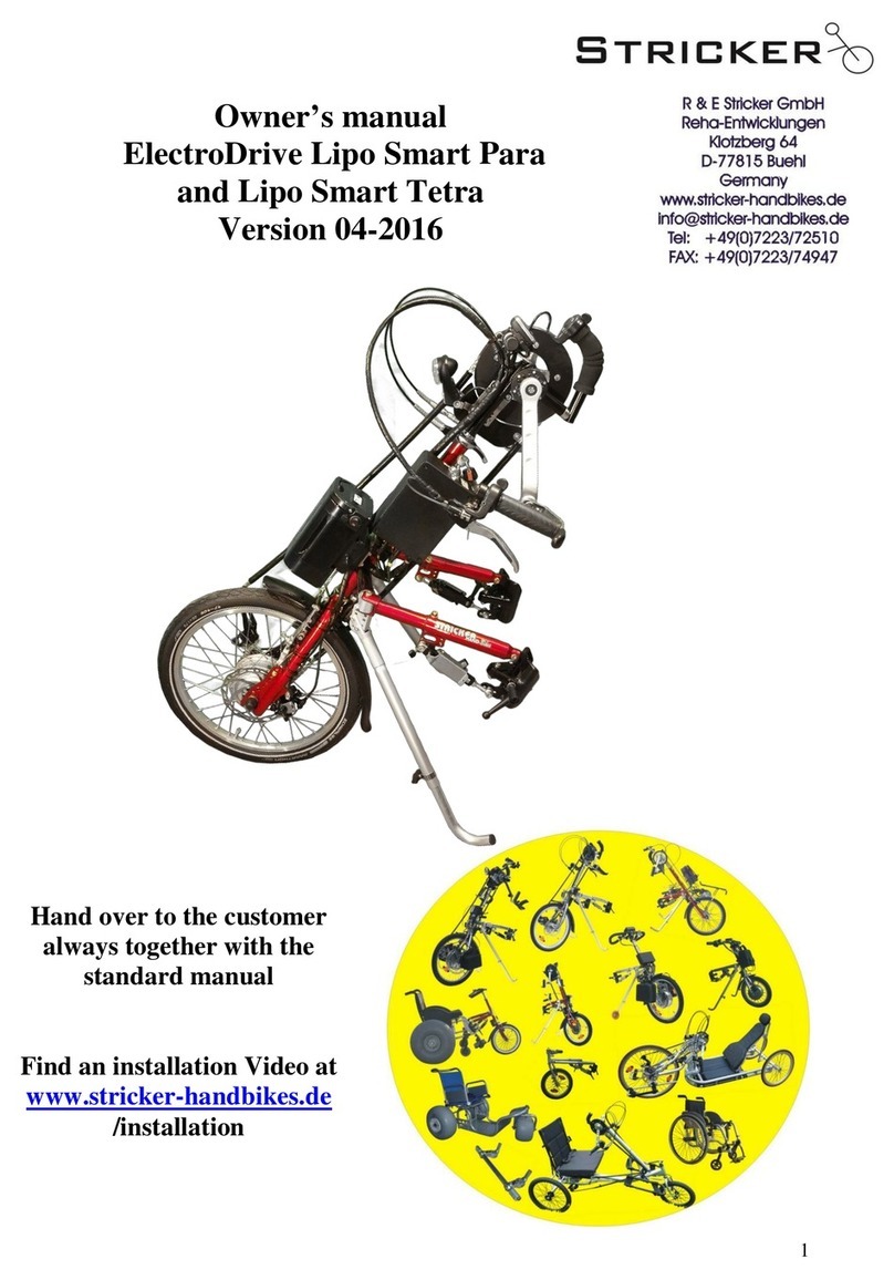
Stricker Lipo Smart Para User manual
Stricker
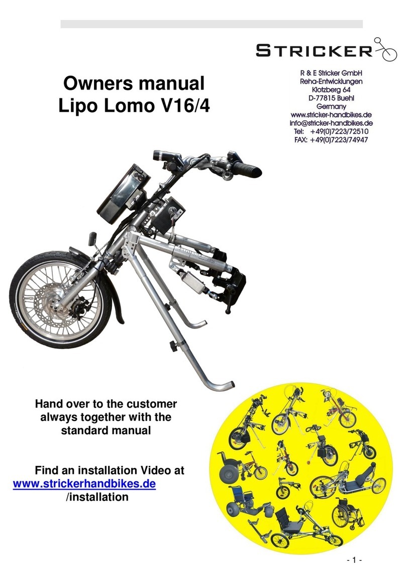
Stricker Lipo Lomo V16/4 User manual
Stricker
Stricker Lipo Smart Series User manual

Stricker
Stricker City User manual
Stricker
Stricker Neodrives Operating instructions

Stricker
Stricker Lipo Smart Series Operating instructions
Stricker
Stricker CITY 7 User manual
