manuals.online logo
Brands
  1. Home
  2. •
  3. Brands
  4. •
  5. STRIKEMASTER
  6. •
  7. Fishing Equipment
  8. •
  9. STRIKEMASTER Solo Magnum User manual

STRIKEMASTER Solo Magnum User manual

OPERATING & PARTS MANUAL
StrikeMaster Corporation
17217 198th Avenue • Big Lake, Minnesota 55309
Phone (763) 263-8999 • Fax (763) 263-8986
www.strik mast r.com
B
u
i
l
d
i
n
g
Q
u
a
l
i
t
y
I
c
e
F
i
s
h
i
n
g
E
q
u
i
p
m
e
n
t
F
o
r
O
v
e
r
6
3
Y
e
a
r
s
ATTENTION:
FOR BEST PERFORMANCE IDLE ENGINE FOR 1-2 MINUTES
BEFORE YOU START DRILLING.
SM09
MAG
MAG
Solo® Germany The registered Solo® trademark is licensed for use in the U.S. to the German company Solo
leinmotoren Gmbh by the U.S. affiliate, Solo incorporated.
Ice Fishing has become one of the fastest growing an most popular winter sports, allowing the ar ent
angler the opportunity to enjoy his or her favorite out oor activity.
When you selecte a StrikeMaster power ice auger, you selecte a pro uct that has gaine a reputation
as the quality lea er since 1946. An , there is no oubt that this year's mo el is the finest ever
pro uce by StrikeMaster Corporation.
Your new StrikeMaster ice auger has all of the most wante features in a power ice auger, to assure
many years of enjoyable ice fishing. Some of these features such as workmanship, engineering
excellence, an epen ability have long been stan ar s at StrikeMaster. Your new power ice auger
boasts many new features while retaining the best features evelope in previous years to enhance
your ice fishing experience an a to your satisfaction in selecting StrikeMaster.
We know that you are anxious to go fishing an use your new power ice auger, but, before you go
fishing, it is important an to your a vantage to spen a few minutes getting acquainte with your new
StrikeMaster power ice auger. There is no better way to acquaint yourself with the pro uct than to rea
the Owners' Manual an Operating Instructions. A few minutes spent stu ying this manual before your
first ice fishing outing will be time well spent.
R cord your Mod l and S rial No.'s imm diat ly aft r purchas (s pg. 10). Also, pl as r turn th
nclos d WARRANTY CARD to validat your limit d warranty.
THIS SYMBOL POINTS OUT IMPORTANT SAFETY INSTRUCTIONS WHICH IF NOT
FOLLOWED COULD ENDANGER THE PERSONAL SAFETY AND/OR PROPERTY OF
YOURSELF AND OTHERS. READ AND FOLLOW ALL INSTRUCTIONS IN THIS MANUAL
AND ANY PROVIDED WITH OR ON THE EQUIPMENT ON WHICH THIS ENGINE IS USED
BEFORE ATTEMPTING TO OPERATE YOUR STRIKEMASTER POWER ICE AUGER.
In the best interest of continue technological progress we reserve the right to change the esign an
configuration of any pro uct without prior notice. For that reason, no claims can be accepte with
reference to text an illustrations in this manual.
TABLE OF CONTENTS
Important Safeguar s 3 Storage 8
Power Hea Components 4 Maintenance 8
Assembly Instructions 5 Warranty Info 9-11
Starting/Operation 5-7 Warranty Car 11
Stopping Engine 7

!

!
This ngin is quipp d with a compr ssion
r l as valv for asi r starting. Pr ss th valv in
b for v ry start to r duc cylind r pr ssur .
(S Pag 7)
ATTENTION

!

!
Packaging and Disposal
Please keep the original packaging in or er to
protect the equipment against transport amage in
case you ever nee to ship or transport it. If the
packaging materials are no longer require then
they must be ispose of properly in accor ance
with applicable local regulations. Car boar
packaging materials are raw materials which can
be recycle or reuse .
At the en of the equipments service life, please
make sure that you ispose of it properly, in
accor ance with the official irectives an
regulations that apply in your area.
B
u
i
l
d
i
n
g
Q
u
a
l
i
t
y
I
c
e
F
i
s
h
i
n
g
E
q
u
i
p
m
e
n
t
F
o
r
O
v
e
r
6
3
Y
e
a
r
s
2
3
IMPORTANT SAFEGUARDS
It is r comm nd d that v ryon who us s this product should r ad th Strik Mast r
OPERATING MANUAL and th ngin OPERATOR'S MANUAL b for op ration in addition to
vi wing th nclos d saf ty DVD.
1. DO NOT use this pro uct for any purpose other than cutting ice fishing holes. Ice augers
are precision cutting tools built for the ice fisherman, an must be properly maintaine
an han le with caution uring both cutting an transporting. When not in use, always
store with bla e guar attache .
2. DO NOT use attachments an parts other than those available from the manufacturer.
3. DO NOT alter this pro uct in any manner; oing so is angerous an voi s all warranties.
4. DO NOT allow chil ren or a ults weighing un er 100 lbs. to operate this equipment.
5. DO NOT allow your bo y, loose clothing, rawstrings, scarves, hats or other materials to
come in contact with the Powerhea , Starter Assembly or Auger (Drill) unit at any time.
6. DO NOT operate un er the influence of rugs or alcohol.
7. DO NOT operate if, upon pulling the starter rope or after rilling holes, the auger ( rill)
unit rotates or if the rope pulls har . DO NOT OPERATE. Have the unit checke by a
qualifie mechanic.
8. DO NOT allow the engine to run or operate while moving or transporting to another
location.
9. DO NOT continue to use this pro uct in the event of mechanical or electrical failure.
10. This pro uct pro uces consi erable cutting force that is felt by the operator. Make sure
your feet are firmly plante an that the han les are hel firmly while operating this pro uct.
11. Always check the operation of the throttle system to ensure the carburetor control is
completely returning to the i le position when the throttle lever is release .
12. Ch ck cutting blad s and aug r shaft scr ws b for and aft r ach us to mak sur th y
ar tight.
13. During operation, the auger unit coul possibly stop. Be prepare at all times to release
the throttle lever.
14. Ev ryon who us s this product should r ad this op rating manual b for op rating
this unit.
15. The cutting bla es on the ice auger are razor sharp. Use extreme care when han ling.
16. The manufacturer recommen s that all StrikeMaster augers be use for ice cutting only.

!

!

!

!

!

!

!

!

!

!

!
Thoroughly r ad th s op rating instructions b for
und rtaking any maint nanc , installation and cl aning st ps.

!

!
1. Recoil (starter) Han le 9. Choke Lever
2. Fuel Cap 10. Transmission
3. Fuel Tank 11. Start/Stop Switch
4. Fuel (FULL) Level 12. Spark Plug Cap
5. Decompression Button 13. Recoil
6. Throttle Lever 14. Muffler Guar
7. Air Filter Cover 15. Muffler
8. Throttle Ro 16. Tufflite Han le System
9
7
5
1
2
3
4
6
8
12
14
16
10
15
11
13
4
5
1
ASSEMBLY

!

!
Car fully r mov blad guard and mak sur blad bolts ar tight.
8mm
bolts an
8mm
close
en
wrench
10mm nut an bolt. Use two 10mm
wrenches above an below bla es to
tighten.
Stamping or bla e i entification must
be legible for bla e to be installe
properly.
2R mov M tric All n wr nch and unscr w th collar bolt from aug r.
The large an small holes from
each component must line up
before installing the collar bolt
3R mov Black plastic cap from driv shaft. Ins rt aug r into driv shaft and install collar bolt.
Collar bolt inserts into the large hole, passes
through the rive shaft an threa s into the
small hole of the metal collar. Make sure bolt is
tight. Some wiggle is normal between the
power hea an auger. Check an tighten often.
OPERATION

!

!
1. Start ngin as xplain d on pag 6 & 7 of this manual. For b st cutting p rformanc , run ngin at
idl for on minut b for drilling.
2. Hol the unit in a vertical position with your right han pushing ownwar to open throttle, an your
left han firmly hol ing the opposite han le.
3. This pro uct pro uces consi erable cutting force that is felt by the operator. Make sure your feet are
firmly plante an that the han les are hel firmly while operating this pro uct.
4. Push the throttle lever ownwar to increase the engine spee . As the engine spee increases the
centrifugal clutch will engage an the auger will begin to rotate.
5. During the operation of cutting, the auger coul possibly stop if it comes in contact with a foreign object
or if it bin s in the hole. Be prepare at all times to release the throttle lever to avoi rotation of the
han le assembly.
6. Stop engine if you notice a ifference in the operating characteristics of this machine.
7. Always stop the engine before any contact with the auger, even when clearing ice blockage.
8. Never touch the muffler. As long as it is still hot there is a risk of burns!
9. The cutting bla es on this auger are razor sharp. Use extreme care when han ling an installing bla es
an bla e guar s.
10. After using this machine, STOP the engine by allowing the engine to return to i le an moving the
switch to the OFF position. If engine fails to stop, move the choke lever to FULL CHOKE position to kill
the engine. If the ignition switch has faile DO NOT OPERATE until the ignition switch has been repaire
by a qualifie mechanic.
11. Always check to make sure the throttle system is moving freely an returning to i le.
12. Turn off this machine when traveling from fishing site to fishing site.
13. Always store auger with bla e guar attache .
Push down and twist to
lin up hol s
Large Holes
Metal Collar
Allen Wrench
Collar Bolt
Plastic Collar
Black Cap
Driv Shaft
LAZER BLADE CHIPPER BLADE
6
STARTING PREPARATIONS

!

!
Ch ck th compl t machin for op rational saf ty
• The stop switch shoul function properly.
• The throttle must have free om of movement an return to the
i le position on its own accor .
• The auger bla es an collar bolt must be tightly secure an in perfect
con ition.
• Ensure the spark plug cap an ignition cable are connecte firmly.
FUELING AND OIL/FUEL RECOMMENDATIONS

!

!
Fu l is highly flammabl . K p away from op n flam s and n v r spill fu l. Do not smok at th op rating
sit or at and n ar th r fu ling sit
• Stop the engine prior to refueling.
• Let the engine cool own before refueling.
• Open the fuel cap slowly to allow any excess pressure in the tank to be re uce without the risk of fuel
spraying out.
• Fuel may contain substances similar to solvents. Wear protective gloves uring filling.
• Avoi breathing in fuel vapor.
• Imme iately clean any spille fuel on the machine.
• Firmly tighten fuel cap.
• Check for fuel leaks. Do not start the machine or work with the machine if there is a fuel leak.
• Store fuel an oil in an approve an correctly labele container.
1Oil
To operate your engine you will nee to use a clean, high-quality, 2-cycle oil mixe with fuel at a ratio
of 40:1 (3.2 fl. oz. to 1 gallon of gas).DO NOT USE SYNTHETIC OIL. DO NOT use a fuel/oil mixture
leaner than 50:1 (2.6 fl. oz. to 1 gallon of gas).
2Fu l
• Use unlea e regular, unlea e premium or non oxygenate premium fuel. Do not use fuel with
less than an octane rating of 87. For peak performance use an unlea e premium fuel.
• Do not use lea e fuel or E85.
• FUEL MUST BE FRESH AND CLEAN. NEVER use fuel left over from last season or fuel that has been
store more than 30 ays. Do not use summer blen fuel; only use winter blen fuel available after
November 1st.
• Unsuitable fuel or eviations in mixing ratio may lea to serious engine amage which is not
covere un er warranty.
7
STARTING YOUR ENGINE
1Turn the ON/OFF switch to ON. Make sure to rea the
switch correctly. Rea this si e of the switch.
2Press the primer bulb (Fig 1 ) 5 to 8 times. You want to see
fuel returning in the fuel line.
3Sli e the choke lever to START (FULL CHOKE).
4Press the ecompression button (Fig 1). Pull the recoil
han le in short quick pulls until the engine fires.
(au ible soun ) NOTE: you will nee to reset the button
after every pull of the recoil rope.
5Once the au ible soun is hear , sli e the choke lever to RUN (NO
CHOKE), an continue step 4 until engine starts. If engine fails to start
repeat steps 3, 4 an 5.
STOP ENGINE. Turn ON/OFF switch to th off position. If ngin fails to
stop slid chok to start (Full Chok ) to stop ngin . DO NOT us again
until r pair d.
STARTING TIPS: As you know, very col temperatures make all engines a
little har er to start. Whenever possible, keeping your machine in a warm
environment will ALWAYS make it easier to start. In extreme col
con itions applying a little throttle as you pull your recoil will help the
starting proce ure.
If the engine fails to start after several attempts, check whether all
a justments escribe above have been correctly carrie out, particularly
that the on/off switch is NOT in the off position. Try starting once again.
The combustion chamber will be floo e , if the engine fails to start.
In that case we recommen you procee as follows:
• Pull the spark plug cap off of the spark plug.
• Remove the spark plug an ry fuel mixture from the electro es.
• Move the throttle lever up to full throttle. Pull the starter han le several
times (with spark plug remove ) to clear the combustion chamber.
• Move the throttle lever own to i ling position, refit the spark plug, the
spark plug cap an plug cover.
Start the engine with the choke lever in run (no choke) position an the
on/off switch in the on position.
Fig 1
Do not r ad
this sid
8
SECURING YOUR AUGER DURING
TRANSPORT
Contaminate air filters cause a re uction in engine
performance an increase fuel consumption with more
pollutants in the exhaust gas. Engines are less likely to start
rea ily with a contaminate air filter. Carry out the following
maintenance jobs regularly:
• Turn the wing screw at the air filter cover counter-clockwise.
• Flip the top of the air filter cover forwar an remove.
• Remove the fabric air filter.
• Clean the area aroun the filter.
Simply tapping the filter is the best cleaning metho . Never
wash or clean the air filter with high compresse air or by
wetting it; never place in an oil bath or cleaning solution.
The air filter is blocke if the engine spee noticeably rops
when the carburetor is correctly a juste .
Un er these circumstances, the filter nee s replacing (part no.
20 48 154).
Low engine spee ue to a blocke air filter must never be
compensate by incorrect carburetor a justments. This woul
cause the engine to overloa , resulting in severe engine
failure.
Engine failure cause by incorrect care is exclu e from our
warranty.
• Insert the new or cleane fabric air filter into the casing.
• Position the air filter li with the lower gui ing pins onto
the housing an push into place.
• Secure the filter cover by turning
the wing screw clockwise.
Ch ck th spark plug r gularly
aft r 50 hours of op ration.
• Press the back tab of the spark
plug cover (16) own an
remove in an upwar s
motion.
• Disconnect the spark plug
cap.
• Unscrew the spark plug
an ry electro es.
The spark plug shoul be
replace after 100 hours of
operation or if the electro es are ba ly
worn.
Do not turn the engine over while the spark plug has been
remove or the spark plug cap has been isconnecte from the
high-tension ignition cable. A spark may cause a fire!
Spark plugs with resistor (thermal value 200) are available in
ifferent bran s un er the following escription:
BOSCH WSR6F CHAMPION RCJ-6Y or comparable
The correct electro e gap is 0.5mm or .019 inch.
Only use spark plugs where the contact nut has been firmly
fitte . Loose connections may pro uce sparks, which can
cause fire. Before restarting the engine, check the high-tension
ignition cable for any amage to it’s insulation an ensure the
cable is connecte securely to the plug cap.
• Insert the spark plug into the cylin er hea an tighten it.
• Push the spark plug cap firmly over the spark plug.
• Position the spark plug cover onto the housing by aligning
it with the gui ing pins, push own an click into place.
With your purchase of a StrikeMaster power auger, you have
acquire one of the worl ’s best precision cutting machines. A
little prevention goes a long way. Whether you transport this
machine in a truck, snowmobile, ATV or sle be sure to secure
it own to prevent amage.
SHUT DOWN & STORAGE
For stops longer than four weeks the following steps shoul
be carrie out:
• Empty an clean the fuel tank at a well-ventilate location.
• Start the engine with an empty fuel tank. Run the engine
until the carburetor is empty an the engine stalls.
Otherwise the carburetor nozzles coul become encruste
with resi ual fuel mixture an make a subsequent start
har er.
• Clean the motor well (particularly the air intake
openings, the cylin er fins, the air filter an the fuel filter
area).
• Preferably, store the equipment in a ry an secure place.
Open flames or similar must not be nearby. Prevent
unauthorize access - particularly by chil ren.
• If stabilize fuel is left in the machine it MUST be run
every 30 ays. Failure to o this can cause the carburetor
an fuel system to gum up.
Mor Information can b found on our w bsit :
www.strik mast r.com
All of us at Strik Mast r
thank you for your busin ss.
Good luck fishing!
MAINTENANCE
Before opening the air
filter, close the choke
to prevent irt from
entering the
carburetor.
Air Filter
Wing
Screw
16
0.5mm or
.019 inch
Solo® Germany The registered Solo® trademark is licensed for
use in the U. S to the German company Solo leinmotoren Gmbh
by the U.S. affiliate, Solo incorporated.
9
LIMITED WARRANTY
WARRANTY
The manufacturer warranties trouble-free quality
an will cover the cost of replacing parts which are
foun to be faulty in material or workmanship within
the prescribe warranty perio after the ate of
purchase. Please note that specific warranty
con itions may vary from country to country. If in
oubt, ask your equipment ven or. He is responsible
for warranty matters. Solo Inc. provi es the initial
purchaser with a 2 year engine warranty.
We hope you will un erstan that we cannot be
liable for amage resulting from the following causes:
• Non-compliance with the operating instructions.
• Neglecting essential maintenance an repair work.
• Damage cause by incorrect carburetor a justment.
• Wear in normal use.
• Obvious overloa by continuously excee ing the
maximum performance limit of the pro uct.
• Using non-authorize tools.
• Use of force, incorrect treatment, misuse an
acci ents.
• Damage from excessive heat ue to irt buil up
aroun the cooling fan housing.
• Attempte a justments an repairs by unqualifie
persons.
• Use of unsuitable spare parts or thir party parts, if
these are the cause of the efect.
• Use of unsuitable or stale fuel.
• Damage cause by using the pro uct in the hire or
rental in ustry.
Normal cleaning, a justments or maintenance work
fall outsi e the warranty provisions.
A service center authorize by the manufacturer
must carry out all warranty work.
PARTS SUBJECT TO WEAR AND TEAR
Various parts are subject to application-specific or
normal wear an must be replace in goo time, when
require . The following parts are subject to normal wear
an are not covere by the manufacturer's warranty:
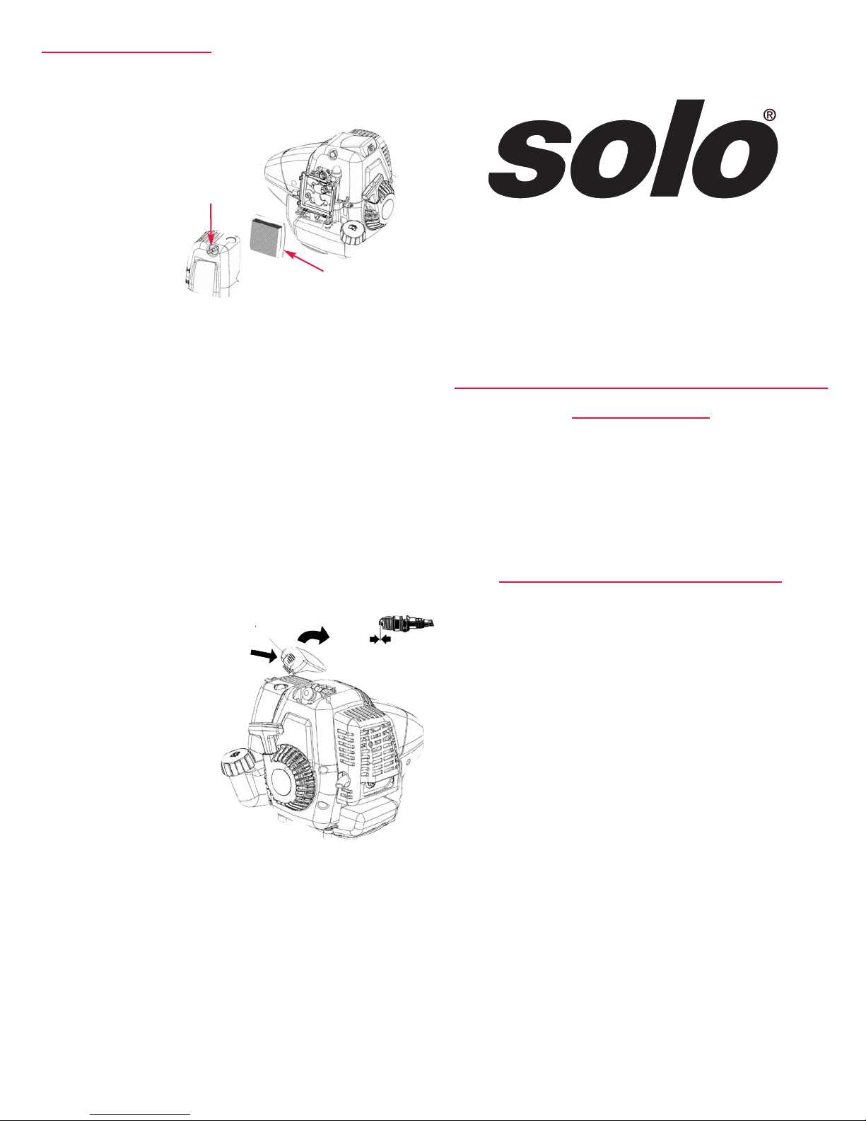
• Air filter
• Fuel filter
• All rubber parts which come into contact with fuel
• Clutch
• Spark plug
• Starter (Recoil)
• Bla es
CE DECLARATION OF CONFORMITY
In accor ance with EG Directives 98/37/EC,
2000/14/EC an 89/336/EEC (amen e by
92/31/EEC), SOLO Kleinmotoren GmbH,
Stuttgarter Strasse 41, D-71069 Sin elfingen,
being solely responsible, states that the pro uct
referre to in this eclaration complies with the
requirements of the Machinery Directive.
Description of pro uct: Ice Auger
(EN ISO 3744, EN ISO 22868)
Applie stan ar s: EN ISO 12100, EN 11806,
ISO 14865, EN ISO 14982
Conformity assessment proce ures
(98/37/EG) Appen ix V
(2000/14/EG) Appen ix V
Serial number, Buil year Type plate
This eclaration of conformity loses its vali ity, if
the equipment is converte or mo ifie without the
manufacturer's consent.
Sin elfingen, 1st January 2006
SOLO Kleinmotoren GmbH Wolfgang Emmerich
Executive Director
FOR USA ONLY
Emissions Control Warranty Statement
The Environmental Protection Agency an Solo are
please to explain the emission control system on your
small non-roa power equipment engine. In the US new
small non- roa engines must be esigne , built, an
equippe to meet the Environmental Protection
Agency's stan ar s. Solo must warrant the emission
control system on your small non- roa engine for the
perio of time liste below provi e there has been no
abuse, neglect, or improper maintenance of your small
non-roa engine.
Your emission control system inclu es parts such as the
carburetor, the ignition system, an the exhaust system.
Where a warrantable con ition exists, Solo will repair
your small non-roa power equipment engine at no cost
to you inclu ing iagnosis, parts, an labor.
Manufacturers Warranty Coverage
Solo's small non-roa power equipment engines are
warrante for a perio of two years. If any emission
control relate part on your engine is efective, the part
will be repaire or replace by Solo.
Contact Information for Authorize Service Center
Locations, Replacement Parts,
Warranty an Technical Information:
Warranty repairs must be complete by a SOLO
Authorize Service Center.
SOLO USA, Inc. 1-800-765-6462
5100 Chestnut Avenue
Newport News, VA 23605
www.solousa.com/support
[email protected]
Model/Type description 137 142 154
Sound power level
Guaranteed sound 112 112 112 dB(A)
Actual sound 111 111 111 dB(A)
Solo® Germany The registered Solo® trademark is licensed for
use in the U.S. to the German company Solo leinmotoren Gmbh
by the U.S. affiliate, Solo incorporated.
10
EMISSION CONTROL INFORMATION
SOLO INCORPORATED 9S9XS 0374SA
EMISSIONS COMPLIANCE PERIOD = NA
Typ 137 36.5 cc 2000692
01000 0 3 / 2 0 0 9
THIS ENGINE COMPLIES WITH US EPA
REGULATIONS FOR WINTER TIME PRODUCT
ONLY 2009 SPAR IGNITION ENGINES
Refer to operatorʼs manual for
maintenance, specifications and adjustments
_________
ENGINE
TYPE
_________
CC
__________
SPEC #
_________
Serial #
__________
DOM
R cord Your S rial Numb r B low
and On Your Warranty Card
S rial Numb r
Locat This D cal on Your Aug r
Sp c #
Engin Typ
DOM (Dat of Mfg.)
cc
Complete Serial #______________________________________________
B
u
i
l
d
i
n
g
Q
u
a
l
i
t
y
I
c
e
F
i
s
h
i
n
g
E
q
u
i
p
m
e
n
t
F
o
r
O
v
e
r
6
3
Y
e
a
r
s
LIMITED WARRANTY
Stri eMaster Corporation, 17217 198th Avenue, Big Lake, Minnesota 55309 provides the following LIMITED
WARRANTY on its products to the purchaser of these products and to any person to whom such products are transferred
during the duration of this warranty.
The warrantor's obligation shall be limited to repairing or
replacing at the above address, any part or parts which
shall within a One Year period hereinafter specified to
be returned to them with transportation prepaid
(customer is responsible for shipping charges to
StrikeMaster) and which upon examination by
Stri eMaster Corporation shows to have been
defective. This warranty shall NOT APPLY IF:
A. The product has been altered, repaired or modified
outside the warrantor's place of business in any way
that would adversely affect its operation.
B. The product has been subjected to misuse or
damage while in the possession of the purchaser
or was operated or used other than in accordance
with the manufacturer's operating instructions.
C. The product failure is attributed to damage which is
the sole responsibility of the user.
The One Year limited warranty period shall commence
with the date the product is sold to the purchaser by the
dealer, or if this date cannot be established, the date the
product was sold by Stri eMaster Corporation to the
distributor or dealer.
THE IMPLIED WARRANTIES OF MERCHANTABILITY
AND FITNESS FOR PARTICULAR PURPOSES ARE
LIMITED TO THE DURATION OF THIS WARRANTY —
One Year — AFTER SAID One Year Stri eMaster
Corporation EXPRESSLY DISCLAIMS ANY
WARRANTY OR MERCHANTABILITY OR FITNESS
FOR ANY PARTICULAR PURPOSE.
Purchase or other acceptance of the product by the
claimant shall be on the condition and agreement that
Stri eMaster Corporation SHALL NOT BE LIABLE FOR
INCIDENTAL OR CONSEQUENTIAL DAMAGES OF
ANY IND.
Some states do not allow limitations on how long an implied warranty lasts or do not allow the exclusion or limitations of incidental
or consequential damages, so the above limitation or exclusions may not apply to you.
To make claim under this warranty write or call (763) 263-8999 directly to "CUSTOMER SERVICE", Stri eMaster Corporation at
the above address for a warranty return authorization. Stri eMaster Corporation will make every effort to repair or replace the
product if found to be defective within the terms of this warranty within 30 days after receipt of the product.
Proof-of-Purchase must accompany product to ensure warrantability.
NOTE: This warranty gives you specific legal rights, and you may also have other rights which vary from State to State.
SEE
SPECIAL
BROCHURE
•Replacement Blades
•Blade Exchange
Service
•Blade Guards
•Auger Extensions
•Gift Ideas
B
u
i
l
d
i
n
g
Q
u
a
l
i
t
y
I
c
e
F
i
s
h
i
n
g
E
q
u
i
p
m
e
n
t
F
o
r
O
v
e
r
6
3
Y
e
a
r
s
763-263-8999
www.strikemaster.com
Fax: 763-263-8986
11
Warranty Registration
This registration card must be returned to StrikeMaster Corporation to validate the
One Year Limited Warranty. Register online at www.strikemaster.com/warranty.html
NAME ________________________________________ DATE PURCHASED ___________________________________
ADDRESS ____________________________________________________________________________________________
CITY____________________________________________ STATE _______________________ ZIP _________________
EMAIL ADDRESS ________________________________________
SERIAL #____________________________
PRODUCT PURCHASED SIZE
■■MORA Hand Auger ___________
■■Lazer Hand Auger ___________
■■Lazer Mag ___________
■■Magnum ___________
PURCHASED SIZE
■■Lazer Pro ___________
■■Electra Lazer 12000 DP ___________
■■Strike-Lite ___________
PURCHASER: ■■Male ■■Female
AGE:________
PURCHASED AS A: ■■Gift ■■Own Use
PURCHASED AT: ■■Local Dealer ■■On-Line
■■Catalog
■■Chain Store
Would you like future new product releases and information from StrikeMaster sent to your email?
Yes / No Email address________________________________________________________
SM09
For Information on our Tun -Up S rvic , pl as visit our w bsit at
www.strik mast r.com
or call 763-263-8999
Strik Mast r Corporation
17217 198th Av nu
Big Lak , Minn sota 55309
PLACE
STAMP
HERE
B
u
i
l
d
i
n
g
Q
u
a
l
i
t
y
I
c
e
F
i
s
h
i
n
g
E
q
u
i
p
m
e
n
t
F
o
r
O
v
e
r
6
3
Y
e
a
r
s
!
Tips%on%starting%your%new%StrikeMaster%Auger%Powered%by%SOLO®!
Before!starting!your!new!StrikeMaster!Auger!we!recommend!these!simple!steps!to!ensure!proper!conditioning!!!
of!your!new!auger!powered!by!the!legendary!German!motor!SOLO®.!
Conditioning%Your%Recoil%
Prior!to!putting!gas!in!your!auger’s!power!head!we!recommend!(in!a!warm!environment),!liberally!spray!WD‐40®!
on!the!recoil!mechanism!as!show!in!the!pictures!below:!
!! ! !
Spray!the!WD‐40®!where!the!recoil!rope!and!the!metal!guide!meet.!!Again,!please!!liberally!spray!the!WD‐40®!to!
ensure!it!lubricates!the!whole!recoil!mechanism.!!This!will!ensure!your!power!head!performs!in!the!conditions!
Ice!fishermen!encounter!during!the!winter.!
How%to%properly%start%the%Solo%Engine:!
1. Turn!ON/OFF!switch!to!ON.!
2. Prime!Engine!5!to!8!times.!
3. Slide!the!choke!lever!to!start.!
4. Press!the!decompression!button!in.!Gently!and!slowly!pull!recoil!rope!until!resistance!is!felt,!then!finish!the!pull!
with!a!short,!quick!pull.!
Note:%it%is%VERY%important%to%find%that%resistance%before%pulling%cord.%That%engages%all%the%
components%properly.%This%decompression%and%resistance%check%must%be%done%before%
every%pull.%
5. Once!you!hear!the!engine!fire,!slide!the!choke!lever!to!run.!Continue!the!pulling!procedure!until!engine!starts.!

This manual suits for next models

2

Other STRIKEMASTER Fishing Equipment manuals

STRIKEMASTER CHIPPER LITE User manual

STRIKEMASTER

STRIKEMASTER CHIPPER LITE User manual

STRIKEMASTER Strike-Lite II User manual

STRIKEMASTER

STRIKEMASTER Strike-Lite II User manual

STRIKEMASTER Honda 35CC LITE User manual

STRIKEMASTER

STRIKEMASTER Honda 35CC LITE User manual

STRIKEMASTER Mora User manual

STRIKEMASTER

STRIKEMASTER Mora User manual

STRIKEMASTER Lithium 40v User manual

STRIKEMASTER

STRIKEMASTER Lithium 40v User manual

STRIKEMASTER 35CC LITE User manual

STRIKEMASTER

STRIKEMASTER 35CC LITE User manual

STRIKEMASTER LITHIUM LAZER User manual

STRIKEMASTER

STRIKEMASTER LITHIUM LAZER User manual

STRIKEMASTER Lithium 24V User manual

STRIKEMASTER

STRIKEMASTER Lithium 24V User manual

STRIKEMASTER BIG VOLT User manual

STRIKEMASTER

STRIKEMASTER BIG VOLT User manual

STRIKEMASTER Lithium 40v User manual

STRIKEMASTER

STRIKEMASTER Lithium 40v User manual

STRIKEMASTER Solo User manual

STRIKEMASTER

STRIKEMASTER Solo User manual

STRIKEMASTER LaserMAG Xpress User manual

STRIKEMASTER

STRIKEMASTER LaserMAG Xpress User manual

STRIKEMASTER LaserMAG Xpress User manual

STRIKEMASTER

STRIKEMASTER LaserMAG Xpress User manual

Popular Fishing Equipment manuals by other brands

ION Alpha Operator's manual

ION

ION Alpha Operator's manual

Varioverse HDC manual

Varioverse

Varioverse HDC manual

Angling Technics Technicat MkII instructions

Angling Technics

Angling Technics Technicat MkII instructions

Innovex Logan Fishing Bumper Sub manual

Innovex

Innovex Logan Fishing Bumper Sub manual

Samus Special Electronics SAMUS - 725G instruction manual

Samus Special Electronics

Samus Special Electronics SAMUS - 725G instruction manual

Crivit 210-5 Instructions for use

Crivit

Crivit 210-5 Instructions for use

Powertiki PT-530 operating instructions

Powertiki

Powertiki PT-530 operating instructions

Browning Maxus MXS1000 user manual

Browning

Browning Maxus MXS1000 user manual

Islander ARMR2 Maintenance manual

Islander

Islander ARMR2 Maintenance manual

Fish Hawk X4D owner's manual

Fish Hawk

Fish Hawk X4D owner's manual

Jenzi JZ-821 instruction manual

Jenzi

Jenzi JZ-821 instruction manual

Eskimo 35000 Operator's manual

Eskimo

Eskimo 35000 Operator's manual

Shimano bantam 100 instruction manual

Shimano

Shimano bantam 100 instruction manual

Shimano Tyrnos 20II Instruction guide

Shimano

Shimano Tyrnos 20II Instruction guide

ORVIS Original Battenkill Disc Reel quick start guide

ORVIS

ORVIS Original Battenkill Disc Reel quick start guide

Bass Pro Shops slab Shooter SBS-10 manual

Bass Pro Shops

Bass Pro Shops slab Shooter SBS-10 manual

Future Carping Godio V60 Product Operation Instruction

Future Carping

Future Carping Godio V60 Product Operation Instruction

Slider HART user guide

Slider

Slider HART user guide

manuals.online logo
manuals.online logoBrands
  • About & Mission
  • Contact us
  • Privacy Policy
  • Terms and Conditions

Copyright 2025 Manuals.Online. All Rights Reserved.