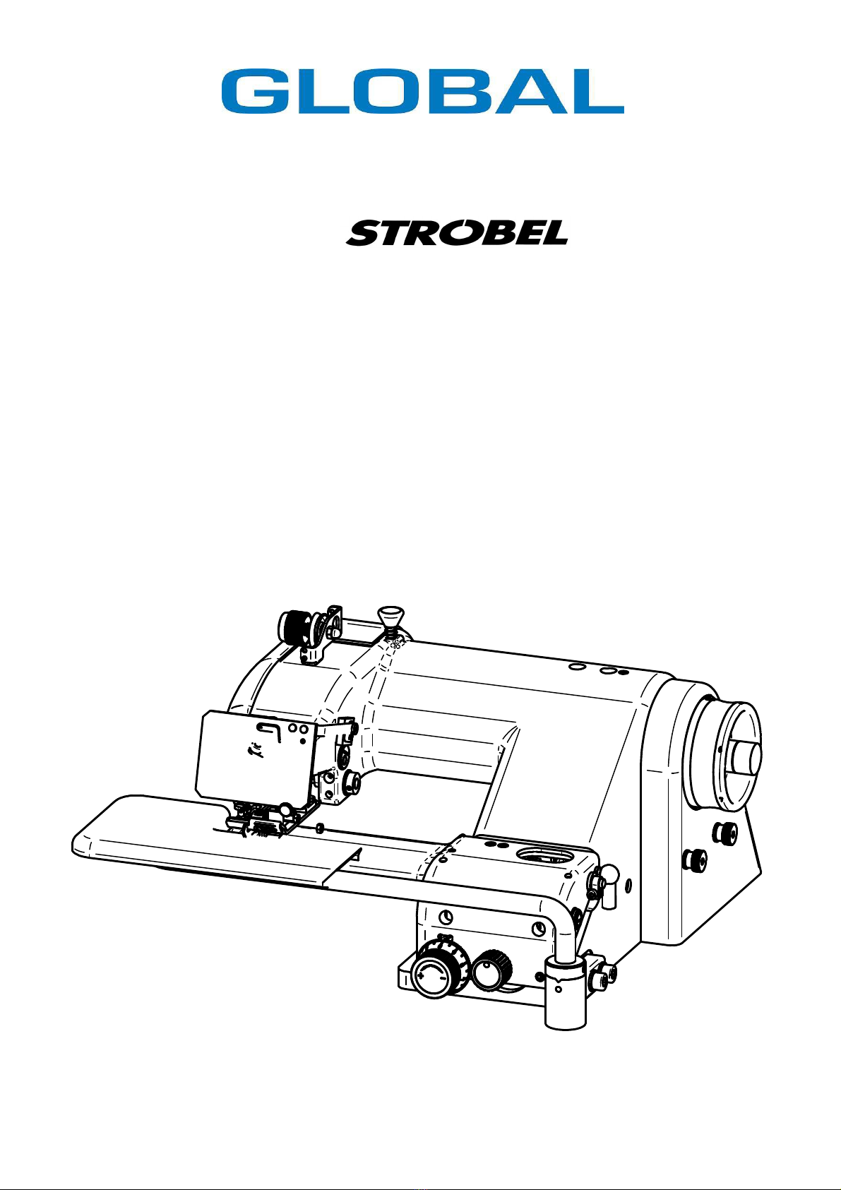
Strobel GLOBAL BM 345 User manual

PRODUCED BY
INDUSTRIAL SEWING MASCHINES
BM 345
Operating In truction

2
From the library of Superior Sewing Machine & Supply LLC - www.supsew.com

3
Operating instructions
BM345
Table of contents
1General notes on safety ...............................................................................................5
2General notes...............................................................................................................7
2.1 Operating instructions ........................................................................................7
2.2 Class designations, machine number and initial basis for descriptions ..............7
2.3 Applications of the machine ...............................................................................7
2.4 Technical data of machine .................................................................................8
3Setup and installation ...................................................................................................9
3.1 Unpacking the machine......................................................................................9
3.2 Setting up the machine.......................................................................................9
3.3 Direction of rotation on machine.......................................................................10
3.4 Motor drive using tooth belts ............................................................................12
3.4.1 Tension of toothed belt (figure 5) ....................................................12
3.4.2 Machine positions ...........................................................................13
4Notes on usage ..........................................................................................................15
4.1 Needles and threads ........................................................................................15
4.2 Inserting the needles ........................................................................................15
4.3 Threading and thread insertion.........................................................................16
4.4 Thread tension .................................................................................................17
4.5 Thread feeder...................................................................................................17
4.6 Stitch depth control...........................................................................................17
4.6.1 Adjusting the stitch depth ...............................................................17
4.7 Cloth retainer....................................................................................................18
4.8 Sewing material transport.................................................................................19
4.8.1 Adjusting the stitch length ...............................................................19
4.8.2 Adjusting the upper transporter .......................................................19
4.9 Interval .............................................................................................................20
4.9.1 Actuating and adjusting the interval ................................................20
4.9.2 Seams with blind stitches ................................................................21
4.10 Sewing problems and troubleshooting .............................................................23
5Servicing the machine ................................................................................................26
5.1 Lubricants.........................................................................................................26
We reserve the right to make design changes.
From the library of Superior Sewing Machine & Supply LLC - www.supsew.com

4
From the library of Superior Sewing Machine & Supply LLC - www.supsew.com

5
1 General notes on safety
Failure to comply with the following safety instructions can lead to bodily
injury or damage to the machine.
1. The machine must only be operated by persons familiar with the relevant
operating instructions and who have been instructed accordingly.
2. Before commissioning also read the notes on safety and the operating
instructions of the sewing drive manufacturer.
3. Only use the machine in the intended manner and never without the
provided guards. Always observe the pertinent safety regulations.
4. Switch off the main switch or pull the power plug for threading, changing
the reels, exchanging sewing tools such as needle, gripper, needle plate,
transport devices, possibly cutter and cutting block, for cleaning and when
leaving the workplace as well as for maintenance. When using
mechanically actuated clutch motors not equipped with actuation locks,
always wait until the motor comes to a standstill.
5. General maintenance tasks may be carried out only by properly trained
persons in accordance with the operating instructions.
6. Repair work, retrofitting and maintenance may be carried out only by
technicians or specially trained personnel.
7. When servicing or repairing pneumatic equipment, the machine must be
disconnected from the pneumatic supply. Exceptions are only allowed for
adjustment work and tests of functionality performed by specially trained
technicians.
8. Only specially qualified technicians may work on the electrical equipment.
9. It is forbidden to work on electrically live components! Exemptions are
covered by the EN50110 (DIN VDE0105) regulations.
10. Any retrofitting or alterations to the machine may only be performed under
strict compliance with all pertinent safety regulations.
11. Only use our approved spare parts when servicing and/or repairing the
machine.
12. It is forbidden to operate the upper component until it is determined that the
entire sewing unit complies with EU provisions.
From the library of Superior Sewing Machine & Supply LLC - www.supsew.com

6
13. Warning instructions given in the operating instructions that pertain to
especially dangerous parts of the machine must be indicated at these
positions using a safety symbol.
Warning instructions given in the operating instructions that pertain to
special injury hazards for operating personnel or technicians must be
indicated at these positions using a safety symbol.
It is essential that you observe and follow these instructions as well as the
generally valid safety regulations.
From the library of Superior Sewing Machine & Supply LLC - www.supsew.com

7
2 General notes
2.1 Operating instructions
Every person in charge of setting up, operating, servicing and repairing the
machine must first read and understand the operating instructions and
particularly the safety instructions before starting up the machine.
2.2 Class designations, machine number and initial basis for
descriptions
The operating side of the machine is the initial basis for left/right descriptions.
The class designation (type) and machine/model numbers are fastened to the
rear of the machine case.
This data is also noted on the front cover page of the operating instructions.
2.3 Applications of the machine
The BM345 is especially suitable for blind-stitch seams on thin to medium thick
materials and knitted goods.
From the library of Superior Sewing Machine & Supply LLC - www.supsew.com

8
2.4 Technical data of machine
Stitch number: Mechanical maximum: 3000 min-1
Recommended nominal stitch number: 2200 min-1
Belt pulley diameter/machine dw 80 mm
V-belt profile 10 x 6 mm
Tooth-belt pulley/machine Z = 38
Tooth-belt profile HTD 5M-9
Stitch length 5–8 mm adjustable
Stitch type Single thread-chain stitch-blind stitch
Interval: 1:2 connectible
Needle system STROBEL 1669 EEO
Needle thickness 60, 70, 80, 90
Needle system optional STROBEL 4669 EEO
Needle thickness 65, 80, 90
Thread (recommended) Polyester, continuously twined
Thread thickness (recommended) 120/2, 200
Stitch type 103
Operating noise:
Avg. SPL at measurement surface for stitch number
n = 2200 min-1: LpAm 71 dB(A)
Noise levels in acc. with DIN 45635-48-1 KL3
From the library of Superior Sewing Machine & Supply LLC - www.supsew.com

9
3 Setup and installation
3.1 Unpacking the machine
BM345 machines are delivered solely as upper components.
The upper component, twine stand and other machine accessories can also be
found in the packaging.
Before removing the packaging material, you must carefully check whether all of
the accessory components have been unpacked.
3.2 Setting up the machine
CAUTION! Injury hazard!
Entanglement hazard for clothing or hair and
Danger of finger injuries!
Never operate the machine without the belt guards for
the upper part and motor.
The upper component must be fastened to the provided rubber plate on the
table top. The belt guard must be installed after inserting the V-belt.
CAUTION! Injury hazard!
Before starting the machine, check that the electrical
specifications given on the type plate of the motor,
particular grid voltage and frequency, are appropriate for
your electric system.
Any anti-rust substances, such as vaseline or similar, must be carefully
removed from the sewing tools before starting up the machine.
From the library of Superior Sewing Machine & Supply LLC - www.supsew.com

10
3.3 Direction of rotation on machine
When facing the handwheel, turn it in a clockwise direction.
Figure 1
Figure 2
From the library of Superior Sewing Machine & Supply LLC - www.supsew.com

11
Figure 3
Needle position (when stopped within and outside of the stitch (figure 4))
(when using a thread trimmer):
Adjust the needle position so that when the machine is at a standstill, the
hook of the thread blade can reliably catch the thread loop above the
gripper without touching it.
In conclusion, check this by manually actuating the thread trimmer.
Figure 4
Notes for sewing drives with more than needle positions:
The needle position given above is suitable for sewing at position 2.
It is very important to set position 1 in accordance with the operating
instructions pertaining to the chosen mode of sewing.
Needle plate
Blade
Gripper
Needle
Presser/plunger
Presser/plunger
Needle plate
Needle
Reference position
Positions_01
Positions_16
From the library of Superior Sewing Machine & Supply LLC - www.supsew.com

12
3.4 Motor drive using tooth belts
3.4.1 Tension of toothed belt (figure 5)
Figure 5
Toothed belt tension_01
From the library of Superior Sewing Machine & Supply LLC - www.supsew.com

13
3.4.2 Machine positions
CAUTION! Injury hazard!
Entanglement hazard for clothing or hair and danger of
finger injuries and needle punctures! When checking the
positions while the machine is turned on, keep your
fingers and hands away from moving parts.
Machine with or without thread trimmer:
The machine requires a needle position and, depending on the sewing mode,
possibly a reference position.
Reference position:
The reference position must be set so that the tip of the needle closes
against the right (inner) edge of the needle slide plate facing towards the
inward stitch.
Needle position when stopped, inside and outside of the stitch (figure 3):
Adjust the needle position so that when the machine is at a standstill, the
hook of the thread blade can reliably catch the thread loop above the
gripper without touching it.
In conclusion, check this by manually actuating the thread trimmer.
Notes for sewing drives with more than needle positions:
The needle position given above is suitable for sewing at position 2.
It is very important to set position 1 in accordance with the operating
instructions pertaining to the chosen mode of sewing.
From the library of Superior Sewing Machine & Supply LLC - www.supsew.com

14
Needle position (when stopped within the stitch):
BM345:
The needle position must be set so that the tip of the needle closes
against the right (inner) edge of the needle slide plate facing towards the
outward stitch.
At the same time, the thread loop lies under tension across the gripper.
The needle position is position 1 at the sewing drive.
Figure 6
Needle
Presser/plunger
Needle plate
Position 1
Positions_03
From the library of Superior Sewing Machine & Supply LLC - www.supsew.com

15
4 Notes on usage
4.1 Needles and threads
The sewing quality can be improved by using the most appropriate needles and
threads for the goods to be produced.
Only use approved STROBEL needle system 1669 EEO or system 4669 EEO.
The machine is delivered with needles of size 80.
Furthermore, needle sizes 60, 65, 70 and 90 are also available.
Note: An intact needle is very important for ensuring good quality stitches.
Bent needle tips, that may only be visible under a magnifying glass,
will lead to poorer sewing results. Replace your needles in time!
We recommend using twined polyester tread of thickness 120/2 or 200. Due to
their high strength and good sliding behaviour at a small thread size, they are
preferable to spun thread.
Guarantee note!
This machine has been configured and broken in using
original Strobel needles.
No guarantees can be given when the machine is
readjusted for the use of different needles.
4.2 Inserting the needles
CAUTION! Injury hazard!
Before replacing needles, switch off the machine and
depress the motor switch pedal to ensure that the
machine is truly at a standstill.
Otherwise there is a danger of finger injuries and needle
punctures.
The bent shape of the needles determines the position of the needle lever. Only
ensure that the needle shank can be pushed into the groove of the needle lever
until it stops and the needle clamping plate is tightly fastened using the screw
((for pos 4) figure 1).
From the library of Superior Sewing Machine & Supply LLC - www.supsew.com

16
4.3 Threading and thread insertion
CAUTION! Injury hazard!
Before threading, switch off the machine and depress the
motor switch pedal to ensure that the machine is truly at
a standstill.
Figure 7 indicates the correct threading using the thread take-up device
Figure 7
From the library of Superior Sewing Machine & Supply LLC - www.supsew.com

17
4.4 Thread tension
Depending on the quality, properties and thickness of the thread as well as the
sewing material, the thread tension is set using the knurled nut ((2) figure 1)
until the desired seam shape is created (figure 8).
4.5 Thread feeder
The thread feeder (8) shown in figure 1 prevents the thread from twisting and
the loop from falling. It also ensures that the loop is properly caught by the
gripper and needle.
The seam shape becomes homogeneous and the edge of the seam free of
tension.
The behaviour of the thread feeder is affected by the thread movement (choice
of eye) and thread tension.
4.6 Stitch depth control
The stitch depth controller makes it possible to adjust the distance between
the upper edge of the presser and the needle radius so that the presser is lifted
or lowered, depending on the thickness of the material to be sewed. This
determines how deep the needle can penetrate into the layer of material
between the presser and cloth retainer. This value is referred to as the stitch
depth.
4.6.1 Adjusting the stitch depth
The stitch depth is set using the control button ((5) figure 1) and is located on
the front side of the machine.
Turn the control button to the left (+) to create a deeper stitch insertion.
Turn the control button to the right (-) to create a more shallow stitch insertion.
From the library of Superior Sewing Machine & Supply LLC - www.supsew.com

18
4.7 Cloth retainer
CAUTION! Injury hazard!
When making adjustments in the needle plate area, there
is an injury hazard for fingers due to accidental actuation
of the pedals!
The needle plate is equipped with a cloth retainer. This retainer holds the
sewing material against the presser to allow needles to insert stitches.
The cloth retainer must be set so that the sewing material cannot move as the
needle inserts stitches.
The correct positioning is important for the quality of the stitch! The pressure
of the cloth retainer against the layers of material or seam edge can be varied
by turning the screw ((1) figure 2). This should be kept as small as possible
to prevent the material from developing tension or becoming marked by the
pressure between the presser and cloth retainer. This is particularly important
with delicate materials such as velvet.
However, the pressure must still be sufficient to ensure that the sewing material
cannot move during the needle insertion.
From the library of Superior Sewing Machine & Supply LLC - www.supsew.com

19
4.8 Sewing material transport
The machine transports the sewing material using a rigid upper transport. The
feed (stitch length) can be adjusted between 5–8 mm in 4 levels. The standard
version of the machine is equipped with a sawtooth transporter.
4.8.1 Adjusting the stitch length
CAUTION!
Switch off the machine and depress the motor switch
pedal to ensure that the machine is truly at a standstill.
Press the stitch setting knob ((1) figure 2) and turn the handwheel until it simply
snaps into place. The configured stitch length corresponds to the number
engraved in the handwheel as it comes to a standstill in the highest position.
Press down the setting knob and move the handwheel forwards until the
desired stitch length noticeably snaps into place.
4.8.2 Adjusting the upper transporter
The transporter can be adjusted in its intrusion depth to the needle plate by
loosening the two fastening screws. If the stitch length is adjusted across
a greater range e.g., from 8 to 5, then the transporter should be readjusted.
Adjustments might also be required when changing to sewing materials that are
thicker or otherwise different in quality.
Here, observe the instructions given in the mechanic's manual.
From the library of Superior Sewing Machine & Supply LLC - www.supsew.com

20
4.9 Interval
The machine is equipped with a connectible interval 1:2.
The interval principle is based on recurrent lowering of the presser to an exactly
configured value (interval stitch depth).
When switched on, the outer layer of material is only stitched every second time.
This usually makes it possible to create a marking-free, elastic seam in
materials that are difficult to process.
4.9.1 Actuating and adjusting the interval
The interval stroke (= lowering of presser) defines the stitch depth during the
“interval stitch”.
To switch on the interval for a correctly configured stitch depth, screw in the
control knob ((6) figure 1) until the required interval stroke is achieved.
To adjust the depth of the interval stitch to the thickness of the sewing material
being processed, the interval stroke can also be adjusted continuously. This is
particularly advantageous with very thin sewing material because each
reduction of the stroke helps to reduce “air stitches”.
More stroke means a more shallow stitch and vice versa.
From the library of Superior Sewing Machine & Supply LLC - www.supsew.com
Table of contents
Other Strobel Sewing Machine manuals

Strobel
Strobel 4 User manual

Strobel
Strobel 170-22D User manual

Strobel
Strobel 327D User manual

Strobel
Strobel VEB100-6 4 User manual

Strobel
Strobel KA-ED Operating instructions

Strobel
Strobel VEB 200-1 User manual

Strobel
Strobel 325-40D-TP User manual

Strobel
Strobel 58-4 User manual

Strobel
Strobel 325-40D-TP User manual

Strobel
Strobel 58 Series User manual

Strobel
Strobel 141-30 User manual

Strobel
Strobel VEB100-6 2 User manual

Strobel
Strobel 218D-TP-R User manual

Strobel
Strobel 218D-TP-R User manual

Strobel
Strobel VEB100-6 User manual

Strobel
Strobel 141-23 User manual

Strobel
Strobel 560-21 User manual

Strobel
Strobel 310D-R User manual

Strobel
Strobel 170-22D User manual

Strobel
Strobel 141-23EV User manual