Stromberg Carlson Products CL-36 User manual
phone: 231-947-8600
www.strombergcarlson.com
INS-CL36
12.14.16 For installation video and parts breakdown, see www.strombergcarlson.com or call 231-947-8600 x108
Extend-A-Line
MODEL # CL-36, CL-27 & CL-12
Thank you for purchasing the Extend-A-Line by Stromberg Carlson Products, Inc.
Please read all directions prior to installation. The Extend-A-Line clothes line is designed to support 10 lbs per arm, 60 lbs maximum load
when evenly spaced. Clothes line must be removed prior to travel, or if you are climbing up/down your ladder, as the housing will not
withstand the pressure of being climbed on. Fold arms into the storage position (shown below) and secure with hook and loop straps
prior to installation/removal and when not in use. The Extend-A-Line is designed to be mounted to 1” or 1 ½” exterior ladders with 9 5/8”
- 10 1/8” spacing between upright tubing (variable based on ladder tubing diameter). Prior to installation of your clothes line, inspect arm
bases to ensure they are securely contained in the receiving holes of the housing. Please take into consideration inclement weather
conditions and remove/store to increase the life of your product. Make sure to fasten items appropriately to clothes line to prevent loss
of clothing.
Carton Contents: (1) plastic clothes line housing assembly with (6) chrome arms and (1) aluminum mounting bracket (designed for
alternate mounting method). Fully exploded parts diagram shown on reverse side. Large bag with twist fastener provided for storage
when not in use/not mounted to your unit.
Ladder mounting method:
Ensure there is ample clearance behind your unit’s ladder to allow the arms to swivel 180° without interference.
Identify a comfortable working height, where you can hang items without them touching the ground.
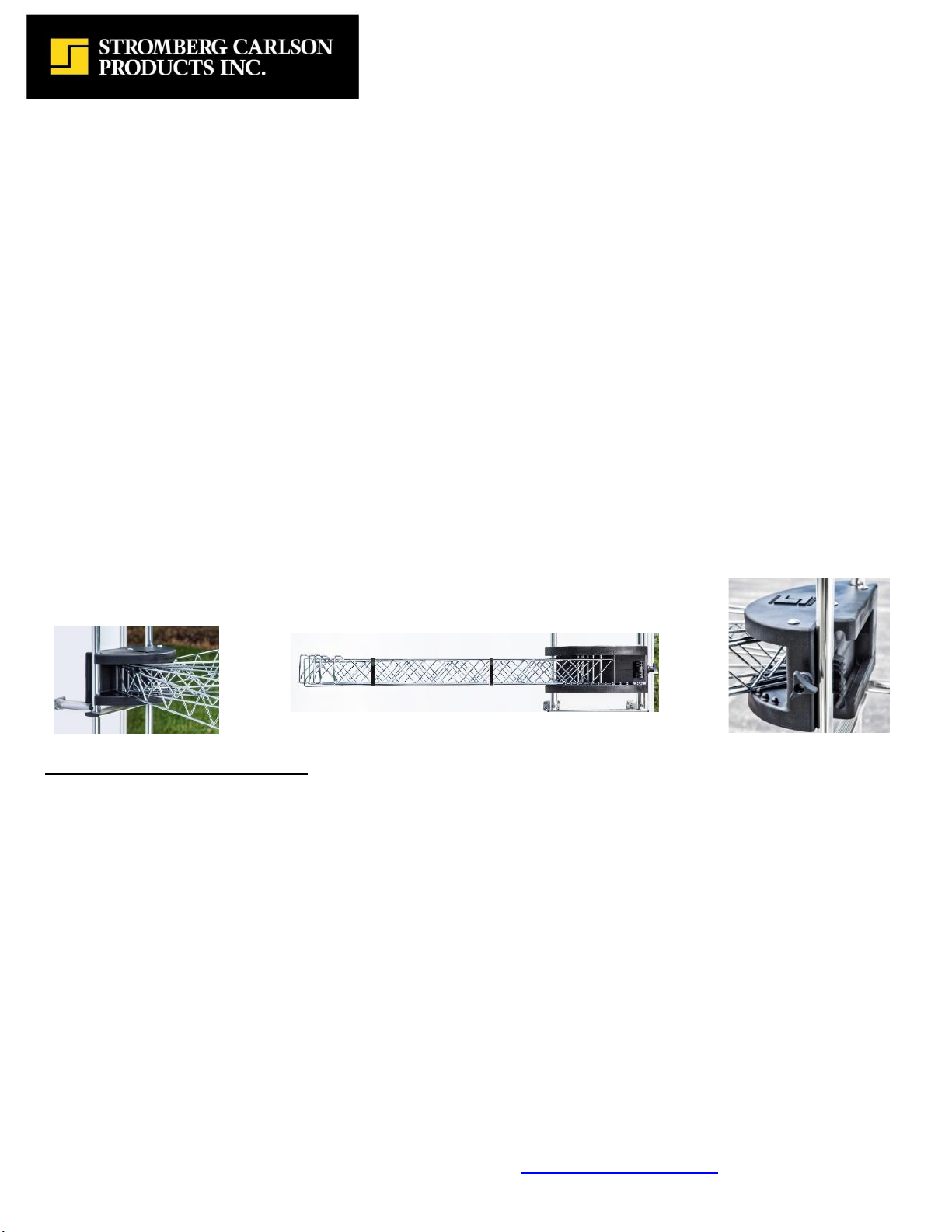
Make sure the adjustment knob is loosened and the clamshell grip is fully open.
With your clothes line in the storage position (shown below), place the non-clamshell side of the housing around your ladder
tubing and rotate it flush against both ladder tubes. Bottom of housing should be resting on a ladder tread.
Tighten adjustment knob until clamshell is tight around the ladder tubing (shown to the right).
See picture below for example of properly installed Extend-A-Line.
Unfasten your clothes line arms and spread to appropriate positions.
Aluminum bracket mounting method:
Remove aluminum mounting bracket from the sleeve on the back of the Extend-A-Line housing.
Identify your mounting surface, being sure to locate structural backing to screw into. Wood or square tube framing is
recommended.
If there is no structural backing, it is recommended you through bolt with appropriate bolts, washers and nuts (not provided).
Do not mount with wall anchors, refer to your camper’s manufacturer if you question your backing.
Align your mounting bracket horizontally on your mounting surface. If the holes pre-drilled in your mounting plate (designed for
use with the bumper mount kit) do not line up with your structural backing, you will need to drill additional holes in your
mounting plate.
Mark center lines of holes you have identified as appropriate for mounting, then set your bracket aside.
Drill pilot holes in your mounting surface, into the structural backing.
Apply a small amount of caulk to the pilot holes to prevent moisture from seeping into your unit/wall.
Before the caulk dries, align your bracket with the appropriate mounting holes and attach the bracket to your mounting surface
with appropriate fasteners (determined based on actual mounting location).
With your clothes line in the storage position, slide it onto the aluminum mounting bracket.
Once your clothes line is securely in place, unfasten your clothes line arms and spread to appropriate positions.
* Additional mounting brackets may be purchased by calling Stromberg Carlson Products directly. Reference part #5806-CL.
** Alternate mounting locations: laundry areas, pool/hot tub areas, basements, garages, etc.
Storage Position Clamshell
Mount
Properly Installed Housing
Clamshell Mount

phone: 231-947-8600
www.strombergcarlson.com
INS-CL36
12.14.16 For installation video and parts breakdown, see www.strombergcarlson.com or call 231-947-8600 x108
Extend-A-Line Bumper Mount & Hitch Mount
MODEL # CL-01 & CL-02
Thank you for purchasing the Extend-A-Line Bumper Mount by Stromberg Carlson Products, Inc.
Please read all directions prior to installation. The Extend-A-Line Bumper Mount is designed to attach to 4” square bumpers and 6” x 2”
A-frames. It is intended to provide alternate mounting locations for the Stromberg Carlson Products Extend-A-Line. When installed
properly, the Extend-A-Line Bumper Mount will carry the full load capacity of the CL-36/CL-27/CL-12 (60 lbs evenly spaced). Please note
the Extend-A-Line must be removed prior to travel.
CL-01 Assembly Instructions
1. Identify all carton contents are present
2. Locate installation location on bumper/A-frame, providing ample
clearance for the CL-36/CL-27/CL-12 arms to fan out fully
3. Remove the aluminum mounting bracket from the back of the housing
on your CL-36/CL-27/CL-12 (not provided) and attach it to the top of your
bumper mount tube (5850-CL). Slide the remaining 2-1/4” long bolts
(FST-1886) through the front side of the mounting bracket and secure
with the flat washers (FST-1865) and lock nuts (FST-1870) on the back
side of the bumper mount tube (5850-CL)
4. Determine which holes on the bumper mount tube (5850-CL) will
accommodate your application (the end of the tube with three holes will
mount to your bumper/A-frame, the end with 2 holes will mount to the
CL-36/CL-27/CL-12 bracket)
5. Slide each 6-1/2” long bolt (FST-1898) through the mounting hole
locations you have identified on the bumper mount tube (5850-CL). One bolt will be across the top side of your bumper/A-frame and
one bolt will be across the bottom side of your bumper/A-frame
6. From the back side of your bumper/A-frame, slide the back plate (7605-117) over the 6-1/2” long bolts (FST-1898), with the flat side
resting against the bumper/A-frame
7. Place (1) flat washer (FST-1865) and (1) lock nut (FST-1870) on the end of each bolt and tighten until secure
8. Insert the end cap plugs (CP-1045) into each end of the bumper mount tube (5850-CL)
9. Plug unused mounting holes on the bottom of the tube with the round locking hole plugs (CP-1030)
10. Slide your CL-36/CL-27/CL-12 (not provided) onto the mounting bracket and enjoy!
CL-02 Assembly Instructions
1. Identify all carton contents are present (including CL-01 components)
2. Remove CL-01 Bumper Mount Tube (5850-CL) and mounting bracket from bumper/A-frame
3. Take both Receiver Tube Angle Brackets (5851-CL) and mount onto holes
located on the sides of the Receiver Tube (5853-CL) with the 2 ¾” Bolt (FST-
2428) and the ½”Lock Nut (FST-2482) as shown in Fig 1
4. Take both 2 ¼” Bolts (FST-1886) and slide into holes located on the Receiver
Tube Angle Bracket that was installed onto the Receiver Tube in Step 3. Slide
these bolts through two of the holes on the bottom of the CL-01 Bumper
Mount Tube (5850-CL)
5. Put one 5/16”Flat Washer (FST-1865) and one 5/16”Lock Washer (FST-1860)
onto each 5/16”Bolt (FST-1886) as shown in Fig 2
6. Screw 5/16”Hex Nuts (FST-1870) into the back of the CL-01 until tight
7. Insert Receiver Tube assembly into 2” hitch and secure.
8. Slide CL-36/CL-27/CL-12 onto mounting bracket and enjoy!
Fig 1 Fig 2
#
ITEM #
DESCRIPTION
QTY
1
7605-117
Back Plate –Lower Mount
1
2
CP-1030
Round Locking Hole Plug
2
3
FST-1898
5/16 - 18 x 6-1/2” Bolt
2
4
FST-1865
5/16 Flat Washer
4
5
FST-1886
5/16 - 18 x 2-1/4” Bolt
2
6
FST-1870
5/16 - 18 Lock Nut
4
7
5850-CL
Bumper Mount Tube
1
CP-1045
1-1/2” Square End Caps (not pictured)
2
#
ITEM #
DESCRIPTION
QTY
1
FST-2428
½”-13 x 2 ¾” Bolt
1
2
FST-1865
5/16”Flat Washer
2
3
FST-2482
½”Lock Nut
1
4
FST-1870
5/16”Hex Nut
2
5
FST-1886
5/16”-18 x 2 ¼” Bolt
2
6
5853-CL
Receiver Tube
1
7
5851-CL
Receiver Tube Angle Bracket
2
FST-1860
5/16 Lock Washer (not pictured)
2
This manual suits for next models
2
Table of contents
Popular Dryer manuals by other brands


GE
GE DSKS333E Owner's manual and installation instructions

American Specialities, Inc.
American Specialities, Inc. 0199 manual

Whirlpool
Whirlpool LE7685XP Use & care guide

Siemens
Siemens WT47XKH1GC Installation and operating instructions

Maytag
Maytag MDG16MN Specifications

Frigidaire
Frigidaire GLER341A Factory parts catalog

Frigidaire
Frigidaire GLGR642A Factory parts catalog

Children's Hand Hygiene Company
Children's Hand Hygiene Company Puff the Magic Dryer quick guide

TSM
TSM WILLMOP 35 Original instructions

Aerial
Aerial WT 230 instruction manual

Bosch
Bosch WTG86400IN Installation and operating instructions

Kenmore
Kenmore 60812 instructions