Strong Racks PowerRax Double Bike Lift User manual

1
PowerRax Double Bike Lift
Model: Motorized and Manual

Table of Contents
2
Table of Contents
PAGES
Installation Support
3
Safety Information
4-5
Required Tools
6
Hardware Kit Contents
7
Part List
8
Steps
1 & 2 9
Step 3
10-12
Step
413
Step 5
14
Step 6
15
Step 7
16-17
Step
818
Step
919
Step 10
20
Step 11
21-24
Step
12 25-26
Appendix I
–Understanding Your Ceiling Support
System
27
Appendix
II –Storage Locator Worksheet 28
Appendix III
–Proper Mounting 29
Appendix
IV –Installation Help 30

3
Please Do Not Return This Product To The Store!
1-877-717-RACK (7225)
info@strongracks.com
If there are any missing or damaged parts, please contact us immediately for
replacement. In some cases, a new part can be shipped to you within 1-3 days.
Our quality control members hand check every box prior to shipment. We take this very
seriously and want you completely satisfied.
If you find that installation of our products might be a little more technical than you
anticipated, then we can simply guide you to a qualified installer and arrange for the
installation. Our vast installation support network allows us to offer you the extra
support you might need with busy schedules.
Please review our list of dealers at www.strongracks.com or contact us for help. Refer
to Appendix IV for additional installation help.
Installation
Support

4
STOP: Ensure that you understand your
ceiling support structure prior to
installing.
Ensure that you know your load prior to
loading items on your ceiling storage
system.
Our products are designed for installation into properly constructed
wood ceiling joists, TGI’s or floor joists. Do not install into metal
studs or ceiling concrete floors. We do not warranty or make any
claim to the construction of your home. If you have any questions
about your homes construction, check with your local builder. If
you are not comfortable with installing this product, call one of
our authorized dealers for support.
Do not use this unit for any other purpose than what was intended.
Proper operation and usage lies with the user.
Safety Information

5
Safety Information
You must read this entire manual before attempting to install this product. We also suggest you
visit www.strongracks.com to review our installation video. If you have any additional
questions or need to speak with an installation professional, do not hesitate to call us directly.
We will provide timely responses to your questions.
1-877-717-RACK (7225) Monday - Friday 9am-5pm Arizona Time
We have hundreds of qualified dealers throughout North America. Visit www.strongracks.com
to contact your local installer.
!!
Warning Warning
!!
Warning Warning
Electrical , Plumbing or Gas Lines
May Be In The Ceiling or Walls
Be Aware of Falling Items or
Personal Fall Hazard
Prior to drilling, you must identify where
your electrical, plumbing and gas lines
are inside your walls or ceilings. Failure
to do so may result in damage or serious
injury. Contact a professional to locate.
Be aware when climbing a ladder. Do
not have your hands full when climbing.
Do not lean out away from the ladder to
load or install the system. Do not
overreach or overextend from ladder.
Ceiling Joist, Truss and Wall Stud
Overloading Potential
This system can be installed into 2 or 4
Ceiling Joists. We recommend that you
install into 4. You can also install the
system into the wall studs. If you install
into 2 joists, do not install another unit
into the same joists.
System May Be A Personal
Injury Hazard
Failure to read and follow these
installation instructions, per the
manufacturer’s guidelines, may result in
serious injury or death. If you are
uncomfortable installing yourself, please
contact us or visit our website to
identify an installer of our products.
6
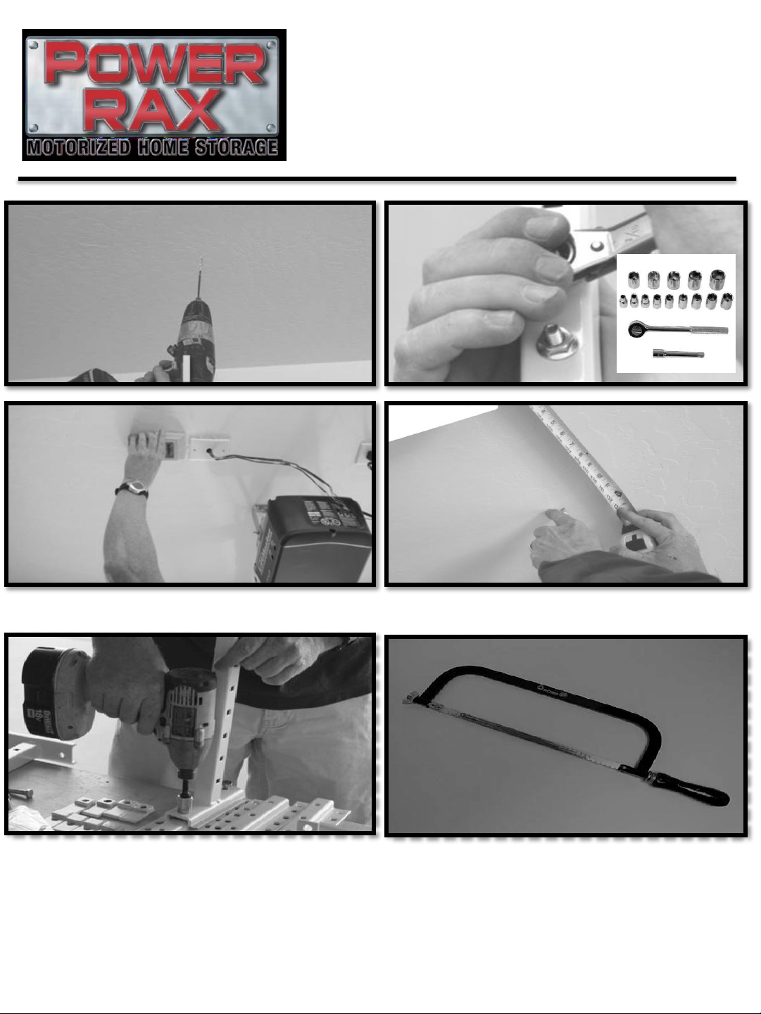
Required Tools
Electric Drill with 1/8” bit
Stud
Finder
We recommend that you use the Storage Locator Worksheet (Appendix II),
to note where you would like to install our products. You can also draw out
the position / direction of your ceiling trusses, as it relates to our systems.
Keeping good notes will ensure proper installation and support future
installations.
Tape
Measure
and Pencil
Standard
Socket
Set
Metal Hack Saw
Electric Hammer Drill
Optional Tools
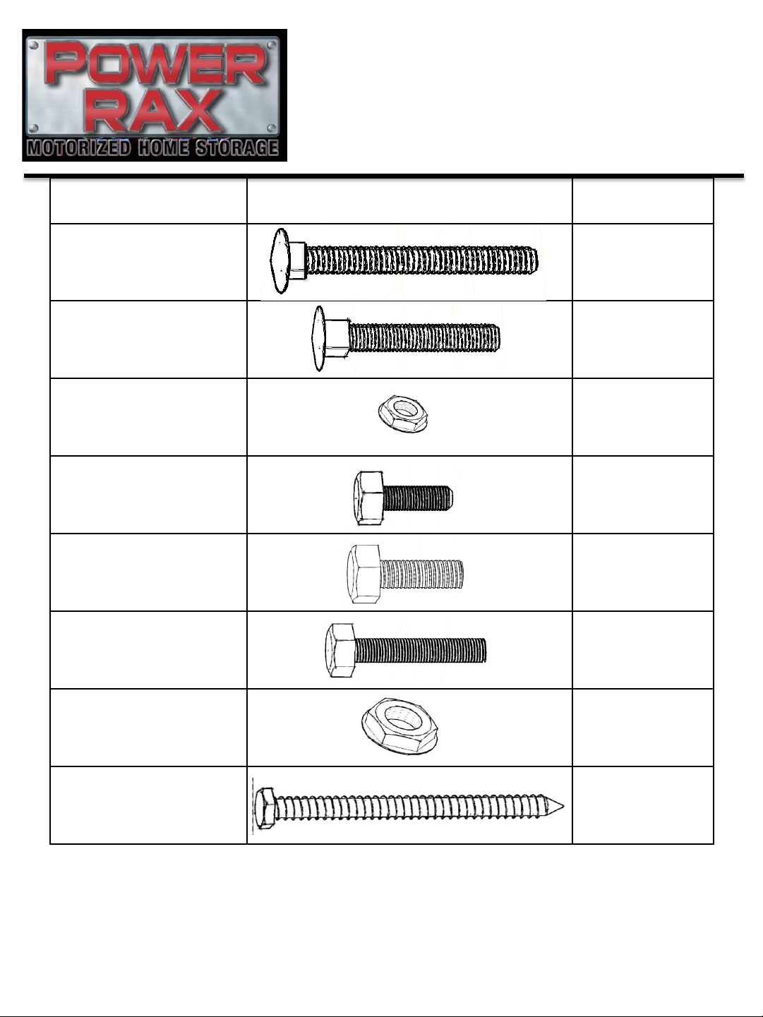
Hardware Kit Contents
7
Letter and Name
Picture Quantity
Large Carriage
Bolt [2 ½”] X8
Small Carriage
Bolt [1 ½”] X8
Small Nut x16
Small Bolt [¾”] x4
Medium Bolt
[1 ½”] x8
Large Bolt
[1 ¾”] x4
Large Nut x12
3” Lag Screw x8
Note: Extra hardware may be included in kit.

Part # and Name Picture
Quantity
Mounting Track x2
Down Tube x2
Inner Tube x2
Upper Swing-Arm
Tube x2
Swing-Arm
Connection Tube x2
Lower Swing-Arm
Tube x2
Support Tube x4
Bike Hook x4
Pick Point or x1
Mounting Tracks
w/additional holes
(motorized version only*)
x2
8
Part List

1
Determine your ceiling support system. To understand your truss direction, spacing or
placement, you may need to enter your attic. You may also need to consult your builder or a
licensed contractor. As an additional resource, refer to Appendix I. Tip: The direction of your
ceiling outlets will indicate the direction of your trusses, just as the location of your garage door
support will indicate the location and spacing of your trusses.
2
Determine what section of the garage will house your new Bike Lift. Make sure there are no
obstructions within the designated space (i.e., lights, attic door, sprinklers, etc.). If you have
cabinets in your garage, make sure there is adequate clearance for doors to open.
9

10
You may secure your
Mounting Track into a
single truss by
inserting the lag bolts
through the center
holes.
You may secure your
Mounting Track into two
separate trusses: from the
center of the mounting
track measure
approximately 1 ¼” in
each direction to pinpoint
the appropriate drilling
locations.
Four lag screws secure
each mounting track into
two trusses
Two lag screws
secure each
mounting track
onto a single
truss
OR
Follow
Instructions 3A 3B
There are two methods to install the mounting tracks.
Determine which is needed for your placement before
proceeding.
Follow
Instructions

3A
When installing down the center of the Mounting Track: find the center of the truss (for more in
depth information please see Appendix III), drill a pilot hole, secure the Mounting Track with one
Lag Screw firmly (Do not over tighten). Square the Mounting track by measuring from a fixed
point to your first Lag Screw, carry that measurement to your next Lag Screw evenly and securely
tighten both.
11
Hardware Required:
x4
Ensure the lag screw is in
the center of the truss.
Refer to Appendix III for
additional information
regarding proper
mounting.
No!
Yes!
If your truss spacing is 24”
center to center, you will
attach your Mounting Tracks
24” apart.
When installing down the center of a truss:
If your truss spacing is 16” center to
center, you will attach your Mounting
Tracks to two trusses measuring 32”
apart (skipping the center truss).
24”
32”

3B
When installing the Mounting Track into separate trusses: find the center of the truss (for more
in depth information please see Appendix III), drill a pilot hole, secure the Mounting Track with
one Lag Screw firmly (Do not over tighten). Square the Mounting track by measuring from a
fixed point to your first Lag Screw, carry that measurement to your next Lag Screw evenly and
securely tighten both. Four Lag screws per Mounting track should be used.
12
Hardware Required:
x8
Ensure the lag screw is in
the center of the truss.
Refer to Appendix III for
additional information
regarding proper
mounting.
No!
Yes!
24”
Mounting Tracks should be installed 24” Center to Center.
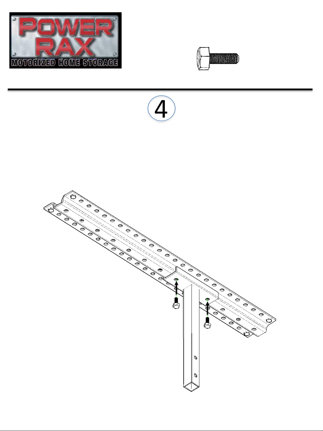
4
13
Hardware Required:
x4
Secure each of the Down Tubes to the Mounting track using two
Small Bolts per tube. Ensure the Down Tubes are in the same
position on the Mounting Track by counting the holes to keep
them in line with one another. You may choose any location on
the track that suits your needs.
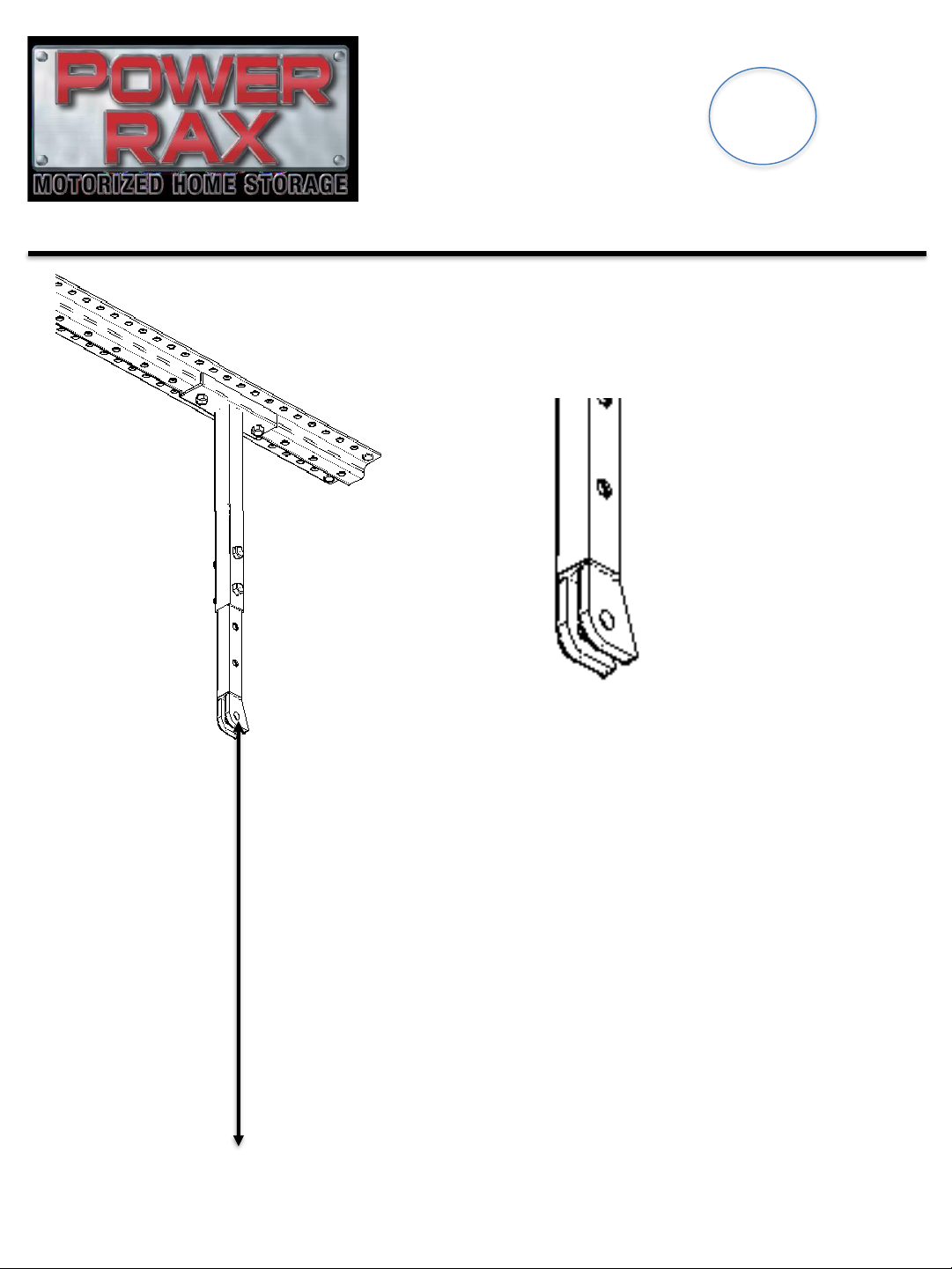
Measure from the center of the hole
in the backstop to the floor. This
measurement will be used to
determine the overall length of the
swing-arm tubes. The full swing-arm
consists of the upper, connector, and
lower swing-arm tubes.
14
Floor
5
Swing
Arm

6
To assemble the Swing-Arm: slide the connector tube into the Upper Swing-arm tube and slide
the Lower Swing-arm tube onto the connector tube. Using your measurement from the
previous page: lay your tape measure from the hole on the Upper Swing-arm tube along the side
of the tubes and adjust until you are 1”to 3”less than your measurement (this will ensure when
the arm swings down it will have a gap from the floor).
15
For maximum extension, the connector tube should have 6 holes inside each of the upper and lower
swing-arm tubes –this should never be exceeded.
Before
After
1” to 3”
for gap
Upper/Lower Connector
1 2 3 4 5 6

7
Continued:
Once the length has been determined: Secure the Upper Swing-Arm
Tube with the Swing-Arm Connection Tube using 2 Small Carriage Bolts
and 2 Small Nuts, Secure the Lower Swing-Arm Tube with the Swing-Arm
Connection Tube using 2 Small Carriage Bolts and 2 Small Nuts.
Repeat for the other Swing-Arm, ensuring the same length and hole
usage.
16
Hardware Required:
x8
x8
Connector
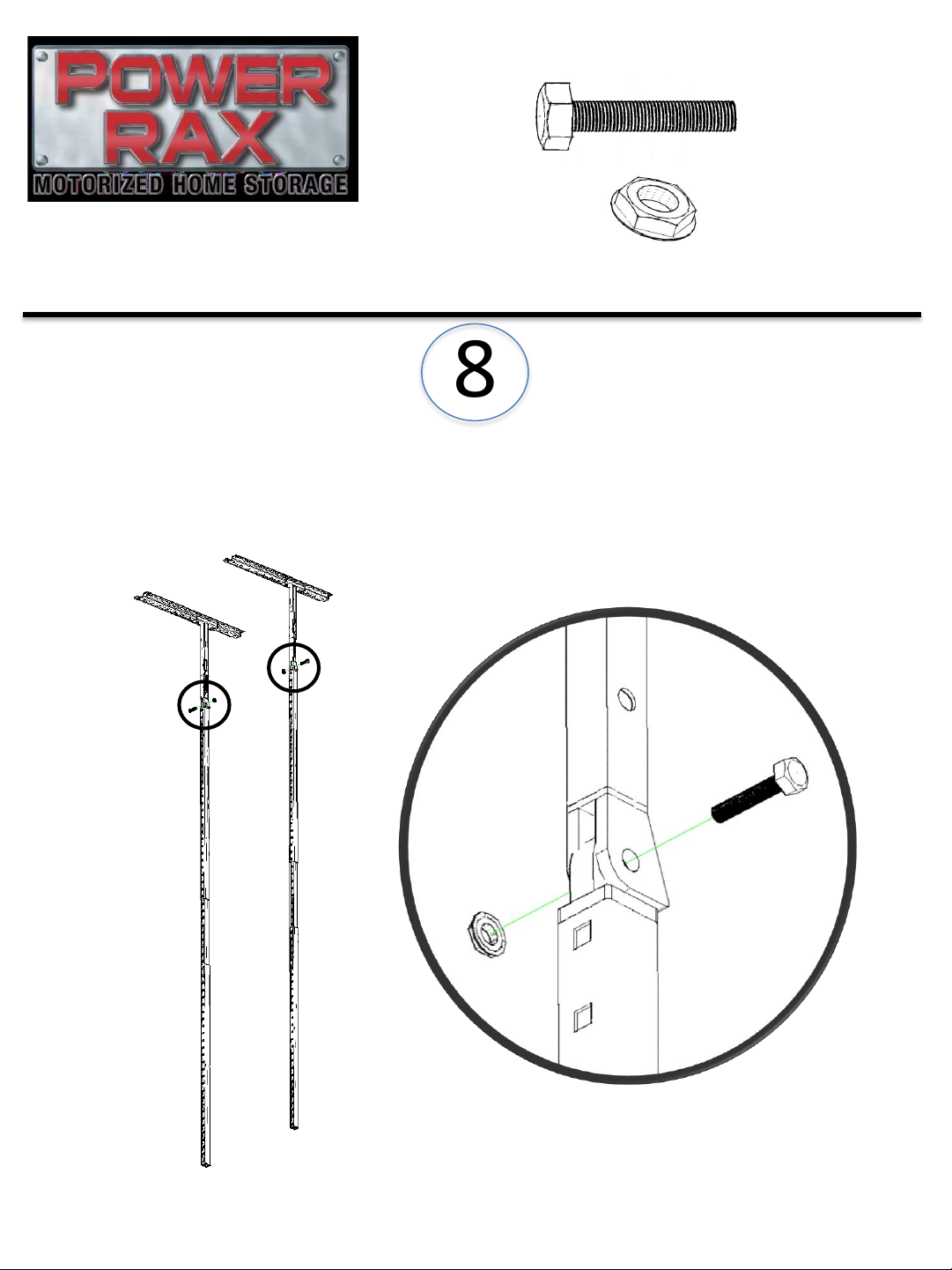
8
Attach both Swing-Arm assemblies to the Inner tubes
using 1 Large Bolt and 1 Large Nut per tube.
17
Hardware Required:
x2
x2

9
Attach one support tube using the bottom hole of each
Swing assembly. Secure using 2 Large Carriage Bolts and
2 Small Nuts.
18
Hardware Required:
x2
x2

10
Attach one support tube using the top hole of each Swing
assembly (just below the pivot point). Secure using 2
Large Carriage Bolts and 2 Small Nuts.
19
Hardware Required:
x2
x2
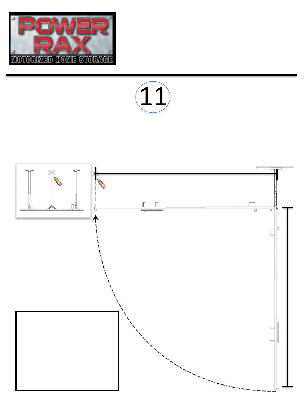
11
Option 1: Flex the system until it is level. Directly above
the pick point, in the center of the unit, place a pencil
mark on the ceiling. This mark is going to be
representative of your motor hook.
20
X
X
End View Side View
A
B
Option 2: Measure
the length point “A” to
point “B” and use that
measurement to
create your pencil
mark on the ceiling
Table of contents


