HMS-VILGO LIFTY 4 User manual
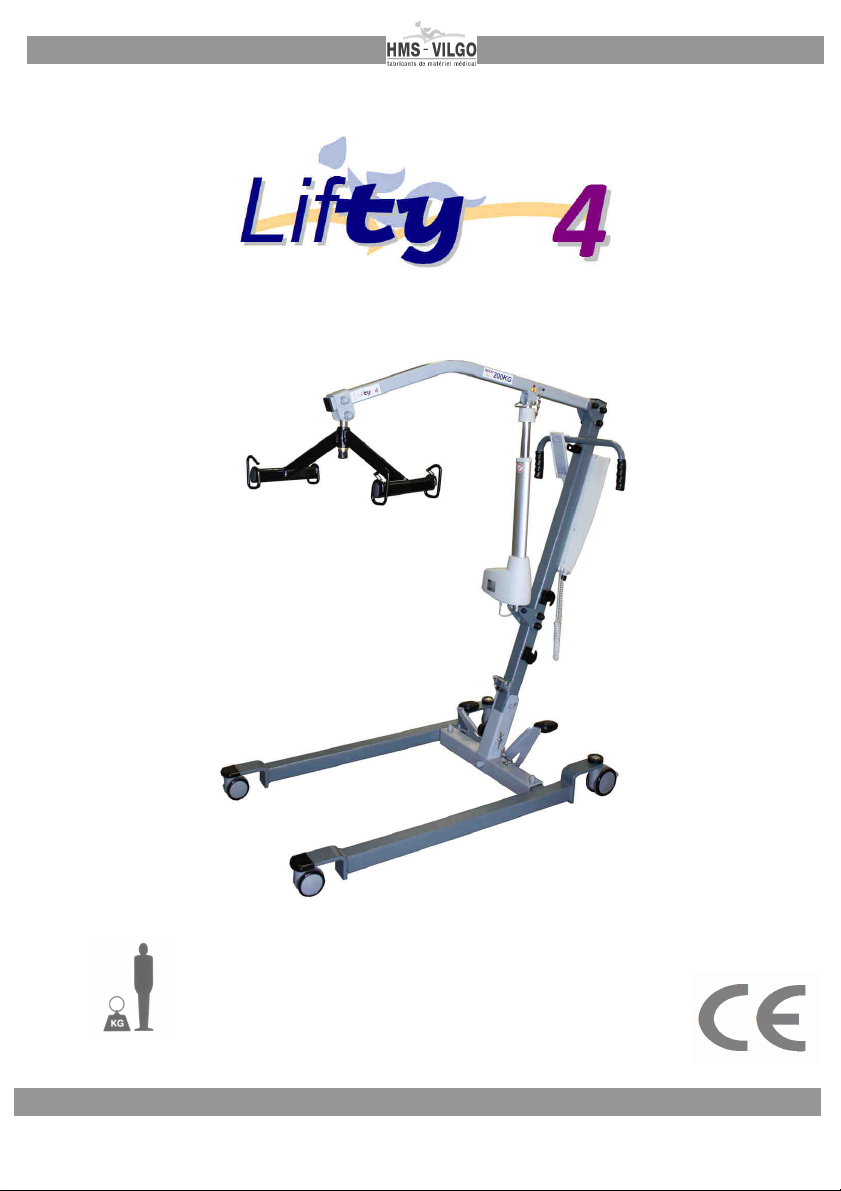
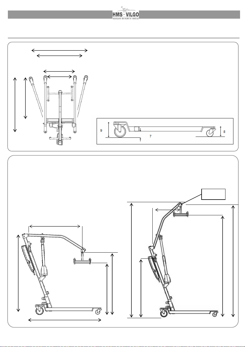
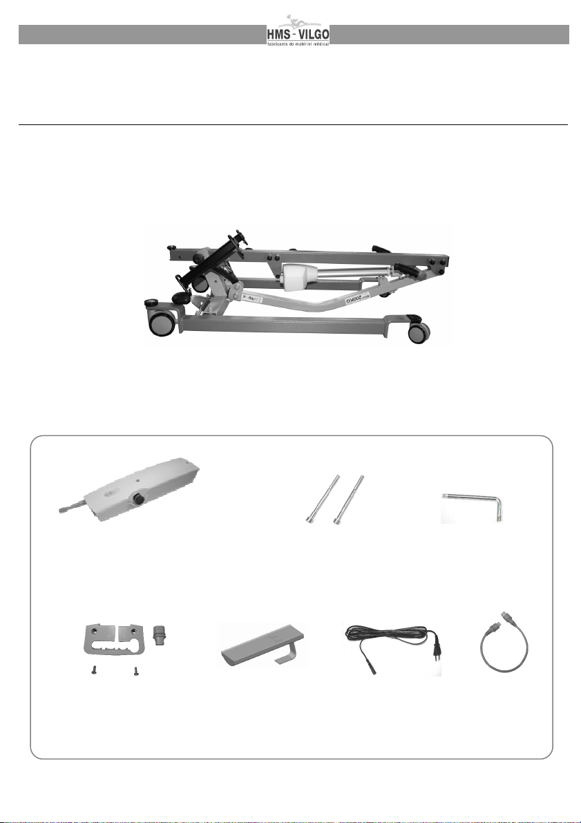
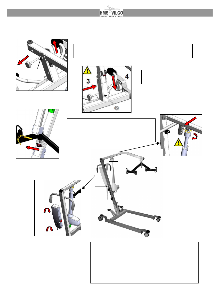
1
LIFTY 4 user guide Version 08/2013
200 Kg / 31.5 stones

2
LIFTY 4 user guide Version 08/2013

3
LIFTY 4 user guide Version 08/2013
August 2013 edition:
All rights reserved. Reproduction of these instructions in whole or in part in any form without express written
permission from HMS-VILGO is strictly prohibited except for private use.
Information is regularly updated in the latest instructions versions. This can not engage the responsibility of
HMS-VILGO in any way.
Warning :
The pics on this leaflet are not under contract.
Therefore, HMS-VILGO has the right to change the products inside anytime.
TABLE OF CONTENTS
1. PREAMBLE ……………………………………………………………………… page 4
2. DESCRIPTION ……………………………………………………………………… page 4-7
2.1. Where to use Lifty4
2.2. General description
2.3. Technical description
2.4. Dimensional characteristics
2.5. Labelling
3. LIFTY4 ASSEMBLING ………………………………………………………
page 7-14
3.1. Package contents
3.2. Lifty4 assembling (page 13)
3.3. Plugging
4. USE …………………………………………………………………………
page 14-17
4.1. First use
4.2. Lifty4 use
4.3. Safety
4.4. Control box operating, battery charge
4.5. Storage instructions
5. LIFTY4 MAINTENANCE ……………………………………………..
page 17-18
5.1. Weekly maintenance
5.2. Annual maintenance
5.3. Lifecycle
5.4. Warranty
5.5. Recycling
Removable central leaflet.
RECOMMENDED CHECKS ………………………………………………………
page 9
EVALUATION OF THE NUMBER OF HOIST OPERATING CYCLES
……
page 10
MAINTENANCE BOOK ………………………………………………………..…
page 11
SPARE PARTS LIST …………...…………………………………
page 12

4
LIFTY 4 user guide Version 08/2013
1. PREAMBLE
Only entitled staff who has read and understood these complete instructions can use Lifty4.
Always use Lifty4 with a person who can belay the patient in case of blackout of the patient or failure of the
hoist.
Use Lifty4 following the maintenance instructions (see Lifty4 maintenance paragraph). If you have any doubt
about Lifty4 operating, please call HMS-VILGO After Sales Service for a diagnostic before using the hoist on a
patient.
HMS-VILGO will not be responsible for damage if these warnings are not followed.
This manual contains all the technical information you need to make a good use of this product. This
information has been carefully checked by HMS-VILGO. This is not an exhaustive list and HMS-VILGO is not
responsible for any kind of mistakes or omissions.
2. DESCRIPTION
2.1. WHERE TO USE LIFTY 4
The Lifty4 is a lifting device. It is used to transfer disabled or elderly people in:
- home medical care for the transfer of a person toward an armchair, a WC seating or chair,
- medical care small structure,
- communities (old people’s home, convalescent home).
Do not use Lifty4 outdoors or on a surface whose declivity could make the patient fell down (>5°).
Before any use of the product :
1- Read the leaflet : It will inform you how to use the product securely and must
be at the disposal of the caring personnel.
2- Product cleaning and disinfection : Please see chapter 5.
3- Connection of the Lifty4 to the electrical network : Please see chapter 4.5
4- Make sure of the good working of all functions.

5
LIFTY 4 user guide Version 08/2013
2.2. GENERAL DESCRIPTION
2.3. TECHNICAL CARACTERISTICS
Materials : steel
Finish : Epoxy paint coating
Class: I
Weight (without support device): 43 kg / 95 lbs
Maximum patient weight to be transferred: 200 kg / 31.5 stones
Electrical equipment conformed to NF EN 60 601-1 and to NF EN 60 601-1-2
Duty cycle: 2 min./18 min. (10%)
Input: 230V ~ 50 HZ
Actuator input : 24 V CC
Battery charge required time : 15 h
Battery autonomy:
±
40 cycles
Electrical equipment protection : Remote control : IP X6
Control box : IPX4
Actuator : IP X4
Pedals
Pole
Control box
Driving handles Support beam
Beam
Side foot
Electric actuator
∅
3 in twin casters
∅
4 in wheels with brake

6
LIFTY 4 user guide Version 08/2013
2.4. DIMENSIONAL CHARACTERISTICS
Dim
ensional characteristics of the base
1 -
Maximum external length :
43.7 in
2 -
Maximum internal length :
33.6 in
3 -
Minimal internal width :
20.5 in
4 -
Minimal external width :
25.6 in
5 -
Maximum internal width :
35.4 in
6 -
Maximum external width :
41 in
7 -
Minimum ground clearance :
1.2 in
8 -
Maximum front height :
3.9 in
9 -
Maximum back height :
5.9 in
Total lift / lifting radius / overall dimension :
1 - Lifting radius at the highest CSP : 29.9 in
2 - Total lift (3-4): 45.8 in
3 - Maximum CSP height : 76 in
4 - Minimal CSP height : 35 in
5 - CSP height at maximum lifting radius : 52 in
6 - Lifting radius at lowest CSP : 35 in
7 - Maximum lifting radius : 37.8 in
8 - Low position floor/hooks height : 26 in
9 - High position floor/hooks height : 67.3 in
10 - Low position overall dimension height : 54 in
11 - High position overall dimension height : 83 in
12 - Overall dimension length : 53.5 in
13 – Floor/handles height : 43.3 in
* CSP : Central Suspension Point
6
5
4
21
3
8
4
6
10
12
11
9
3
CSP
*
1
13

7
LIFTY 4 user guide Version 08/2013
2.5. LABELLING
This label allows you :
To have all the necessary information to make any intervention request for the after sales service thanks to
the serial number and to the reference.
To ensure the follow up of the medical disposal.
It also gives to you the security loading charge for a good use.
There are 3 labels : One on the basis of the Lifty4, one on the electric actuator, and one on the control box.
Standards :
By this label, HMS-VILGO ensures that Lifty4 hoist is conformed to European directive
89/336 referring to electromagnetic compatibility and to European directive 93/42 referring
to medical devices.

8
LIFTY 4 user guide Version 08/2013
3. LIFTY4 ASSEMBLING
3.1. PACKAGE CONTENTS
The following parts are in the package:
1 folded-up Lifty4 hoist :
1 box containing:
Control box (x1)
Main cable
(x1)
Actuator cable
(x1)
Fixing screw
CHC 6x80 (x2)
Anti-pulling up
Cable kit (x1)
Spanner 6 section 5
(x1)

9
LIFTY 4 user guide Version 08/2013
R
RE
EC
CO
OM
MM
ME
EN
ND
DE
ED
D
C
CH
HE
EC
CK
KS
S
Item to check Check
Periodicity : at least once a year and before renting it. * Replacement
after 10 000 cycles
1 Pole / beam support
connection - Check brass ring worn state
- Check fixing screw worn state
- Check stop-nut presence and assembling
2 Control box
- Check emergency stop operating
- Check battery charging
3 Electrical cables - Check cables (pinching, plug state, cut …)
4 Actuator - Check charging operating
5 Actuator / pole
connection - Check fixing screw worn state
- Check stop-nut presence and assembling
6 Pedals - Check pedals operating
- Check connecting rods worn state
7 Back wheels - Check braking system
8 Side foot / cross piece
connection - Check fixing worn state (screw nut + brass rings)
9 Actuator / beam
support connection - Check cotter clip presence and assembling
10 Emergency release
- Check electrical and manual release operating
11 Beam support / beam
axle connection - Check stop-nut presence and assembling
- Check fixing screw worn state
- Check fixing metal tongue welding
12 Beam hooks - Check fixing points of the 4 hooks
- Check welding points worn state
12 Sling - Check seams
13 Beam hooks - check welding and assembling
14 Pole / cross piece
connection - Check removable axle worn state
- Check spigot and safety ring presence
- Check screw / stop-nut connection (presence, worn state and assembling)
- Check pole welding
*See table on page 10 to list necessary spare parts
Hoists are conformed to EN 10 535 standard which means that they can run 11 000 complete cycles under
the conditions of uses they are designed for. Please, carefully consider how important it is to evenly check
and maintain it in order to make sure that it is used under the standard specifications and under ours
recommendations. We will not be responsible for any damage due to an abnormal use or to a too high
number of cycles. You will find all the information you need for your checking and maintenance steps on
pages 9, 10, 11 and 12.
Réf. Document : IB 7.5.1. 704 indice A
5
8
6
3
7
4
2
1
11
14
10
9
12
13

10
LIFTY 4 user guide Version 08/2013
E
EV
VA
AL
LU
UA
AT
TI
IO
ON
N
O
OF
F
T
TH
HE
E
N
NU
UM
MB
BE
ER
R
O
OF
F
H
HO
OI
IS
ST
T
O
OP
PE
ER
RA
AT
TI
IN
NG
G
C
CY
YC
CL
LE
ES
S
This table below, indicates if the replacement of actuator, axis and spare parts is necessary, in function of the
number of runs a day.
number of runs / a day
1
2
3
4
5
6
7
8
9
10
1
365
730
1095
1460
1825
2190
2555
2920
3285
3650
2
730
1460
2190
2920
3650
4380
5110
5840
6570
7300
3
1095
2190
3285
4380
5475
6570
7665
8760
9855
10950
4
1460
2920
4380
5840
7300
8760
10220
11680
13140
14600
5
1825
3650
5475
7300
9125
10950
12775
14600
16425
18250
6
2190
4380
6570
8760
10950
13140
15330
17520
19710
21900
7
2555
5110
7665
10220
12775
15330
17885
20440
22995
25550
8
2920
5840
8760
11680
14600
17520
20440
23360
26280
29200
9
3285
6570
9855
13140
16425
19710
22995
26280
29565
32850
10
3650
7300
10950
14600
18250
21900
25550
29200
32850
36500
11
4015
8030
12045
16060
20075
24090
28105
32120
36135
40150
12
4380
8760
13140
17520
21900
26280
30660
35040
39420
43800
13
4745
9490
14235
18980
23725
28470
33215
37960
42705
47450
14
5110
10220
15330
20440
25550
30660
35770
40880
45990
51100
15
5475
10950
16425
21900
27375
32850
38325
43800
49275
54750
16
5840
11680
17520
23360
29200
35040
40880
46720
52560
58400
17
6205
12410
18615
24820
31025
37230
43435
49640
55845
62050
18
6570
13140
19710
26280
32850
39420
45990
52560
59130
65700
19
6935
13870
20805
27740
34675
41610
48545
55480
62415
69350
20
7300
14600
21900
29200
36500
43800
51100
58400
65700
73000
21 7665
15330
22995
30660
38325
45990
53655
61320
68985
76650
22
8030
16060
24090
32120
40150
48180
56210
64240
72270
80300
23
8395
16790
25185
33580
41975
50370
58765
67160
75555
83950
24
8760
17520
26280
35040
43800
52560
61320
70080
78840
87600
25
9125
18250
27375
36500
45625
54750
63875
73000
82125
91250
26
9490
18980
28470
37960
47450
56940
66430
75920
85410
94900
27
9855
19710
29565
39420
49275
59130
68985
78840
88695
98550
28
10220
20440
30660
40880
51100
61320
71540
81760
91980
102200
29
10585
21170
31755
42340
52925
63510
74095
84680
95265
105850
30
10950
21900
32850
43800
54750
65700
76650
87600
98550
109500
Oldness of the hoist (years)
Foresee actuator, axis and
spare parts replacement.
*
Replace actuator,
axis and spare parts.
Keep using the hoist.
*See spare parts list page 12

11
LIFTY 4 user guide Version 08/2013
M
MA
AI
IN
NT
TE
EN
NA
AN
NC
CE
E
B
BO
OO
OK
K
HOIST REFERENCE:
Serial number :
Date of 1st use:
DATE
/
Number of cycles
evaluated
MAINTENANCE AND QUALITY CHECKING
NAME &
APPROVALS

12
LIFTY 4 user guide Version 08/2013
S
SP
PA
AR
RE
E
P
PA
AR
RT
TS
S
L
LI
IS
ST
T
Part Description Item code Qty Location Replacement
After 11 000
cycles
LA44 -8000N actuator A501216
1 /
CBJH1 control box A501215 1 /
HB71 remote control A501217 1 /
Ø12x91 axle+ black female handle
50M10 + cotter A001274 +
A000527 1
Ø 10 Lg 64+20 articulation pole/cross
piece axle
Ø 8 stop-nut
Ø 8 washer
A501066
A001004
A001062
1
2
2
pole / cross
piece
connection
clip cotter
A501114
1
actuator /
support beam
connection
HH 12x70 screw
Ø 12 stop-nut
Ø 12 washer
D28 Lg135 Lifty 4 beam axle
Ø 28/22 LG 5 brass ring
wrapping beam clevis
HH 12x70 screw
Ø 12 stop nut
A501250
A001080
A001088
A501420
A501421
A501245
A501250
A001080
1
1
2
1
1
1
1
1
support beam /
beam
connection
Ø 10 Lg 64+20 articulation pole/cross
piece axle
Ø 8 stop-nut
Ø 8 washer
pole / actuator Lifty 4 fixing plate
Ø 12 stop nut
HH 12x80 screw
A001128
A001072
A001061
A501244
A001080
A501251
1
2
2
2
2
2
actuator / pole
connection
Ø 40-14.2-e2 brass ring
Lifty4 Ø14-M12-Lg91axle
Ø 12 stop-nut
Ø 12 washer
pole / support beam fixing plate
HH 12x80 screw
Ø 12 stop-nut
A501404
A501402
A001080
A001088
A501400
A001080
A501251
2
1
2
2
2
2
2
pole / support
beam
connection
Ø 40/3.4 brass ring
or
Ø 40/3 brass ring
A001066
A001089
4 Side foot /
cross piece
connection
pedals bushing A000840 4 pedals

13
LIFTY 4 user guide Version 08/2013
3.2. LIFTY4 ASSEMBLING
1/ Unlock
2/
T
ake the axis out of the position
and
p
ick up the pole
.
7
7-8 / Fix the control box to the pole in screwing the 2
cross screws.
9 / Plug the remote control and the electric actuator to
the control box (see chap. 3.3).
Your Lifty4 hoist is now ready to run.
2
1
6
8
5/ Unlock the beam from the support beam
and pick the support beam up.
6/ Fix the head of the electric actuator on
the support beam in locking the clip.
5
3-4 / Put the axle on
position
in locking it
.

14
LIFTY 4 user guide Version 08/2013
3.3. PLUGGING
3.3.1 Plugging/blocking the actuator cable
3.3.2 Unlocking of the actuator cable plug
Unlock with a screw-driver (as shown here), leaning in the notch. In the
same time, turn the ring from the left to the right to unlock the plug.
.
3.3.3 Anti-Pulling up cable kit.
4. USE
4.1. FIRST USE
Even if battery box is immediately ready to run as it is charged when delivered, make sure the hoist
installation has been strictly done as shown on paragraph 3. Test it off load first to get used to it.
3/ Screw the hood to the
control box with a crossed
screw-driver.
3/ Grip the notches and turn
the ring from left to the right.
The cable is locked when the
ring is turned to 90°.
1/ The 3 notches of this
ring show that the griping
device of the cable plug is
unlocked.
2/ Put the cable plug in
position and lean on it
to plunge into the
lodging.
1/ Plug the remote control
and the actuator cables
and plug the shutter.
2/ Put the anti-pulling
up hood in placing the
cables through the
opening.

15
LIFTY 4 user guide Version 08/2013
4.2. LIFTY 4 USE
4.2.1 Sling 20015 installation and operating :
Reminder : Sling is adjustable. User is responsible for adjusting it in order to not hurt the patient. Lifty4 hoist
is delivered with a 20015 sling. See the user instruction bellow.
1/ Put the back of the sling (largest part of the sling) on the patient back in order to have the 2 hanging-up
straps on both sides of the patient.
2/ Hang up each hanging-up strap to the beam hooks (A1 and B2)
3/ Softly lift up the patient right thigh to put the right thigh support underneath.
4/ Softly lift up the patient left thigh to put the left thigh support underneath.
5/ Cross the two thigh support sling.
6/ Hang up each strap to the beam hooks (C3 and D4)
You can adjust the patient tilt with the different hanging-up holes. Make sure to always hang-up the
A and B straps at the same hole level (same colour). Act the same way for C and D straps.
Cautions :
- This sling is designed for HMS-VILGO hoists only.
- Always hang-up the 4 straps at the same level.
- Never adjust straps while the hoist is running.
- Always make sure that straps are well-attached on the beam before lifting the patient up.
- Never exceed the maximum running load.
4.2.2 Transferring the patient:
1/ Set the hoist in a way that the beam stands above the patient (if necessary,
open or close side foot to get closer to the patient).
2/ Lock brakes
3/ Set the sling
4/ Push up button
of the remote control to lift the support beam (make sure
the strap does not get stuck and does not hurt the patient while lifting him).
5/ Unlock brakes to transfer the patient.
6/ Lock brakes again when transfer done.
7/ Push down button
of the remote control to go down
1
2
3
4
A B
C
D
Back of the sling
thigh support straps

16
LIFTY 4 user guide Version 08/2013
4.3. SAFETY
crushing safety: Lifty4 runs with a single-acting actuator. Any obstacle on its way will automatically stop its
going-down.
Emergency stop : the Lifty4 emergency stop button is located on the control box.
Push it to stop the lifting or going-down. Push it again to unlock it.
Electric safety : lifting and going-down are locked when Lifty4 is connected to charge battery.
Alarm : a red led lights on when the actuator is running while battery is low.
Emergency going-down (only use when patient is stuck above and that it is impossible to go down using the
remote control) : There are two actuator release systems:
1/ Electrical release :
To go down, push the blue switch located under the emergency stop.
2/ Manual release :
Push down (1) and turn to the right (2) the red ring of the actuator.
This function can be used if the electrical system is not efficient.
4.4. CONTROL BOX OPERATING, BATTERY CHARGE :
If the charging level is too weak, an alarm sounds (in a constant way) when the control box is activated. The
charging of the battery is then necessary.
The control box has its own integrated charger. To charge batteries, connect the control box to the 220 VAC
main power line, until the green led turn on indicating batteries are charged (approximately 12 hours).
A third person must assist the patient during the
entire emergency going-down process.
The
Lifty 4
must be connected to a network which is in accordance with
the NFC 15
-
100
and NFC 15-211 ( 230 V Electric plug + ground connection) for France and CEI 364 for
other destinations.
Make sure that the power supply of the control box (you can find it on the label), is in
accordance with the establishment power supply.
It is advisable to connect the device on a power fitting protected by a differential circuit
breaker of 30 mA Maximum, in accordance with the CEI 364-5-53 publication.

17
LIFTY 4 user guide Version 08/2013
Warning, the loading of the batteries works only if the emergency button is out of power (put it on the position
‘on’ to load the batteries).
To make batteries last longer, they must be recharged every night.
Reminder: Warranty does not cover batteries.
4.5. STORAGE INSTRUCTIONS:
Do not expose to moisture.
Store in a temperate dry place (5°C to 40°C).
Charge battery before using it after a long time off.
Handling and stocking of the lift has to be done in order to avoid any impact, falling or damage of the material.
5. LIFTY4 MAINTENANCE
5.1 Weekly maintenance
Sling :
Check the sling by looking at its seams condition : immediately replace a sling that starts to show any tear.
Electrical parts:
Test the emergency stop switch while lifting and lowering the support beam.
Look at the electrical cables cover.
Test crushing safety system by placing an item on the support beam going-down way.
Chassis :
Check the brake of the back wheels.
Look at the global geometry on the Lifty4 (no bent item).
Make sure that the 4 wheels are well positioned on the ground.
Make sure that there is no play between the support beam and the pole.
Strap cleaning instructions:
u
86°F (or 30°C) machine wash -
J
Do not dry clean -
d
Do not iron
Emergency stop
LED green color when the
control box is activated
Yellow charging LED
Emergency going down
Actuator connection
Remote control connection

18
LIFTY 4 user guide Version 08/2013
Cleaning of the Lifty4:
Before any intervention on the lifty4, disconnect it from the power and take out the control box.
Follow this cleaning protocol:
5.2 ANNUAL MAINTENANCE
It is recommended to do a complete checking once a year.
You will find on pages 9-12 the checking list and the maintenance book to write down the different
maintenance steps.
5.3 LIFE EXPECTANCY
The life expectancy of the Lifty4 in normal use and maintenance is 5 years.
5.4 WARRANTY
Lifty 4 hoist has a serial number. You will find it on the chassis and on each electronic item.
To make a claim under warranty, you need to return the defective item with its serial number label to your
retailer who will contact us.
The warranty of this product is valid for 5 years. Warranty does not cover battery.
ANY RETURN WITHOUT SERIAL NUMBER LABEL WILL NOT BE COVERED BY THE WARRANTY.
Warranty does not cover breakdown due to a wrong use or maintenance (shock on the battery charger, cut
cable …).
Any breakdown of dysfunction which could be imputable to a modification or replacement by any other spare
part than original ones will affect the warranty.
5.5 RECYCLING
Recycling must be done according to the type of materials and components and in compliance with the
current recycling regulations. Disposal and destruction of the faulty parts must be handled by an agreed
recycling company.
1
-
Impregnate a clean non
-
weaved tissue with
an appropriate cleaning solution (Anios
cleaning and disinfecting high surface solution
or other same solution).
Make sure to respect the right dosage
indicated on the product notice.
2- Clean the all product with the impregnated
non-weaved tissue.
3- Let dry the product.
WARNING:
- Avoid abrupt cleaning and rinsing.
- No high pressure water cleaning.
IMPERATIVELY AVOID:
- Pure alcohol
- Acetone
- Perchlorethylene and trichloroethylene.
- Any solvent or detergent.
- Abrasive cleaning products.
- Any kind of wax.

19
LIFTY 4 user guide Version 08/2013

20
LIFTY 4 user guide Version 08/2013
www.hms-vilgo.com
Distributor stamp
Site de Lille : Parc Eurasanté – 243 Rue Allendé
59120 LOOS LEZ LILLE
Tél : +33 (0)3 20 84 81 50 – Fax : + 33 (0)3 20 59 58 08
Site de Bergerac : Rte de Sainte Alvère - Creysse BP 212
24102 BERGERAC Cedex
Tel. : +33 (0)5 53 74 45 50 – Fax : +33 (0)5 53 63 06 07
Table of contents
Other HMS-VILGO Lifting System manuals
Popular Lifting System manuals by other brands

Power Fist
Power Fist 8880239 manual

Alico
Alico Snap-on Equipment EELR571A Installation and operation manual

FAL
FAL VL35F230B Installation and operating instructions

Equalizer
Equalizer VLW18TE Operator's instruction manual

Payne
Payne Pallet Retriever Operator's manual

Nussbaum
Nussbaum 4.80 H SST Operating Manual and Inspection Book