Strongarm 218 User manual
PROD NO. 030321
MOD NO. 218
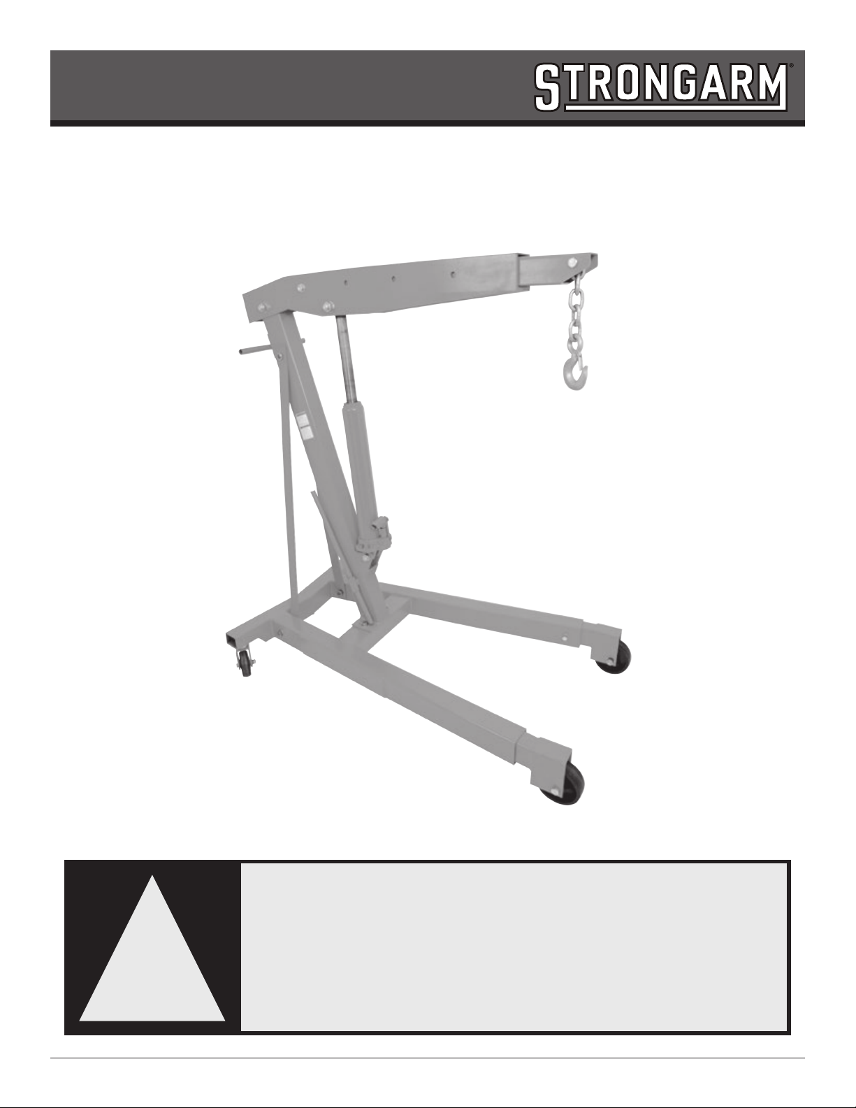
3 Ton Engine Crane – Heavy Duty
Operating Instructions
www.strongarminc.com
WARNING:
Read all instructions and safety warnings before
operating this equipment. Failure to follow the
instructions and safety warnings may result in
personal injury or property damage.
!

www.strongarminc.com
WARNING
• Study understand, and follow all instructions before operating this device.
• When using various shop equipment, basic safety precautions should always be followed.
• Keep work area clean and free from debris.
• Keep children away from work area and shop equipment. Keep hands and feet from loading area.
• Do not exceed rated capacity, keeping in mind the position of the boom determines the capacity.
• Use only on a hard level surface.
• Prior to lifting, ensure the legs are extended and xed according to the boom position in such a way as to
provide the maximum stability of the jack and load being lifted.
• Do not go underneath a load that is being lifted or suspended.
• Before moving, lower the load to the lowest possible point, extra caution should be taken to ensure that the
load does not swing beyond the wheels or legs causing the load and crane to tip over.
• Use only slings or chains with a rated capacity greater than the weight of the load being lifted.
• Do not allow the load to swing or drop violently while lowering or moving.
• Ensure the user is familiar with the controls and operational characteristics of this product and aware of the
potential hazards associated with its use.
• No alterations shall be made to this product.
• Failure to heed these instructions may result in personal injury and/or property damage.
WARNING
The use of shop equipment is subject to certain hazards that cannot be prevented by mechanical means, but
only by exercise of intelligence, care, and common sense. It is therefore essential to have personnel involved in
the use and operation of equipment who are careful, competent, trained, and qualied in the safe operation of
this equipment and its proper use. Examples of hazards are dropping, tipping, or slipping of parts/components
caused primarily by improperly securing loads, overloading, off-centered loads, use on other than hard level
surfaces, and using equipment for a purpose for which it was not designed.
The owner and / or operator shall study and understand the product and safety instructions before operating
this equipment. Safety information shall be emphasized and understood. If the operator is not uent in English,
the product and safety instructions shall be read to and discussed with the operator in the operator’s native
language by the purchaser / owner or his designee, making sure that the operator comprehends their contents.
A copy of these instructions / warnings shall be retained for future reference.
INSPECTION
Visual inspection shall be made before each use of this equipment, checking for abnormal conditions, such as
cracked welds, leaks, damaged, loose or missing parts. This equipment shall be removed immediately from
service if it is believed to have been subjected to an abnormal or shock load, the equipment shall be inspected
by a qualied repair facility. Owners and / or operators should be aware that repair of this equipment may
require specialized knowledge and facilities. It is recommended that this equipment be inspected annually
by a qualied repair facility. Defective parts, decals, safety labels or signs should be replaced with Strongarm
specied parts.

www.strongarminc.com
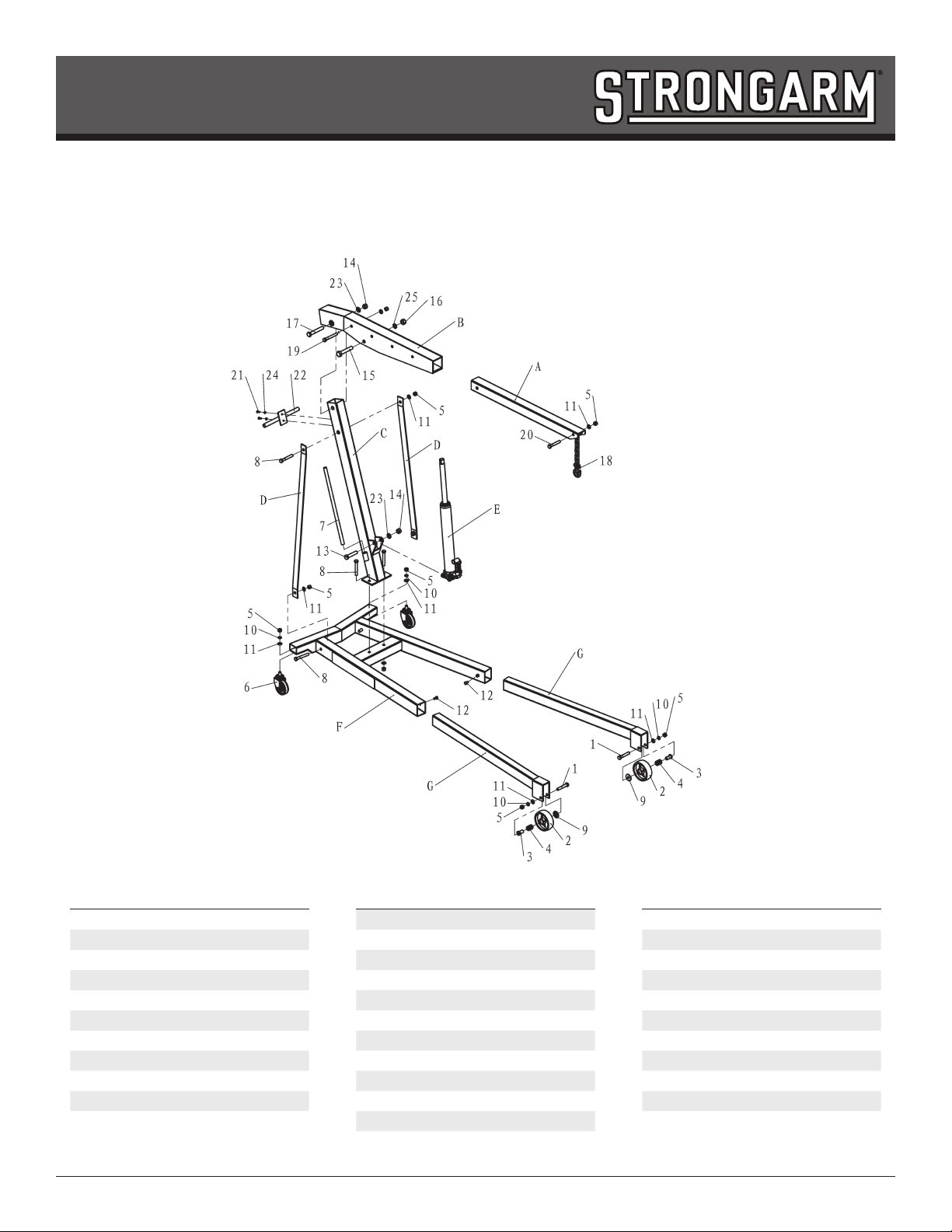
ASSEMBLY
Use the parts drawing as your guide to assembly. Lay all parts and assemblies out in front of you before
beginning. We recommend 2 people and the following procedure:
1) Attach rear Caster Wheels (#6) to rear of Base (F)
2) Insert Leg (G) into Base (F) and lock into position using bolt (#12)
From this point, it is recommended that you leave a “loose t until you have all of the components assembled
and then tighten each piece once nished.
3) Attach Support Post (C) to Base (F).
4) Attach Support Brackets (D) to Support Post (C) and Base (F)
5) Attach Boom (B) to Support Post (C)
6) Attach bottom of Hydraulic Ram (E) to Support Post (C)
7) Attach top of Hydraulic Ram (E) to Boom (B)
At this time go around all of the components and ensure that all nuts and bolts are tight.
8) Insert Boom Extension (A) into Boom (B) and secure.
9) Attach Positioning Handle (#22) to Support Post (C)
10) Attach Swivel Hook (#18) to Boom Extension (A)
OPERATING
Lifting
1) Adjust the boom position to the appropriate position for the load being lifted and secure with the nut and
bolt provided.
2) Ensure the legs are extended and xed according to the boom position in such a way as to provide the
maximum stability of the jack and load being lifted.
3) Using the end of the jack handle, turn the release valve clockwise until tight (do not overtighten).
4) Insert the jack handle into the pump receiver and operate the pump until the desired height is attained.
Lowering
1) Using the end of the jack handle, SLOWLY turn the release valve counterclockwise until the load begins
to lower.
2) There is never any reason to turn the release valve more than 2 full turns counterclockwise

www.strongarminc.com
MAINTENANCE
1) Use a good grade of hydraulic jack oil. Never mix different types of uid.
2) Store the crane in the retracted position to protect the ram from dirt and water which will eventually cause
rust and could damage the internal seals.
3) Moving parts should be lubricated once a month using a general purpose grease.
4) Hydraulic repairs should be performed by a qualied hydraulic technician.
AIR PURGE
Sometimes air will get trapped in the hydraulic system during transportation or normal operation, to purge air
from the jack, perform the following steps:
1) Open the release valve by turning it counterclockwise two full turns.
2) Pump the handle 12 full strokes.
3) Close the release valve by turning it clockwise until tight (do not overtighten).
4) Pump the jack until the ram is extended to its maximum height.
5) If air is still present, repeat steps 1 through 4.
PROD NO. 030321
MOD NO. 218
www.strongarminc.com
3 Ton Engine Crane – Heavy Duty
Parts Breakdown
No. Description Qty.
A Boom Extension 1
B Boom 1
C Upright Mast 1
D Mast Braces 2
E Hydraulic Ram 1
F Base 1
G Leg Extension 2
1 Bolt M16 x 95 2
2 Wheels 2
3 Bushing 2
4 Needles 32
No. Description Qty.
5 Nut M16 11
6 Caster Wheels 2
7 Jack Handle 1
8 Bolt M16 x 110 5
9 Bearing Covers 2
10 Spring Washer 16 4
11 Washer 16 11
12 Set Screw M12 x 20 2
13 Bolt M20 x 100 1
14 Nut M20 2
15 Bolt M22 x 125 1
No. Description Qty.
16 Nut M22 1
17 Bolt M20 x 135 1
18 Hook and Chain 1
19 Bolt M16 x 120 1
20 Bolt M16 x 100 1
21 Bolt M8 x 20 2
22 Handle 1
23 Washer 20 2
24 Washer 8 2
25 Washer 22 1
Table of contents


