Strongarm 814B User manual
1
WARNING:
Read all instructions and safety warnings before
operating this equipment. Failure to follow the
instructions and safety warnings may result in
personal injury or property damage.
!
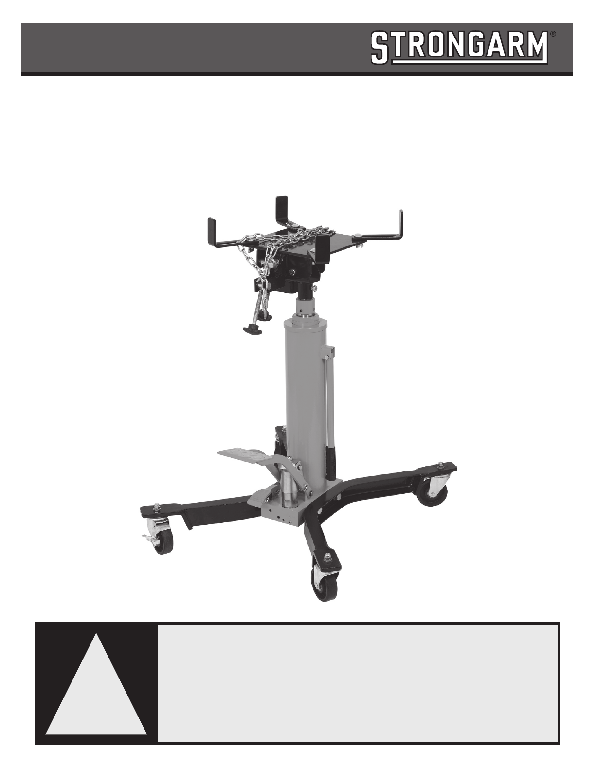
PROD NO. 030535
MOD NO. 814B
1/2 Ton High Lift Transmission Jack
Owner’s Manual

2
!SETUP
Visually inspect all components for shipping damage. If any shipping damage is found, nofy carrier at once. Shipping damage is NOT covered by
warranty. The carrier is responsible for all repair or replacement cost resulng from damage in shipment.
1 Take out all the parts from the wooden box.
2 Connect 4 casters (44) with Base Assembly (40) by using Nut (41), Lock Washer (42) and Flat Washer (43).
3 Connect Adaptor (48) with the piston of the pump.
4 Aach 4 Safety Pieces (S02) to the adaptor (S03) by using Bolt (S01), Washer (S04) and Wing Nut (S05).
5 Connect Chain (S26) with Plate (S03) by using Bolt (S27), Washer (S25) and Nut (S24).
6 Aach Hook (S06) with Base by Using Wing Nut (S08). And then connect the whole assembly with the plate (S03) by using Washer (S22)
and Nut (S23).
!WARNING!
• The technician using this jack must be trained, qualied, fully familiar with safe work pracces, and have prior experience in the use of
hydraulic equipment. Lack of knowledge in any of these areas can lead to equipment damage and/or personal injury.
• Read, understand, and follow all instrucons before operang this jack.
• Inspect the jack before each use. Do not use jack if damaged, altered, modied, leaking hydraulic uid or with missing or loose components.
• Never modify or weld hydraulic equipment.
• Never li more that the rated capacity of the jack: overloading causes equipment failure and possible personal injury.
• The jack is a load liing device, not a load holding device. Once the load is raised, it must always be rmly supported with auxiliary stands.
Never work under or around a load supported only by hydraulic devices.
• Never put unbalanced or o-centre loads on the jack saddle. Use saddle adapters and saddle extenders along with straps and chains to secure
load to the saddle head. Incorrect loading can result in equipment failure.
• This jack was designed for liing transmissions only. Consult the vehicle manufacturer for the transmission's centre of balance.
• Secure the transmission to the jack’s saddle with the anchorage restraint system provided before raising or lowering the transmission.
• Use of this product is limited to the removal, installaon and transportaon in the lowered posion. Jack should only be used on a at, clean,
unobstructed concrete oor.
• Always wear safety glasses and/or other protecve equipment that meet or exceed ANSI Z87.1 and OSHA standards.
• Use the jack ONLY on hard, level surfaces capable of sustaining the load.
!WARNING!
1. SERVICE/INSPECTION
Visual inspecon shall be performed before each use of this equipment and its adapters, checking for abnormal condions, such as cracked
welds, leaks, and damaged, loose or missing parts. This equipment shall be removed immediately from service if it is believed to have been
subjected to an abnormal or shock load and shall be inspected by a qualied repair facility. Owners and/or operators should be aware that repair
of this equipment may require specialized knowledge and facilies. It is recommended that this equipment be inspected annually by a qualied
repair facility. Defecve parts, decals, safety labels or signs should be replaced with Strongarm specied parts.
The use of shop equipment is subject to certain hazards that cannot be prevented by mechanical means, but only by exercise of intelligence, care, and
common sense. It is therefore essenal to have personnel involved in the use and operaon of equipment who are careful, competent, trained, and
qualied in the safe operaon of this equipment and its proper use when servicing motor vehicles and their components. Examples of hazards are
dropping, pping, or slipping of motor vehicles or their components caused primarily by improperly securing loads, overloading, o-centered loads,
use on other than hard level surfaces, and using equipment for a purpose for which it was not designed. Only Strongarm aachments and/or adapters
may be used on this equipment.
The owner and/or operator shall study and understand the product and safety instrucons before operang this equipment. Safety informaon shall
be emphasized and understood. If the operator is not uent in English, the product and safety instrucons shall be read to and discussed with the
operator in the operator’s nave language by the purchaser/owner or his designee, making sure that the operator comprehends their contents. A
copy of these instrucons/warnings shall be retained for future reference.

3
operation
!MAINTENANCE
1. When not in use, store the jack in a dry locaon with saddle in lowest posion.
2. Periodically check the piston rod for signs of rust or corrosion. Clean exposed areas with a clean oiled cloth.
Warning: Never use sandpaper or abrasive material on these surfaces!
3. A coang of light lubricang oil to pivot points, axles and hinges will help to prevent rust and assure that castors, foot pedal and pump
assemblies move freely. Periodically lubricate the pivot points, axles and hinges with a light lubricang oil as needed.
4. With jack in its lowest posion, remove the air vent screw (25) to check the hydraulic oil level. If it is not adequate, add high quality
hydraulic jack oil as necessary. Insert and ghten the air vent screw. Then purge away air from hydraulic system as described in purging.
Warning: DO NOT use brake uid or any other improper uid and avoid mixing dierent types of oil when adding hydraulic oil.
5. To ensure best performance and longer equipment life, replace the complete hydraulic oil at least once a year. With jack in its lowest
posion, remove the air vent screw (25), lay the jack on its side and drain the oil into a suitable container. Ensure that no dirt gets into
the system. Set the jack in its level upright posion, ll with approved hydraulic jack oil. Then replace the air vent screw (25) and purge
away air from hydraulic system as described in purging air.
Note: Dispose of hydraulic oil in accordance with local regulaons.
6. When equipment eciency drops, purge away air from hydraulic system.
7. It is recommended that an annual inspecon be done by qualied technicians.
WARNING!
Ensure that you read, understand and apply the safety instrucons and warnings before use. Failure to heed these instrucons may result in property
damage and/or personal injury.
1. Roll the transmission jack into posion and pump the foot pedal (35) unl saddle reaches desired height.
NOTE: Follow vehicle manufacturer’s recommended procedures for removing the load as outlined in vehicle service manual or repair guide.
2. Carefully center load on the saddle. Ensure the load's center of gravity is centered on the saddle and the setup is stable and secure.
NOTE: Before lowering load check to ensure all tools and personnel are clear and it is safe to lower the load.
3. SLOWLY and CAREFULLY operate the release pedal 32 to lower the load to its lowest possible posion.
4. If necessary, CAREFULLY and SLOWLY move the jack.
5. Transfer load immediately to appropriate support device for service or repair.

4
PURGING AIR FROM THE HYDRAULIC SYSTEM.
!TROUBLE SHOOTING GUIDE
Trouble Cause Soluon
Unit fails to extend or
extends parally
1.Low uid level 1.Refer to maintenance secon and ll to
correct uid level
Incomplete or spongy
cylinder response when
foot pedal is pumped
1.Low uid level 1.Fill to correct uid level
2.Air in system 2.Follow Purge Air in the hydraulic system.
3.Pressure is low 3.Pressure regulang again
Unit fails to extend when
foot pedal is pumped
1. Release the jack. 1.Operate the foot pedal and release
pedal together.
2.Contaminaon 2.Disassemble and clean unit
5
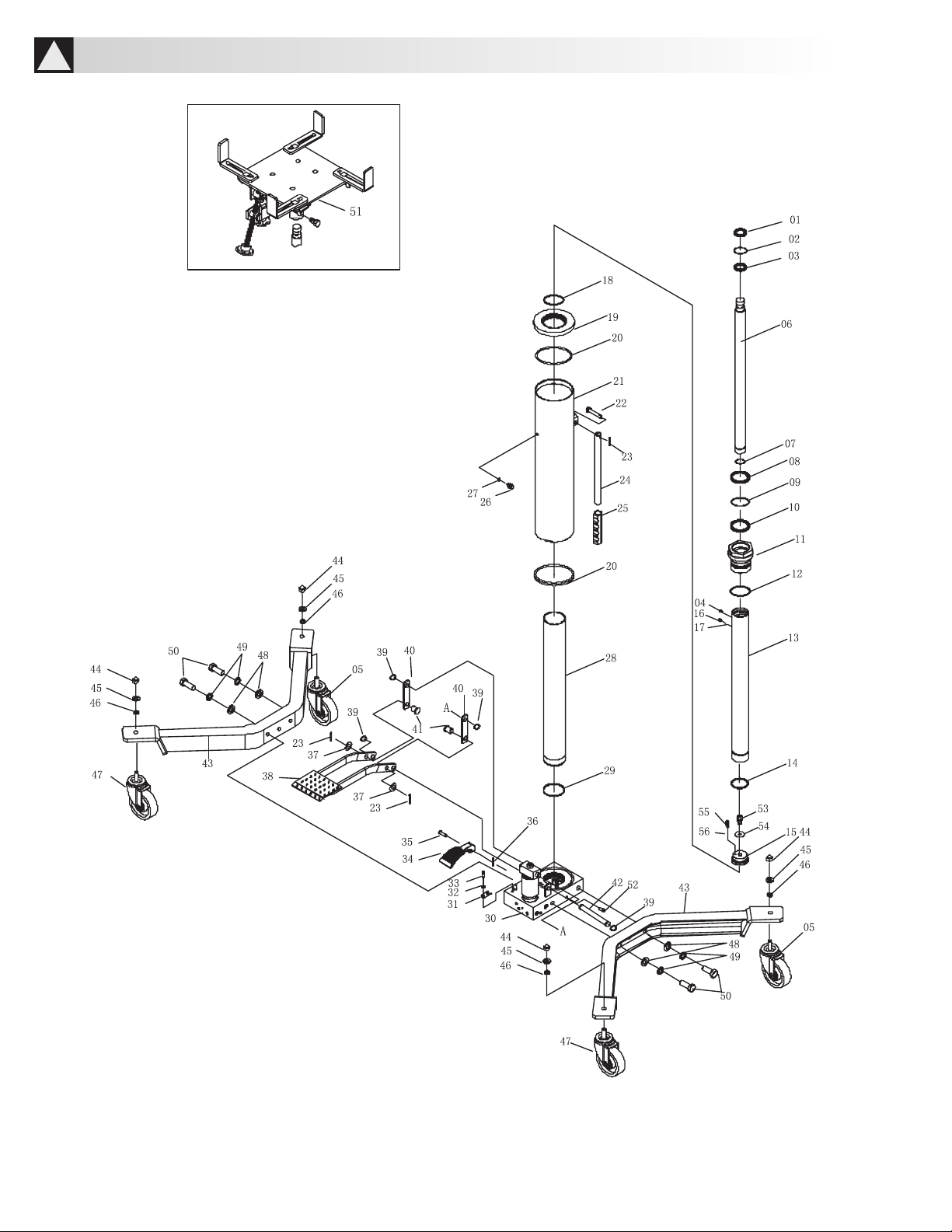
!PARTS

6
Parts No.DescriponQtyParts No.DescriponQty
1Dust ring 1 29 Washer 1
2O-ring 130 Pump 1
3 U-ring 131 U-limited 1
4Oil cup 132 Lock washer 1
5Caster 2 33 Screw 1
6 Second piston rod 134 Release pedal 1
7Retainer ring 1 35 Pin 1
8 Dust ring 136 Coer pin 1
9O-ring 137 Washer 2
10 U-ring 138 Foot pedal 1
11 Round nut 1 39 Retainer ring 4
12 O-ring 140 Connect rod 2
13 First piston rod 1 41 Pin 2
14 Limited ring 1 42 Pin 1
15 Plunger 143 Legs 2
16 Screw 1 44 Nut 4
17 Steel 145 Lock washer 4
18 O-ring 146 Washer 4
19 Round nut base 147 Caster with brake 2
20 Washer 248 Washer 4
21 Oil tank 1 49 Lock washer 4
22 Pin 150 Bolt 4
23 Coer pin 3 51 Saddle 1
24 Handle 152 Screw 2
25 Handle cover 153 Second Limited valve 1
26 Exhaust screw 154 Washer 1
27 Seal ring 155 Spring 1
28 Ram 1 56 Steel ball 1
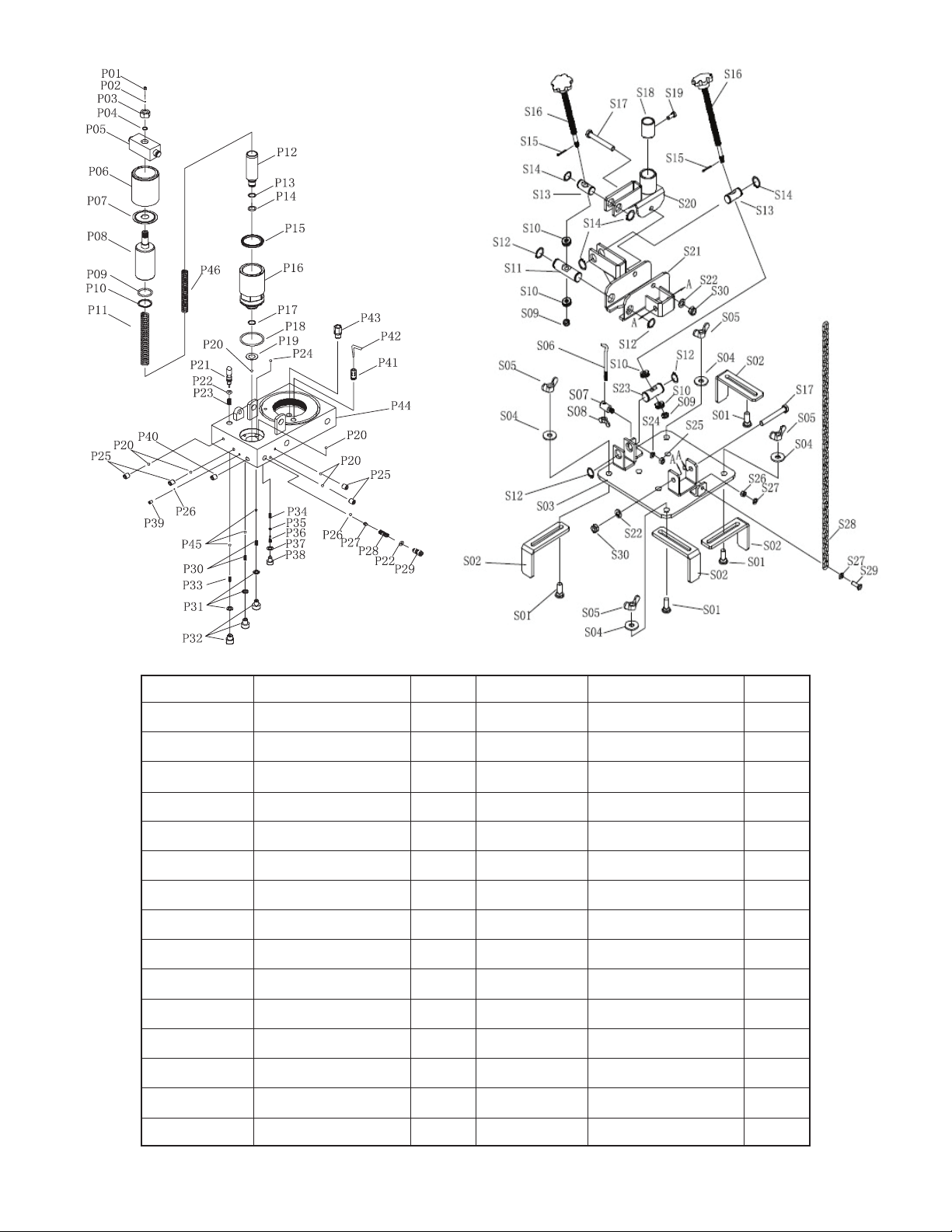
!PARTS LIST
7
Parts No.DescriponQtyParts No.DescriponQty
S01Bolt 4S16AdjustedHandle 2
S02Block4S17Bolt 2
S03 Plate1S18Cover1
S04Washer4S19Bolt 1
S05 Nut 4S20Saddle Base 1
S06 Chain Hook1S21PlateCarrier1
S07 Hook Base 1S22 Washer2
S08Nut 1 S23 Pin21
S09Nut 2S24Washer1
S10Bear4S25 Nut 1
S11 Pin 1 S26Nut 1
S12Retainer Ring 4 S27Washer2
S13 Pin12S28Chain 1
S14Retainer Ring 4 S29 Bolt 1
S15 Coer Pin2S30 Nut 2

8
Parts No.Parts No.QtyParts NoDescriponQty
P2 Steel Ball 1P25 Screw 4
P3 Nut 1P26 Steel Ball 2
P4 O-Ring 1P27 Steel Ball Base 1
P5 Pin Cover 1P28 Spring 1
P6 Dust Cover 1P29 Screw 1
P7 Dust Plunger 1P30 Spring 2
P8 Big Pump Core 1P31 Washer 3
P9 O-Ring 1P32 Screw 3
P10 Washer 1P33 Spring 1
P11 Spring 1P34 Spring 1
P12 Small Pump Core 1P35 O-Ring 1
P13 Washer 1P36 Push Rod 1
P14 O-Ring 1P37 Copper Washer 1
P15 U-Ring 1P38 Screw 1
P16 Pump Core Base 1P39 Screw 1
P17 Retainer Ring 1 P40 Screw 1
P18 O-Ring 1P41 Connector 1
P19 Smal Copper Washer 1P42 Filter 1
P20 Steel Ball 6 P43 First Limited Valve 1
P21 Release Valve Core 1P44 Pump 1
P22 O-Ring 2P45 Steel Ball 3
P23 Spring 1P46 Spring 1
Table of contents
Other Strongarm Jack manuals


Popular Jack manuals by other brands

Omega Lift Equipment
Omega Lift Equipment 18122C Operating instructions & parts manual

Pittsburgh
Pittsburgh 58816 Owner's manual & safety instructions

Unimec
Unimec TP Assembly instructions

Sonic
Sonic 4800703 instructions

BGS technic
BGS technic 70039 instruction manual

TradeQuip
TradeQuip 1128T owner's manual

VEVOR
VEVOR TJD-12000SP-F quick start guide

ULTIMATE SPEED
ULTIMATE SPEED URW 2 A1 HYDRAULIC TROLLEY JACK operating instructions

Stels
Stels 51131 user manual

Bushranger
Bushranger RJX01 instruction manual

Clarke
Clarke CTJ2500QLG Operating & maintenance instructions

Valex
Valex 1650520 Translation of the original instructions


