StrongLink SL030 User manual

RFID MODULE
Mifare Read/Write Module
SL030
User Manual
Version 1.3
Dec 2006
StrongLink

StrongLink SL030
CONTENT
1. MAIN FEATURES.................................................................................. 3
2. PINNING INFORMATION................................................................... 4
3. DEVICE OPERATION.......................................................................... 5
3-1. CLOCK and DATA TRANSITIONS:.................................................................... 5
3-2. START CONDITION .............................................................................................. 5
3-3. STOP CONDITION................................................................................................. 5
3-4. ACKNOWLEDGE ................................................................................................... 5
3-5. BUSY STATE ........................................................................................................... 6
3-6. Device Addressing..................................................................................................... 6
3-7. Write Operations...................................................................................................... 6
3-8. Read Operations....................................................................................................... 7
4. COMMAND DESCRIPTION ............................................................... 7
4-1. Format ...................................................................................................................... 7
4-2. Command Overview................................................................................................ 8
4-3. Command List.......................................................................................................... 9
4-3-1. Select Mifare card ................................................................................................ 9
4-3-2. Login to a sector ................................................................................................... 9
4-3-3. Read a data block................................................................................................. 9
4-3-4. Write a data block.............................................................................................. 10
4-3-5. Read a value block.............................................................................................. 10
4-3-6. Write a value block ............................................................................................ 10
4-3-7. Write master key (KeyA)................................................................................... 11
4-3-8. Increment value.................................................................................................. 11
4-3-9. Decrement value................................................................................................. 11
4-3-10. Copy value........................................................................................................... 12
4-3-11. Read a data page (Mifare_UltraLight)............................................................. 12
4-3-12. Write a data Page (Mifare_UltraLight)........................................................... 12
4-3-13. Power Down........................................................................................................ 12
http://www.stronglink.cn 2

StrongLink SL030
1. MAIN FEATURES
•Tag supported: Mifare 1K, Mifare 4K, Mifare UltraLight
•Auto detecting tag
•Built-in antenna
•0 to 400 kHz bit-wide I2C-bus communication
•DC2.5V to DC3.6V VDD operating, I/O pins are 5V tolerant
•Work current less then 40mA @3.3V
•Power down current less then 10uA
•Operating distance: Up to 50mm, depending on tag
•Storage temperature: -40 ºC ~ +85 ºC
•Operating temperature: -25 ºC ~ +70 ºC
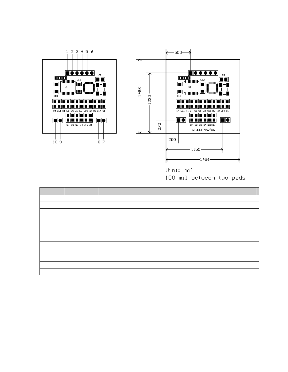
•Dimension: 38 × 38 × 3 mm
•The OUT pin is low level indicating tag in, and high level indicating tag
out
http://www.stronglink.cn 3
StrongLink SL030
2. PINNING INFORMATION
PIN SYMBOL TYPE DESCRIPTION
1 VDD PWR Power supply, DC2.5V to DC3.6V
2 IN Input Falling edge wake up SL030 from power down mode
3 SDA Input/Output Serial Data Line
4 SLC Input Serial Clock Line
5 Out Output Tag detect signal
low level indicating tag in
high level indicating tag out
6 GND PWR Ground
7 NC
8 NC
9 NC
10 NC
http://www.stronglink.cn 4
StrongLink SL030
3. DEVICE OPERATION
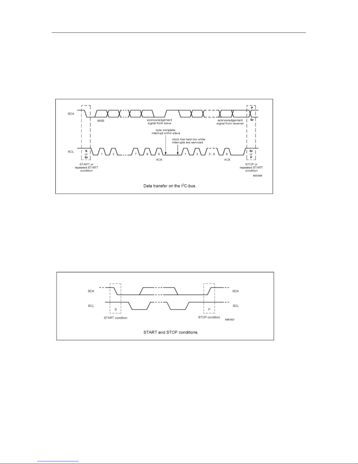
3-1. CLOCK AND DATA TRANSITIONS:
The SDA pin is normally pulled high with an external device. Data on the SDA pin may
change only during SCL low time periods. Data changes during SCL high periods will
indicate a start or stop condition as defined below.
3-2. START CONDITION
A high-to-low transition of SDA with SCL high is a start condition which must precede any
other command
3-3. STOP CONDITION
A low-to-high transition of SDA with SCL high is a stop condition.
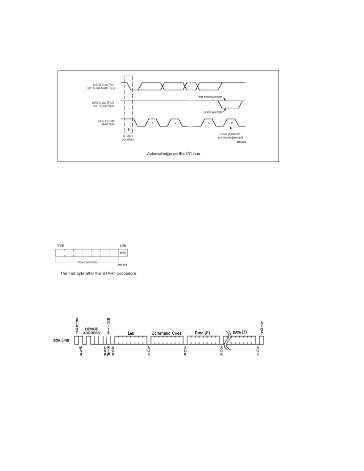
3-4. ACKNOWLEDGE
All addresses and data words are serially transmitted to and from the SL030 in 8-bit words.
The SL030 sends a zero to acknowledge that it is not busy,and has received each word.
This happens during the ninth clock cycle.
http://www.stronglink.cn 5
StrongLink SL030
3-5. BUSY STATE
When the SL030 has received command, then don’t acknowledge IIC bus until ends with
the card communication.
3-6. Device Addressing
The SL030 devices require an 8-bit device address word following a start condition to
enable the chip for a read or write operation.
The device address word consists of 7 bits addressing and 1 bit operation select bit.
The first 7 bits are the SL030 addressing, is 1010000
The eighth bit of the device address is the read/write operation select bit. A read operation
is initiated if this bit is high and a write operation is initiated if this bit is low.
3-7. Write Operations
The host device send a command(refer chapter 4) to SL030 via write operation, then SL030
will carry out the order that receive. Finished time according to different order
http://www.stronglink.cn 6
StrongLink SL030
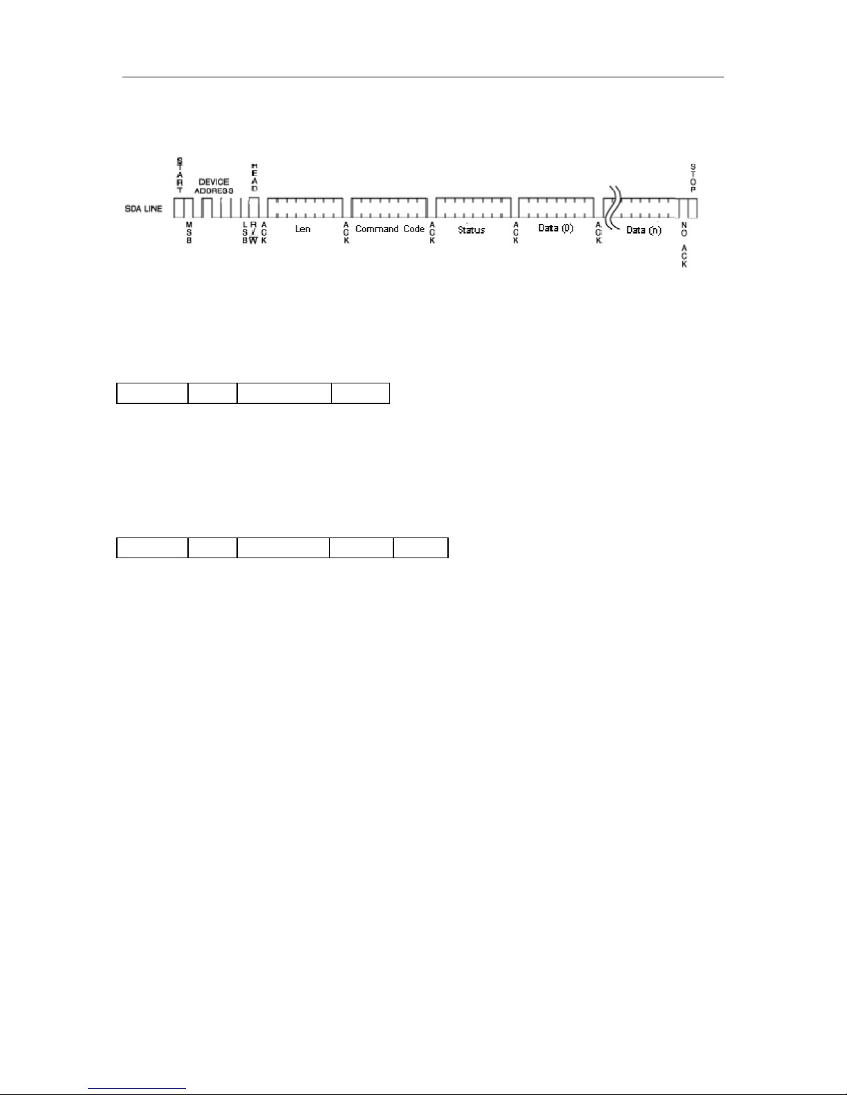
3-8. Read Operations
The host device passes to read the operation gets the order carries out the result
4. COMMAND DESCRIPTION
4-1. FORMAT
Host Write Command to SL030:
Address Len Command Data
Address: 1 byte, 0xA0
Len: Byte length counting from Command Code to the last byte of the data,
1 byte.
Command: Command Code, 1 byte.
Data: Data, variable length depends on the command type.
Host Read The Result:
Address Len Command Status Data
Address: 1 byte, 0xA1
Len: Byte length counting from Command Code to the last byte of the data,
1 byte.
Command: Command Code, 1 byte
Status: Command status, 1 byte
Data: Data, variable length depends on the command type.
http://www.stronglink.cn 7

StrongLink SL030
4-2. COMMAND OVERVIEW
Command Description
0x01 Select Mifare card
0x02 Login to a sector
0x03 Read a data block
0x04 Write a data block
0x05 Read a value block
0x06 Write a value block
0x07 Write master key (key A)
0x08 Increment value
0x09 Decrement value
0x0A Copy value
0x10 Read a data page (ultra_light)
0x11 Write a data page (ultra_light)
0x50 Go to Power Down mode
STATUS OVERVIEW
Status Description
0x00 Operation success
0x01 No tag
0x02 Login success
0x03 Login fail
0x04 Read fail
0x05 Write fail
0x06 Unable to read after write
0x0A Collision occur
0x0C Load key fail
0x0D Not authenticate
0x0E Not a value block
http://www.stronglink.cn 8

StrongLink SL030
4-3. COMMAND LIST
4-3-1. Select Mifare card
Host Write:
Len 0x01
Host Read:
Len 0x01 Status Serial num Type
Status: 0x00: Operation success
0x01: No tag
0x0A: Collision occur
Serial num: Serial number of the card detected if the operation is success, 4 bytes for
Mifare Standard & Mifare ProX, 7 bytes for Mifare UltraLight & Mifare DesFire
Type: 0x01: Mifare Standard 1K card
0x02: Mifare Pro card
0x03: Mifare UltraLight card
0x04: Mifare Standard 4K card
0x05: Mifare ProX card
0x06: Mifare DesFire card
4-3-2. Login to a sector
Host Write:
Len 0x02 Sector Type Key
Sector: Sector need to login
Type: Key type (0xAA: authenticate with KeyA, 0xBB: authenticate with KeyB)
Key: Authenticate key, 6 bytes
Host Read:
Len 0x02 Status
Status: 0x02: Login success
0x01: No tag
0x03: Login fail
0x0C: Load key fail
4-3-3. Read a data block
Host Write:
Len 0x03 Block
Block: The block number to be read, 1 byte
Host Read:
Len 0x03 Status Data
Status: 0x00: Operation success
0x04: Read fail
0x0D: Not authenticate
0x01: No tag
Data: Block data returned if operation is success, 16 bytes.
http://www.stronglink.cn 9

StrongLink SL030
4-3-4. Write a data block
Host Write:
Len 0x04 Block Data
Block: The block number to be written, 1 byte.
Data: The data to write, 16 bytes.
Host Read:
Len 0x04 Status Data
Status: 0x00: Operation success
0x01: No tag
0x05: Write fail
0x06: Unable to read after write
0x07: Read after write error
0x0D: Not authenticate
Data: Block data written if operation is success, 16 bytes.
4-3-5. Read a value block
Host Write:
Len 0x05 Block
Block: The block number to be read, 1 byte.
Host Read:
Len 0x05 Status Value
Status: 0x00: Operation success
0x01: No tag
0x04: Read fail
0x0D: Not authenticate
0x0E: Not a value block
Value: Value returned if the operation is success, 4 bytes.
4-3-6. Write a value block
Host Write:
Len 0x06 Block Value
Block: The block number to be written, 1 byte.
Value: The value to write, 4 bytes.
Host Read:
Len 0x06 Status Value
Status: 0x00: Operation success
0x01: No tag
0x05: Write fail
0x06: Unable to read after write
0x07: Read after write error
0x0D: Not authenticate
Value: Value written if the operation is success, 4 bytes.
http://www.stronglink.cn 10
Other manuals for SL030
1
Table of contents
Other StrongLink Control Unit manuals


Popular Control Unit manuals by other brands

Festo
Festo Compact Performance CP-FB6-E Brief description

Elo TouchSystems
Elo TouchSystems DMS-SA19P-EXTME Quick installation guide

JS Automation
JS Automation MPC3034A user manual

JAUDT
JAUDT SW GII 6406 Series Translation of the original operating instructions

Spektrum
Spektrum Air Module System manual

BOC Edwards
BOC Edwards Q Series instruction manual

KHADAS
KHADAS BT Magic quick start

Etherma
Etherma eNEXHO-IL Assembly and operating instructions

PMFoundations
PMFoundations Attenuverter Assembly guide

GEA
GEA VARIVENT Operating instruction

Walther Systemtechnik
Walther Systemtechnik VMS-05 Assembly instructions

Altronix
Altronix LINQ8PD Installation and programming manual


