StrongLink SL025B User manual

RFID MODULE
Mifare Reader / Writer
SL025B
User Manual
Version 3.0
Jan 2018
StrongLink

StrongLink SL025B
http://www.stronglink-rfid.com
2
CONTENT
1. MAIN FEATURES...............................................................................3
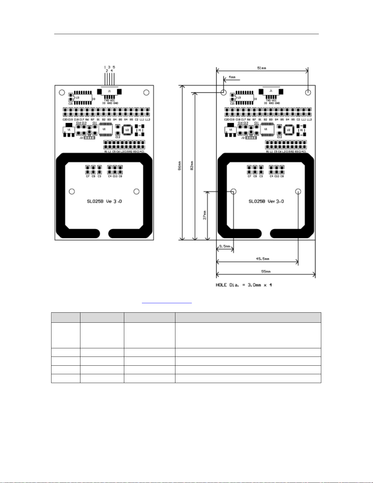
2. PINNING INFORMATION...................................................................4
3. BAUD RATE SETTING.........................................................................5
4. COMMUNICATION PROTOCOL.......................................................5
4-1. COMMUNICATION SETTING .....................................................................5
4-2. COMMUNICATION FORMAT .....................................................................5
4-3. COMMAND OVERVIEW............................................................................6
4-4. COMMAND LIST ......................................................................................7
4-4-1. Select Mifare card ..............................................................................7
4-4-2. Login to a sector.................................................................................7
4-4-3. Download Key into SL025.................................................................7
4-4-4. Login sector via stored key.................................................................8
4-4-5. Read a data block ...............................................................................8
4-4-6. Write a data block...............................................................................8
4-4-7. Read a value block .............................................................................8
4-4-8. Initialize a value block........................................................................9
4-4-9. Write master key (key A) ...................................................................9
4-4-10. Increment value................................................................................9
4-4-11. Decrement value.............................................................................10
4-4-12. Copy value .....................................................................................10
4-4-13. Read a data page (UltraLight).........................................................10
4-4-14. Write a data Page (UltraLight)........................................................11
4-4-15. Manage Red Led ............................................................................11
4-4-16. Get firmware version......................................................................11

StrongLink SL025B
http://www.stronglink-rfid.com
3
1. MAIN FEATURES
•Tags supported: Mifare 1k, Mifare 4k, Mifare UltraLight and NFC
NTAG203
•Auto-detecting tag, Built-in antenna
•RS232 interface, baud rate 9,600 ~ 115,200 bps
•4.4 ~ 12.0VDC power supply
•Work current less than 80mA
•Operating distance: Up to 70mm, depending on tag
•Storage temperature: -40 ºC ~ +85 ºC
•Operating temperature: -25 ºC ~ +70 ºC
•Dimension: 86 × 55 mm
•Two LEDs, green led is auto light when tag in detection range, red led
is controlled by host
•The OUT pin at low level indicates tag in detective range, and high
level indicating tag out
•Support IAP firmware update

StrongLink SL025B
http://www.stronglink-rfid.com
4
2. PINNING INFORMATION
Connector: Würth Elektronik 653 105 131 822
PIN
SYMBOL
TYPE
DESCRIPTION
1 TagSta Output
Tag detect signal, RS232 level
Logic 0 indicating tag in detection range
Logic 1 indicating tag out
2
TXD
Output
Serial output port
3
RXD
Input
Serial input port
4
VCC
PWR
Power Supply
5
GND
PWR
Ground

StrongLink SL025B
http://www.stronglink-rfid.com
5
3. BAUD RATE SETTING
Two 820 ohm resistances R6 & R7 are used for setting baud rate as follows sheet
R6
R7
Baud rate bps
Assembled
no
no
9,600
yes
no
19,200
no
yes
57,600
yes yes
115,200
( default )
4. COMMUNICATION PROTOCOL
4-1. Communication Setting
The communication protocol is byte oriented. Both sending and receiving bytes are in
hexadecimal format. The communication parameters are as follows
Baud rate: 9,600 ~ 115,200 bps
Data: 8 bits
Stop: 1 bit
Parity: None
Flow control: None
4-2. Communication Format
Host to SL025:
Preamble
Len
Command
Data
Checksum
Preamble: 1 byte equal to 0xBA
Len: 1 byte indicating the number of bytes from Command to Checksum
Command: 1 byte Command code, see Table 3
Data: Variable length depends on the command type
Checksum: 1 byte XOR of all the bytes from Preamble to Data
SL025 to Host:
Preamble
Len
Command
Status
Data
Checksum
Preamble: 1 byte equal to 0xBD
Len: 1 byte indicating the number of bytes from Command to Checksum
Command: 1 byte Command code, see Table 3
Status: 1 byte Command status, see Table 4
Data: Variable length depends on the command type.
Checksum: 1 byte XOR of all the bytes from Preamble to Data

StrongLink SL025B
http://www.stronglink-rfid.com
6
4-3. Command Overview
Table 3
Command
Description
0x01
Select Mifare card
0x02
Login to a sector
0x03
Read a data block
0x04
Write a data block
0x05
Read a value block
0x06
Initialize a value block
0x07
Write master key (key A)
0x08
Increment value
0x09
Decrement value
0x0A
Copy value
0x10
Read a data page (UltraLight & NTAG203)
0x11
Write a data page (UltraLight & NTAG203)
0x12
Download Key
0x13
Login sector via stored Key
0x40
Manage Red Led
0xF0
Get firmware version
Status Overview
Table 4
Status
Description
0x00
Operation succeed
0x01
No tag
0x02
Login succeed
0x03
Login fail
0x04
Read fail
0x05
Write fail
0x06
Unable to read after write
0x08
Address overflow
0x09
Download Key fail
0x0D
Not authenticate
0x0E
Not a value block
0xF0
Checksum error
0xF1
Command code error

StrongLink SL025B
http://www.stronglink-rfid.com
7
4-4. Command List
4-4-1. Select Mifare card
0xBA
Len
0x01
Checksum
Response:
0xBD
Len
0x01
Status
UID
Type
Checksum
Status: 0x00: Operation succeed
0x01: No tag
0xF0: Checksum error
UID: The uniquely serial number of Mifare card,
Type: 0x01: Mifare 1k, 4 byte UID
0x02: Mifare 1k, 7 byte UID [1]
0x03: Mifare UltraLight or NATG203[2]
0x05: Mifare 4k, 7 byte UID
, 7 byte UID
0x04: Mifare 4k, 4 byte UID [1]
0x06: Mifare DesFire, 7 byte UID
0x0A: Other
4-4-2. Login to a sector
0xBA
Len
0x02
Sector
Type
Key
Checksum
Sector: Sector need to login, 0x00 – 0x27
Type: Key type (0xAA: authenticate with KeyA, 0xBB: authenticate with KeyB)
Key: Authenticate key, 6 bytes
Response:
0xBD
Len
0x02
Status
Checksum
Status: 0x02: Login succeed
0x01: No tag
0x03: Login fail
0x08: Address overflow
0xF0: Checksum error
4-4-3. Download Key into SL025
0xBA
Len
0x12
Sector
Type
Key
Checksum
Sector: 0x00 – 0x27
Type: Key type (0xAA: KeyA, 0xBB: KeyB)
Key: 6 bytes, stored into SL025
Response:
0xBD
Len
0x12
Status
Checksum
Status: 0x00: Operation succeed
0x08: Address overflow
0x09: Download fail
0xF0: Checksum error

StrongLink SL025B
http://www.stronglink-rfid.com
8
4-4-4. Login sectorvia stored key
0xBA
Len
0x13
Sector
Type
Checksum
Sector: Sector need to login, 0x00 – 0x27
Type: Key type (0xAA: KeyA, 0xBB: KeyB)
Response:
0xBD
Len
0x13
Status
Checksum
Status: 0x02: Login succeed
0x03: Login fail
0x08: Address overflow
0xF0: Checksum error
4-4-5. Read a data block
0xBA
Len
0x03
Block
Checksum
Block: The absolute address of block to be read, 1 byte
Response:
0xBD
Len
0x03
Status
Data
Checksum
Status: 0x00: Operation succeed
0x01: No tag
0x04: Read fail
0x0D: Not authenticate
0xF0: Checksum error
Data: Block data returned if operation succeeds, 16 bytes.
4-4-6. Write a data block
0xBA
Len
0x04
Block
Data
Checksum
Block: The absolute address of block to be written, 1 byte.
Data: The data to write, 16 bytes.
Response:
0xBD
Len
0x04
Status
Data
Checksum
Status: 0x00: Operation succeed
0x01: No tag
0x05: Write fail
0x06: Unable to read after write
0x0D: Not authenticate
0xF0: Checksum error
Data: Block data written if operation succeeds, 16 bytes.
4-4-7. Read a value block
0xBA
Len
0x05
Block
Checksum
Block: The absolute address of block to be read, 1 byte.
Response:
0xBD
Len
0x05
Status
Value
Checksum
Status: 0x00: Operation succeed

StrongLink SL025B
http://www.stronglink-rfid.com
9
0x01: No tag
0x04: Read fail
0x0D: Not authenticate
0x0E: Not a value block
0xF0: Checksum error
Value : Value returned if the operation succeeds, 4 bytes.
4-4-8. Initialize a value block
0xBA
Len
0x06
Block
Value
Checksum
Block: The absolute address of block to be initialized, 1 byte.
Value: The value to be written, 4 bytes.
Response:
0xBD
Len
0x06
Status
Value
Checksum
Status: 0x00: Operation succeed
0x01: No tag
0x05: Write fail
0x06: Unable to read after write
0x0D: Not authenticate
0xF0: Checksum error
Value : Value written if the operation succeeds, 4 bytes.
4-4-9. Write master key (key A)
0xBA
Len
0x07
Sector
Key
Checksum
Sector: The sector number to be written, 0x00 – 0x27
Key: Authentication key, 6 bytes
Response:
0xBD
Len
0x07
Status
Key
Checksum
Status: 0x00: Operation succeed
0x01: No tag
0x05: Write fail
0x08: Address overflow
0x0D: Not authenticate
0xF0: Checksum error
Key: Authentication key written if the operation succeeds, 6 bytes.
Attention: Be sure KeyB is readable, otherwise KeyB will be change to 000000000000
after this command.
4-4-10. Increment value
0xBA
Len
0x08
Block
Value
Checksum
Block: The absolute address of block to be increased, 1 byte.
Value: The value to be increased by, 4 bytes.
Response:
0xBD
Len
0x08
Status
Value
Checksum

StrongLink SL025B
http://www.stronglink-rfid.com
10
Status: 0x00: Operation succeed
0x01: No tag
0x05: Write fail
0x06: Unable to read after write
0x0D: Not authenticate
0x0E: Not a value block
0xF0: Checksum error
Value: The value after increment if the operation succeeds, 4 bytes
4-4-11. Decrement value
0xBA
Len
0x09
Block
Value
Checksum
Block: The absolute address of block to be decreased, 1 byte
Value: The value to be decreased by, 4 bytes
Response:
0xBD
Len
0x09
Status
Value
Checksum
Status: 0x00: Operation succeed
0x01: No tag
0x05: Write fail
0x06: Unable to read after write
0x0D: Not authenticate
0x0E: Not a value block
0xF0: Checksum error
Value: The value after decrement if the operation succeeds, 4 bytes
4-4-12. Copy value
0xBA
Len
0x0A
Source
Destination
Checksum
Source: The source block copy from, 1 byte
Destination: The destination copy to, 1 byte
Attention: The source and destination must in the same sector
Response:
0xBD
Len
0x0A
Status
Value
Checksum
Status: 0x00: Operation succeed
0x01: No tag
0x05: Write fail
0x06: Unable to read after write
0x0D: Not authenticate
0x0E: Not a value block (Source)
0xF0: Checksum error
Value: The value after copy if the operation succeeds, 4 bytes
4-4-13. Read a data page (UltraLight & NTAG203)
0xBA
Len
0x10
Page
Checksum
Page: The page number to be read, 0x00 – 0x0F

StrongLink SL025B
http://www.stronglink-rfid.com
11
Response:
0xBD
Len
0x10
Status
Data
Checksum
Status: 0x00: Operation succeed
0x01: No tag
0x04: Read fail
0x08: Address overflow
0xF0: Checksum error
Data: Block data returned if operation succeeds, 4 bytes.
4-4-14. Write a data Page (UltraLight & NTAG203)
0xBA
Len
0x11
Page
Data
Checksum
Page: The page number to be written, 0x00 – 0x0F
Data: The data to write, 4 bytes.
Response:
0xBD
Len
0x11
Status
Data
Checksum
Status: 0x00: Operation succeed
0x01: No tag
0x05: Write fail
0x06: Unable to read after write
0x08: Address overflow
0xF0: Checksum error
Data: Page data written if operation succeeds, 4 bytes.
4-4-15. Manage Red Led
0xBA
Len
0x40
Code
Checksum
Code: 0 command red led turn off , other red led turn on, 1 byte
Return:
0xBD
Len
0x40
Status
Checksum
Status: 0x00: Operation succeed
0xF0: Checksum error
4-4-16. Get firmware version
0xBA
Len
0xF0
Checksum
Response: [3]
0xBD
Len
0xF0
Status
Data
Checksum
Status: 0x00: Operation success
0xF0: Checksum error
Data: firmware version.

StrongLink SL025B
http://www.stronglink-rfid.com
12
Remark
[1] In order to support 7 byte UID Mifare class, the firmware of SL025 has been
updated to Ver1.2 in Mar 2011.
And older firmware version (such as Ver1.0, 1.1) only supports 4 byte UID.
Please refer to NXP Customer Letter UID for detailed information of 4 byte & 7 byte
UID of Mifare products.
[2] To support NATG203, the firmware of SL025 has been updated to Ver1.6 in May
2012. The older firmware version only supports reading/writing data page address less
than 16.
[3] One sample of SL025 response
Preamble
Len
Command
Status
Data
(Firmware version)
Checksum
HEX
BD
15
F0
00
53 4C 30 32 35 2D 33
2E 30 2D 32 30 31 36
31 31 31 34
69
ASCII
“SL025-3.0-20161114
”

Federal Communications Commission (FCC) Interference Statement
This equipment has been tested and found to comply with the limits for a Class B digital device,
pursuant to Part15 of the FCC Rules.
These limits are designed to provide reasonable protection against harmful interference in a
residential installation. This equipment generates, uses and can radiate radio frequency energy and,
if not installed and used in accordance with the instructions, may cause harmful interference to radio
communications.
However, there is no guarantee that interference will not occur in a particular installation. If this
equipment does cause harmful interference to radio or television reception, which can be determined
by turning the equipment off and on, the user is encouraged to try to correct the interference by one of
the following measures:
Reorient or relocate the receiving antenna.
Increase the separation between the equipment and receiver.
Connect the equipment into an outlet on a circuit different from that to which the receiver is
connected.
Consult the dealer or an experienced radio/TV technician for help.
This device complies with Part 15 of the FCC Rules. Operation is subject to the following two
conditions:
(1) This device may not cause harmful interference, and (2) this device must accept any interference
received, including interference that may cause undesired operation.
FCC Caution: Any changes or modifications not expressly approved by the party responsible for
compliance could void the user's authority to operate this equipment.
RF exposure warning
This equipment complies with FCC radiation exposure limits set forth for an uncontrolled
environment.
This product may not be collocated or operated in conjunction with any other antenna or transmitter
This equipment must be installed and operated in accordance with provided instructions and the
antenna(s) used for this transmitter must be installed to provide a separation distance of at least 20
cm from all persons and must not be collocated or operating in conjunction with any other antenna or
transmitter.

OEM Integration Instructions:
This device is intended only for OEM integrators under the following conditions:
The module can be used to installation in other host. The antenna must be installed such that 20 cm is
maintained between the antenna and users, and the transmitter module may not be co-located with
any other transmit or antenna. The module shall be only used with the integral antenna(s) that has
been originally tested and certified with this module. As long as 3 conditions above are met, further
transmitter test will not be required. However, the OEM integrator is still responsible for testing their
end-product for any additional compliance requirement with this module installed (for example, digital
device emission, PC peripheral requirements, etc.)
IMPORTANT NOTE:
In the event that these conditions cannot be met (for example certain laptop configuration or
co-location with another transmitter), then the FCC authorization for this module in combination with
the host equipment is no longer considered valid and the FCC ID of the module cannot be used on the
final product. In these and circumstance, the OEM integrator will be responsible for re-evaluating. The
end product (including the transmitter) and obtaining a separate FCC authorization. The final end
product must be labeled in a visible area with the following:
“Contains Transmitter Module FCC ID: 2ADI8-SL025B or Contains FCC ID: 2ADI8-SL025B”.
Table of contents
Other StrongLink Control Unit manuals