2
®
General Maintenance
The following periodic preventative maintenance practices are recommended
for all Butterfly Valves.
1. Operate the valve from full open to full closed to assure operability.
2. Check flange bolting, actuator mounts and hangers for
evidence of loosening and correct as needed.
3. Inspect the valve and surrounding area for previous or existing leakage
at flange faces or shaft connections.
4. Check piping and/or wiring to actuators and related
equipment for looseness and correct as needed.
5. If not in use, exercise the butterfly valve (full open and close) at least
once a month.
Safety Precautions
Before removing the valve from the line or loosening any bolts, it is important
to verify the following conditions:
1. Be sure the line is depressurized and drained.
2. Be sure of the pipeline media. Proper care should be taken for
protection against toxic and/or flammable fluids.
3. Never remove the valve without an Operator (Manual or Automatic)
already attached to the valve shaft.
4. Never remove the Operator from the valve while the valve is in the
pipeline under pressure.
5. Always be sure that the disc is cracked approximately 5° off of the
closed position before removing the valve.
Storage of Butterfly Valve Assemblies
• Assemblies must be stored indoors, protected from the elements.
• Materials received on job sites that have long installation lead times
should receive extra protection from construction damage.
• Valve faces must be protected from abrasion, cutting and nicking, as this will
damage the face and may cause flange area leaks.
• Electric actuators cannot be stored in wet, damp or caustic areas.
• Do not store construction material on top of valve assemblies.
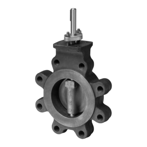
L-Series Butterfly Valves
Instruction Manual
Valve Installation Procedure
Position the connecting pipe flanges in the line to insure proper alignment
prior to valve installation. Spread the pipe flanges apart enough to allow the
valve body to be located between the flanges without actually contacting the
flange surfaces. Exercise particular care in handling the valve so as to prevent
possible damage to the disc or seat faces.
Note: Actuator must be mounted at or above pipe center line for all
actuator types.
1. When installing in Victaulic piping systems, use Victaulic 41 series flange
nipples. 741 flanges not recommended without the use of adapter rings.
2. L-Series Butterfly valves are designed to be installed between ANSI
125/150 flat-faced, raised face, slip-on or weld neck flanges.
3. Do NOT use flange gaskets on L-Series Butterfly valves.
4. For Lug style valves:
a. Place the valve between the flanges.
b. Install all bolts between the valve and the mating flanges. Hand tighten
bolts as necessary.
5. Before completing the tightening of any bolts, the valve should be
centered between the flanges and then carefully opened and closed to
insure free, unobstructed disc movement.
6. Using the sequence, tighten the flange bolts evenly to assure uniform
compression. In assembling flange joints, the resilient seating surface
shall be uniformly compressed.
7. If an actuator is to be operated, electricity should be connected to the
unit in accordance with the local electrical codes.
8. Cycle the valve to the fully open position, then back to the fully closed
position, checking the actuator travel stop settings for proper disc
alignment. The valve should be operated to assure that no binding is
taking place. If no power is available, use the manual handwheel.
9. The valve is now ready for operation.
Max Torque for Bolts
Valve Size Bolt Size Max Torque [ft-lbs]
8” 3/4-10” 120
10”-12” 7/8-9” 200
1
3
2
5
6
7
1
4
5
8
9
10 11
12
12/16 - Subject to change. © Belimo Aircontrols (USA), Inc.
71933-00001.B
