Struers AbraPlan-10 User manual

Manual No.: 15497001
Date of Release 16.03.2005
AbraPlan-10
Instruction Manual

AbraPlan-10
Instruction Manual

AbraPlan-10
Instruction Manual
Table of Contents Page
User’s Guide ..............................................................1
Reference Guide ......................................................25
Quick Reference Guide............................................36
A
lways state Serial No and Voltage/frequency if you have technical questions or when ordering spare parts.
You will find the Serial No. and Voltage on the type plate of the machine itself. We may also need the Date
and Article No of the manual. This information is found on the front cover.
The following restrictions should be observed, as violation of the restrictions may cause cancellation of
Struers legal obligations:
Instruction Manuals: Struers Instruction Manual may only be used in connection with Struers equipment
covered by the Instruction Manual.
Service Manuals: Struers Service Manual may only be used by a trained technician authorised by Struers.
The Service Manual may only be used in connection with Struers equipment covered by the Service Manual.
Struers assumes no responsibility for errors in the manual text/illustrations. The information in this manual is
subject to change without notice. The manual may mention accessories or parts not included in the present
version of the equipment.
The contents of this manual are the property of Struers. Reproduction of any part of this manual without the
written permission of Struers is not allowed.
A
ll rights reserved. © Struers 2005.
Struers A/S
Pederstrupvej 84
DK-2750 Ballerup
Denmark
Telephone +45 44 600 800
Fax +45 44 600 801


AbraPlan-10
Instruction Manual
AbraPlan-10
Safety Precaution Sheet
To be read carefully before use
1. The operator should be fully aware of the use of the machine according
to the Instruction Manual.
2. The machine must be installed in compliance with local safety
regulations.
3. Be aware that the machine’s centre of gravity is located in the upper
half of the machine.
4. Before lifting the machine, ensure that the supplied lifting boom is
securely bolted to the machine.
5. When lifting the machine using a forklift, lift from front or rear - never lift
the machine from the side.
6. When lifting the machine using lifting straps, ensure that the straps are
crossed and do not press on the sides of the machine.
7. The machine must be placed on a safe and stable support, which is
capable of bearing the weight of this machine. Before using the
machine, it must be levelled using the adjustable legs.
8. Be sure that the actual voltage corresponds to the voltage stated on the
side of the machine and that the connections comply with local
regulations. The machine must be earthed.
9. Be aware that when the machine is connected to a compressed air
supply the specimen holder arm moves upwards.
10. Make sure that the specimens in the specimen holder are securely
fixed, and ensure that the securing screws are not sticking out.
11. Keep clear of the grinding stone when operating.

AbraPlan-10
Instruction Manual
12. Always use Safety Goggles when operating the machine.
13. If you observe malfunctions or hear unusual noises - stop the machine
and call technical service.
14. The machine must be disconnected from the mains supply prior to any
service and before connecting or disconnecting the recirculation pump.
15. To achieve maximum safety and lifetime of the machine, use only
original Struers consumables.
The equipment is designed for use with consumables supplied by Struers. If subjected to misuse, improper
installation, alteration, neglect, accident or improper repair, Struers will accept no responsibility for
damage(s) to the user or the equipment.
Dismantling of any part of the equipment, during service or repair, should always be performed by a qualified
technician (electromechanical, electronic, mechanical, pneumatic, etc.)

AbraPlan-10
Instruction Manual
1
User’s Guide
Table of Contents Page
1. Getting Started
Checking the Contents of the Packing Box ..................................... 2
AbraPlan-10............................................................................. 2
Recirculation Cooling Unit (optional)..................................... 2
Placing AbraPlan-10......................................................................... 2
Getting Acquainted with AbraPlan-10............................................ 3
Noise Level........................................................................................ 3
Supplying Power............................................................................... 4
Direction of Rotation ............................................................... 4
Supplying Compressed Air............................................................... 4
Connecting the Recirculation Cooling Unit (accessory).................. 5
Mounting the Grinding Stone/ Diamond Grinding Disc................. 6
Flushing Unit Head.......................................................................... 8
Mounting Stock Removal Sensor (accessory) .................................. 9
Mounting the Water Level Indicator (accessory)............................ 9
2. Basic Operations
Front Panel ..................................................................................... 10
Front Panel Controls ...................................................................... 10
Software Settings............................................................................ 11
Setting the Language ............................................................ 12
Reading the Display ....................................................................... 14
Sleep Mode............................................................................. 15
Changing/Editing Values ...............................................................15
Numeric Values ..................................................................... 15
Text Values ............................................................................ 16
Setting up the Software.................................................................. 17
Dressing Arm Movement ...................................................... 18
Inserting/Removing the Specimen Holder .................................... 18
Inserting the Specimen Holder............................................. 18
Removing the Specimen Holder............................................ 19
Grinding Setup ...............................................................................19
Setting the Process Time ......................................................20
Setting Stock Removal (accessory) ....................................... 20
Setting the Force ................................................................... 21
Cooling Water ........................................................................ 21
Starting the Preparation Process .................................................. 22
Stopping the Preparation Process.................................................. 22
Dressing the Grinding Stone.......................................................... 23
Adjusting the Position of the Dressing Arm ........................ 23
Dressing the Diamond Grinding Disc............................................ 24

AbraPlan-10
Instruction Manual
2
1. Getting Started
In the packing box you should find the following parts:
1 AbraPlan-10
1 Outlet hose (factory mounted)
1 Inlet hose (factory mounted)
2 Hose clamps, 17 mm
1 Drain angle, 900
1 Hose clamp, 35-60 mm
1 Hose for compressed air
2 Hose clamps, 12 mm
1 Hose connection for compressed air
1 Rubber disc 350 mm
1 Flange
1 Bolt M12
1 Allen key 8 mm
1 Set of Instruction Manuals
1 Recirculation Cooling Unit
1 Drain angle, 450
1 Funnel
2 Plastic inserts
AbraPlan-10 should be placed directly on a plane and horizontal
floor, capable of bearing the weight of this machine, please refer
to the Technical Data section.
Checking the Contents of the
Packing Box
A
braPlan-10
Recirculation Cooling Unit
(optional)
Placing AbraPlan-10
AbraPlan-10
Instruction Manual
3
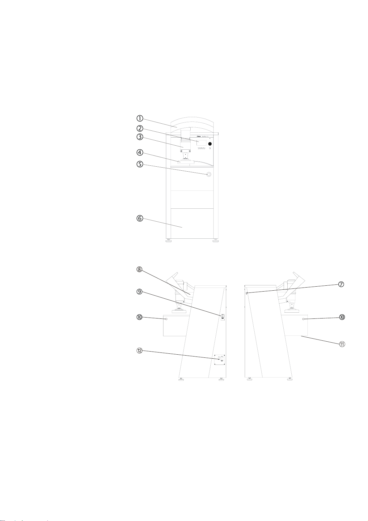
Take a moment to familiarise yourself with the location and
names of the AbraPlan-10 components.
Compressed air inlet
Cast iron beam
Mains power switch
Two-handed start buttons
1 Bottom cover
2Electrical connections
Approx. 68 dB (A) measured during idle running, at the operator's
position in front of the machine.
Getting Acquainted with
AbraPlan-10
Noise Level
Front view
Side views
Shield
Control panel,
(see 2. Basic Operations)
Specimen holder motor
Specimen quick coupling
Emergency Stop
Cover plate for
Recirculation Cooling Unit
AbraPlan-10
Instruction Manual
4
Remove the 4 Allen screws, on the right hand side of the
machine, securing the electrical panel, and let the electrical
panel rest on the tabs.
Lead the cable through the conduit in the panel and connect
the 3 phases and earth according to local regulations.
Where an external recirculation unit is used, connect the
electrical cable from the pump, according to the diagram
located inside the panel.
Check that when the power is turned on the grinding stone/
diamond grinding disc rotates counter-clockwise.
If this is not the case, switch off AbraPlan-10 and unplug the
machine.
Change two of the phases.
Repeat the rotation check.
Connect the compressed air supply to the inlet, located at the
rear of the left-hand side of the machine, using the air hose
and the hose connection delivered with the machine.
Fasten the air hose with a hose clamp.
The pressure supply should be 6-10 bar and can be supplied
either from a central compressor, a portable compressor with a
compressed air reservoir, or a compressed-air bottle. A capacity of
20 l/min at atmospheric pressure is sufficient.
Supplying Power IMPORTANT
Check that the mains supply voltage corresponds to the voltage stated on
the Type Plate (located under the mains switch on the side of the machine).
If the machine is already connected to a mains supply, disconnect this
supply before removing the Allen screws securing the electrical panel.
Direction of Rotation
Supplying Compressed Air
Allen screw
s
AbraPlan-10
Instruction Manual
5
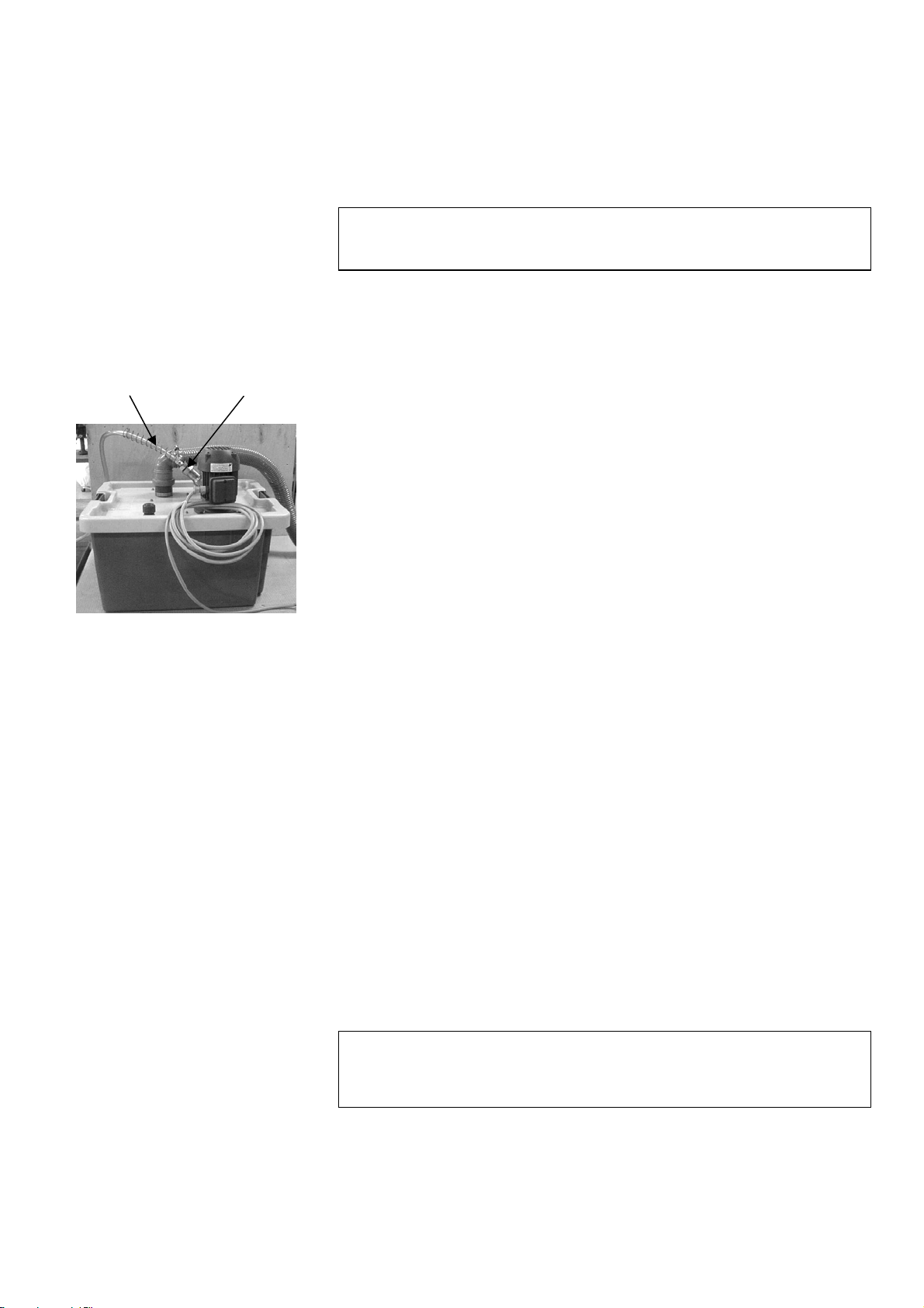
Place the unit where you find it convenient, either inside the
machine or outside, on the left.
Slide the metal spring over the inlet hose (this will prevent
kinks in the hose that could obstruct the flow of water).
Connect the inlet hose from the flushing unit to the pump of
the recirculation unit.
Secure the metal spring in place by turning two coils around
the connector (see illustration).
Cut the drain hose to the correct length, remove
approximately 20 mm of the spring inside the drain hose and
fit the hose over the 900drain angle.
Slide the drain angle over the pipe in the top of the reservoir
lid. (Note: The 450elbow pipe delivered with the Recirculation
Cooling Unit is not used with this machine).
Check that there is a steady fall on the whole course of the
outlet hose.
Open the electrical connections cover
−If mounting inside the machine, lead the cable into the
electrical panel from inside the machine through the rear.
−If mounting outside the machine, lead the cable through
the conduit in the panel.
Now connect the cable to the AbraPlan-10 using the terminal
connectors in the electrical panel.
Check that when the power is turned on, the pump rotates in
the direction indicated by the arrow on the top of the pump. If
this is not the case, change 2 of the electrical phases.
Replace the cover to the electrical connections.
If mounting inside the machine, remove the front cover and
place the tank on the trolley.
Place a disposable plastic insert in the tank and fold it over
the rim.
Fill the tank with 29.1 l water and 900 ml Struers Additive
for Cooling Fluid.
The water level should be 8-10 cm below the upper rim of the
tank.
Connecting the Recirculation
Cooling Unit (accessory)
Warning
Disconnect the machine from the mains power supply
before connecting or disconnecting the recirculation pump.
IMPORTANT
Too high a level of coolant in the tank might damage the pump. To avoid
this, place the disposable insert so that the pre-punched hole is in front of
the overflow aperture in the tank.
Metal Spring Connector

AbraPlan-10
Instruction Manual
6
Fit the tank lid and sieve.
Move the unit into place and lead the outlet and overflow
drain hoses into the cooling water tank. Adjust the lengths if
necessary.
If mounting inside, replace the front cover.
Flushing unit head
Securing finger screws
Stone guard
Dressing arm
Ensure that the sample motor is fully raised, and lift the
shield to gain access to the grinding area.
Make sure that the dressing arm is located in its storage
position (on the left-hand side).
Lift the flushing unit head and, using its built-in magnet,
attach it to the sample motor mounting arm.
Move the sliding cover on the stone guard across until it is
free at both ends.
Unscrew the 2 finger screws (located on the right-hand side)
Use both the handle and the flushing unit connection to lift
the stone guard up and away to the right.
IMPORTANT
Always maintain the correct concentration of Struers Additive in the cooling
water (percentage stated on the Additive container).
Remember to top up with Struers Additive each time you refill with water.
Mounting the Grinding Stone/
Diamond Grinding Disc IMPORTANT
Make sure that the grinding stone/diamond grinding disc is intact.
The stone/disc must be dry when mounted and the flange should be
clean and smooth.

AbraPlan-10
Instruction Manual
7
Assemble the grinding stone/ diamond grinding disc on the
flange as illustrated:
Motor Flange
Rubber disk
Grinding stone/ diamond grinding disc
Securing flange and cardboard washer
Securing bolt
Mount the bolt and fasten firmly.
Replace the stone guard and secure it with the 2 finger
screws.
IMPORTANT
Do not over tighten the securing bolt as this may damage the
grinding stone/disc.
IMPORTANT
Remember to re-attach the flushing unit head.
Remember to raise the dressing arm to the top of its travel.

AbraPlan-10
Instruction Manual
8
When attached to its mounting (as illustrated), the flushing unit
supplies water/coolant to the grinding stone/ diamond grinding
disc during the grinding and dressing processes. However, the
flushing unit can be removed from the mounting and used to hose
down the grinding area and samples etc. To do this:
Squeeze in and hold the clamp buttons (illustrated by arrows)
to cut-off the water/coolant flow.
Press F1 to start the pump.
Lift the flushing unit free of its mounting.
Direct the flushing unit in the desired direction and release
the clamp buttons.
Press F1 to stop the pump.
Reinsert the flushing unit in its mounting.
If the grinding/dressing process is not active, a water/coolant flow
can be achieved by pressing F1 when the GRINDING or
DRESSING Menus are displayed.
Flushing Unit Head
AbraPlan-10
Instruction Manual
9
Disconnect main power.
Connect the plug on the removal sensor with the plug located
on the inside of the control panel.
Take the removal sensor and gently slide it up in the hole
located in the bottom of the cast iron beam.
Let the bracket slide over the factory installed bracket.
From the left, slide the two screws through the brackets, and
tighten them with a 10 mm spanner.
Reconnect the main power and follow the instructions on the
display, using the tools supplied and the calibrating sticks.
Switch the machine off.
Pull out the recirculation unit.
Remove the pump, drain hose and the top cover.
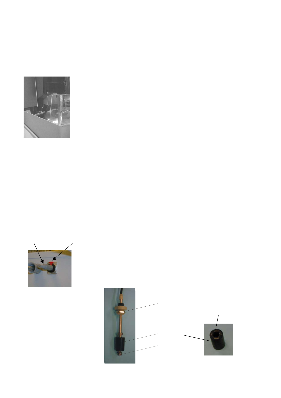
Remove the red cover from the hole for the sensor or remove
the existing Water Level Indicator.
Remove the locking nut on the bottom of the sensor and slide
off the black float.
Mount the new Water Level Sensor on the recirculation unit
cover and secure using the nut supplied (flat side of nut up).
Replace the float (with the clear surface up) and secure the
locking nut in place.
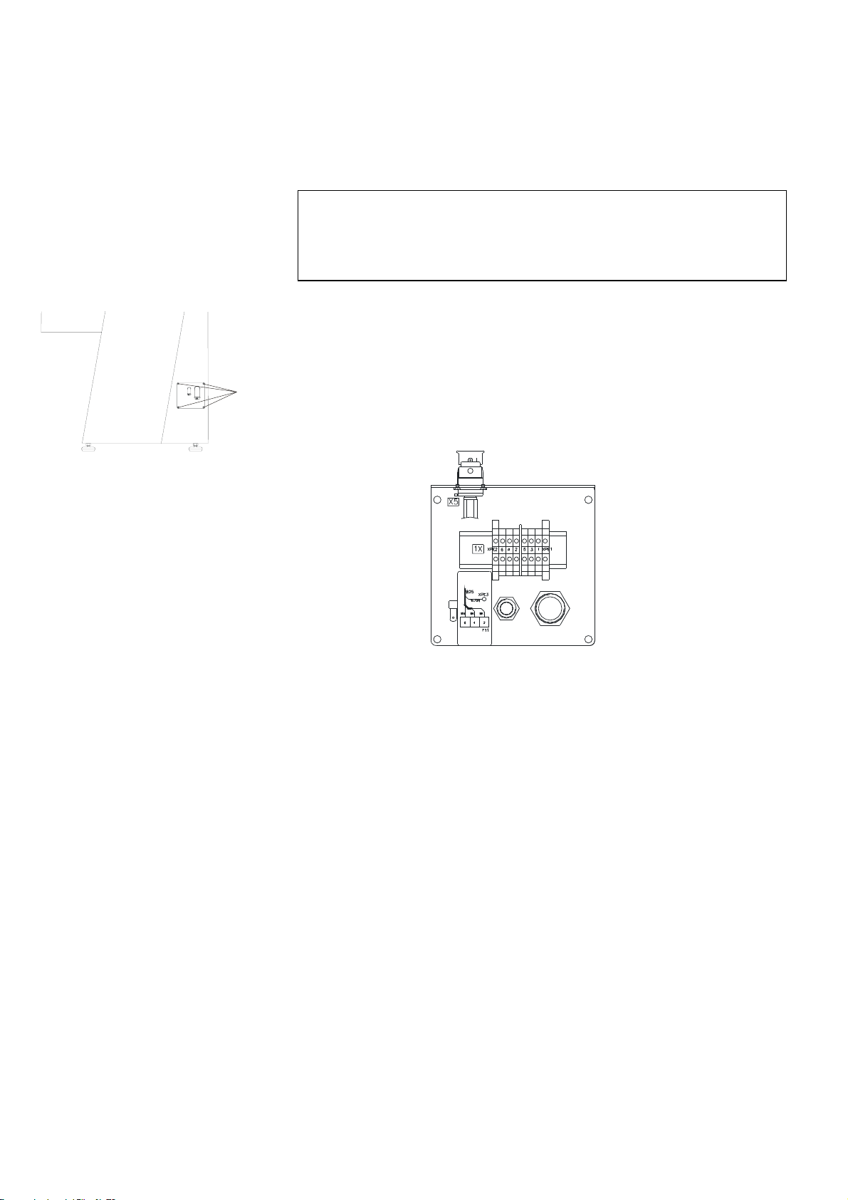
On the right hand side of the machine, remove the 4 Allen
screws securing the electrical panel, and let the electrical
panel hang on the two tabs (as illustrated in Supplying
Power).
Remove the dummy jack plug located on the electrical panel
by pressing down the red tab.
Plug in the jack plug from the sensor.
Reassemble the recirculation unit and slide it back into
position.
Replace the front cover.
Switch the machine on.
Nut
Black float
Locking nut
Mounting the Stock Removal
Sensor (accessory)
Mounting the Water Level
Sensor (accessory)
Clear surface
Dummy jack Red tab

AbraPlan-10
Instruction Manual
10
2. Basic Operations
AbraPlan-10
Power
F3
F1 Esc
F4
F2
Name Key Function Name Key Function
FUNCTION
KEY
F1 Controls for various purposes.
See the bottom line of the
individual screens.
Push/Turn
Knob Used for entering and changing
parameters.
Combined cursor and enter key.
FUNCTION
KEY
F2 Controls for various purposes.
See the bottom line of the
individual screens.
Esc Esc Leaves the present menu or
aborts functions/changes.
FUNCTION
KEY
F3 Controls for various purposes.
See the bottom line of the
individual screens.
STOP o Stops the preparation process.
FUNCTION
KEY
F4 Controls for various purposes.
See the bottom line of the
individual screens.
EMERGENCY
STOP
The EMERGENCY STOP is
located on the front of the
machine.
- Push the red button to stop.
- Pull the red button to release.
MAIN
SWITCH
The main switch is located on
the right side of the machine.
Front Panel
Front Panel Controls
↵
AbraPlan-10
Instruction Manual
11
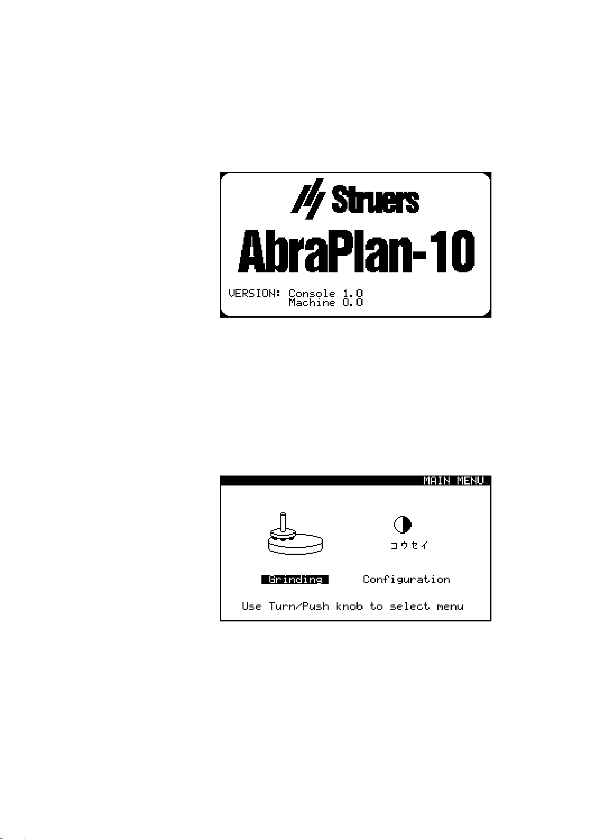
Switch on the power at the main switch located at the right hand
side of the machine. The following display will appear briefly:
The display will then change to the last screen shown before
AbraPlan-10 was switched off. When switching on AbraPlan-10
for the first time, the MAIN MENU display will appear. If the
heading in the display is different, press Esc, until the MAIN
MENU appears.
The MAIN MENU is the highest level in the menu structure.
From this menu, you can enter the configuration menu and
grinding process menu.
Software Settings

AbraPlan-10
Instruction Manual
12
Before continuing, we recommend that you select the language
that best suits you.
D
Turn knob to select CONFIGURATION
D
Push knob to activate the
CONFIGURATION Menu
D
D
Turn knob to select Language.
D
Push knob to activate the Language pop-up
menu.
D
D
Turn knob to select the language you
prefer.
D
Setting the Language

AbraPlan-10
Instruction Manual
13
Push knob to accept the language.
The CONFIGURATION Menu now appears in the
language you have chosen.
Esc Press Esc to return to the MAIN MENU.
AbraPlan-10
Instruction Manual
14
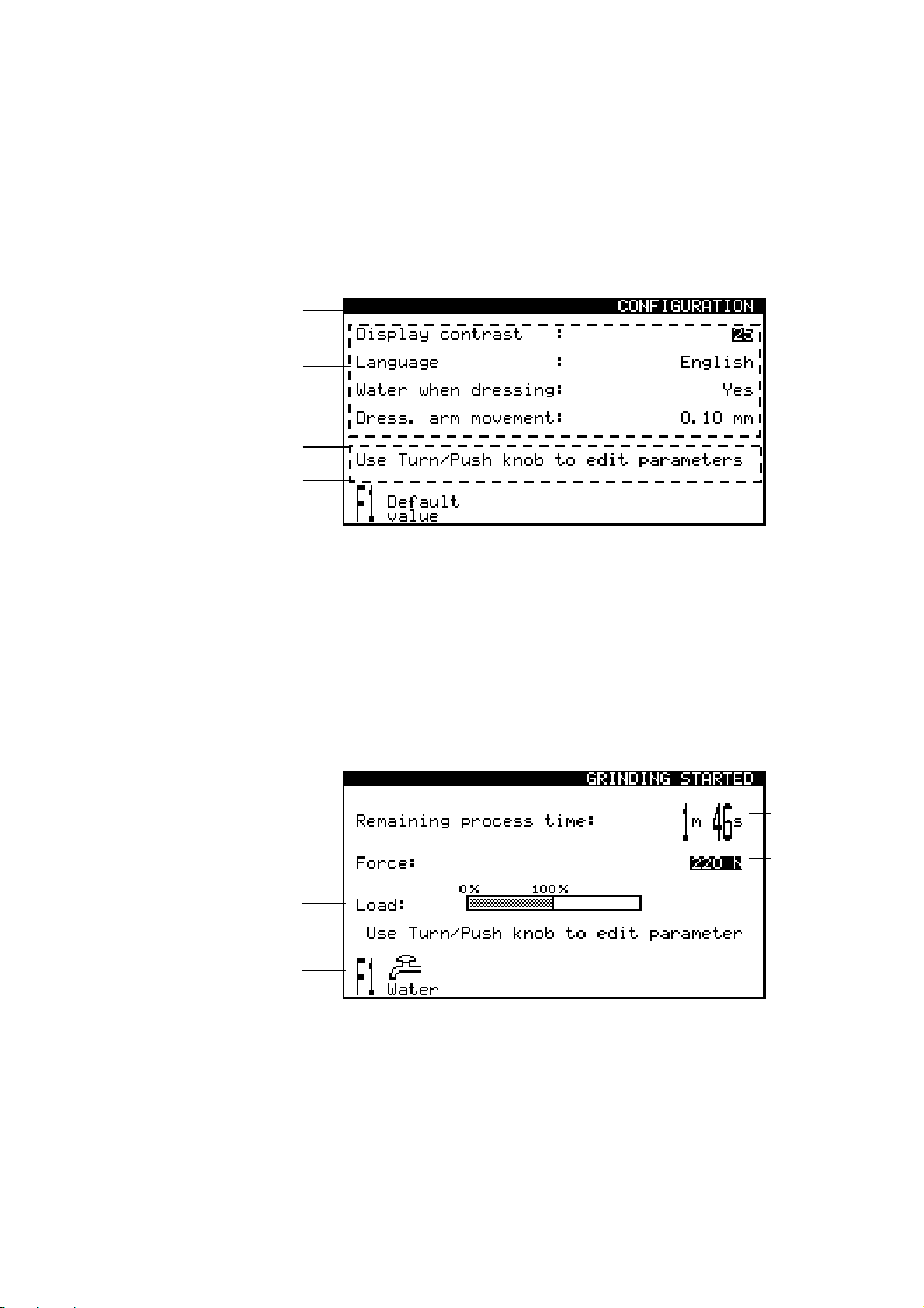
The display is primarily divided into 4 areas. The position of these
areas and the information they contain are explained in the
illustration below, which uses the CONFIGURATION Menu as an
example:
A Heading: this tells you where you are in the software.
B Information fields: these will either be numerical values or
text fields providing information associated with the process
shown in the heading. The inverted text shows the cursor
position.
C Help text: helpful hints to allow you to continue.
DFunction key options: the functions of these change with the
window displayed.
During the grinding process the screen could look as follows:
A Grinding time remaining
B Force applied on specimen holder
C Load on main motor
D Function(s) selectable during process
Reading the Display
B
A
A
B
D
C
C
D
Table of contents
Languages:
Other Struers Grinder manuals


