8.Ifmachinerunsclockwise(backwards),itmustberewiredtocorrectrotation,otherwiseseriousirreparable
damage may occur to grinding components.
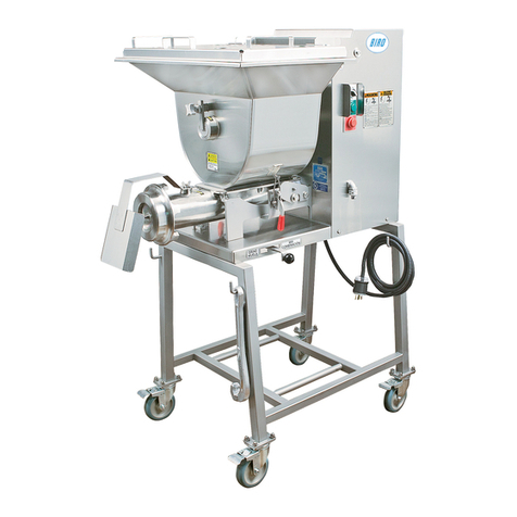
9. Check that the grinding bowl is properly seated and that the bowl lock assembly is tight. Insert worm
assemblyintogrindingbowl,placeknife(sharpedgesout)ontothesquareendoftheknifedrivepin.The
breaker plate slides over the worm knife drive pin, and is held from rotating by a pin in the grinding bowl.
Put on the retaining ring.
ONLY HAND TIGHTEN RETAINING RING
For best results, use knife and plate as a set. Do not operate machine for any period of time without
product in the grinding bowl. This will cause heating and dulling of the knife and plate.
10. Check placement of all warning labels and Manual. Machine is now ready for trained operators to process
product.
11. Contact your local Distributor or BIRO directly if you have any questions or problems with the
installation or operation of this machine.
MOTOR WIRING AND ELECTRICAL REQUIREMENTS
(1)Interchangeofcurrentismadeinmotoroutletbox.Leadsareproperlymarked.Changinginstructions
areonthemotorplateormotoroutletbox.Electricalcontactormountedonmachineframemustalsobe
changed to match motor voltage.
(2)Allgrindersarewiredforthevoltageasordered.Besuremotorspecications(voltage,cycle,phase)
matchpowersupplyline.Besurelinevoltageisuptospecication.
(3)ElectricalconnectionstobeinaccordancewithsafetycodesandNationalElectricalCode.
(4)Ratedvoltageoftheunitshallbeidenticalwithfullsupplyvoltage.
(5)Voltagedroponthesupplylineshallnotexceed10%offullsupplyvoltage.
(6)Thefeederlineconductorsizeintheracewayfromthebranchcircuittotheunitmustbecorrectto
assure adequate voltage under heavy starting and short overload conditions.
(7)TheBIROManufacturingCompanyisnotresponsibleforpermanentwiring,connectionor
installation.
NOTE TO OWNER AND ELECTRICIAN: IF THIS MACHINE IS NOT CORD
AND PLUG CONNECTED TO THE ELECTRICAL SUPPLY SOURCE, THEN IT
SHOULD BE EQUIPPED WITH, OR CONNECTED TO, A LOCKABLE,
MANUALLY-OPERATED DISCONNECT SWITCH (OSHA 1010.147).
4
UNCRATING AND SET UP - CONTINUED
ELECTRICAL CONTACTORS
(1)Most1HPmotorsaredualvoltageandcanbechangedaccordingtowiringdiagramonmotornameplate.
(2)Besurecontactorvoltagematchesvoltageofmotor.
(3)Failure to use proper contactor for motor voltage will cause irreparable damage to contactor.
(4)Installproperplugonpowercordforvoltageused.
A. Item No. C903 Contactor LS07-110V
1 HP, 104-60-1
1 HP, 115-60-1
1 HP, 380/415/440-50/60-3 w/ 56110 transformer
B. Item No. C903-1 Contactor LS07-220V
1 HP, 220-50/60-3
1 HP, 208/230-60-1
1 HP, 240-50-1
