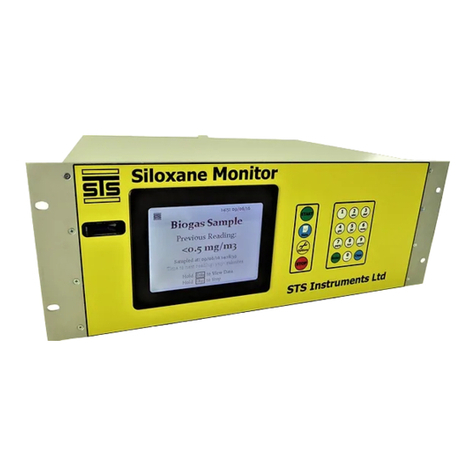
STS Instruments Siloxane User manual

STS Instruments Ltd,
Testing &
Commissioning Manual
201
8
SILOXANE MONITO MANUAL
STS INST UMENTS LTD COPY IGHT 2018
STS INST UMENTS LTD
|
www.siloxanemonitoring.com

1
16/08/2017, STS Instruments Ltd, Testing & Commissioning Manual
TABLE OF CONTENTS
1.0 Manual Guide ..................................................................................................... 2
1.1
Document Version ....................................................................................... 2
1.2
Symbols Used ............................................................................................. 2
1.3
Safety Information ....................................................................................... 3
1.4
Environmental parameters ............................................................................. 4
1.5
Instrumentation Safety Symbols ...................................................................... 4
2.0
Overview ...................................................................................................... 5
2.1
Instrument schematic .................................................................................. 5
2.2
Samplings schematic ..................................................................................... 6
3.0
Sampling system gas testing ............................................................................... 7
3.1
Features.................................................................................................... 7
3.1.1
4-20mA data line ...................................................................................... 7
3.1.2
emote Data access .................................................................................. 8
3.1.3
Solenoid Switching valves............................................................................ 8
3.1.4 Kiosk enclosure fan control ............................................................................ 8
3.1.5 Heated line ............................................................................................... 8
3.1.6 Automated Water Trap ................................................................................. 8
3.1.7 Coalescing Filter ......................................................................................... 8
3.1.8
Ancillary Control Box ................................................................................. 9
3.1.9 Nitrogen connection..................................................................................... 9
4.0
Cabinet Layout .............................................................................................. 10
4.1
Ventilation ................................................................................................ 12
4.2
Kiosk Images ............................................................................................. 13
4.3
Instrument Connections ................................................................................ 14
4.3.1
Biogas Connection ................................................................................... 14
4.3.2
Nitrogen Connection ................................................................................ 14
4.3.3
Instrument Air Intake ................................................................................ 14
4.3.4
Instument air Exhaust ............................................................................... 14
4.3.5
Vent .................................................................................................... 14
4.3.6
Power ................................................................................................... 14
4.3.7
DataComms ............................................................................................ 15
4.3.8
Ancillary Box .......................................................................................... 16
4.4
Circuit Board Connector information ............................................................... 17
4.4.1 Main Silox PCB Layout ................................................................................. 17
4.4.2 MCU PCB .................................................................................................. 19
5.0 Operation ........................................................................................................ 20

2
16/08/2017, STS Instruments Ltd, Testing & Commissioning Manual
5.1 Turn On ........................................................................................................ 20
5.2 Set Time /Date ............................................................................................... 21
5.3 Starting a eading cycle .................................................................................... 22
5.4 Setting up Manifold switching ............................................................................. 24
5.5 emote Data comms set up ................................................................................ 26
6.0
Commissioning Checklist .................................................................................. 27
7.0
Fault Identification........................................................................................ 29
7.1
Instrument Error codes ................................................................................ 29
7.2
4-20mA emote Data Error codes ................................................................... 29
8.0
Appendices .................................................................................................. 30
1.0 MANUAL GUIDE
1.1 DOCUMENT VE SION
Issued by
Author
Issue Date
evision Number
STS
Jim Ward
18/10
/2016
1.0
STS
Jim Ward
20/10/201
6
1.1
Final
STS
Jim Ward
26/05/2017
1.2
4
-
20 Error codes P29

STS
Jim Ward
26/05/2017
1.3 N2 Cylinder Connection
STS
Jim Ward
16/08/2017
1.4 Amended kiosk layout P12, added kiosk gas flow
diagrams to appendices P33
1.2 SYMBOLS USED
Safety Warning
Identifies potential
hazards to either
the user or the
installation.
Failure to follow this
information may result in
physical injury that in some
cases could be fatal, cause
irrevocable damage to the
instrument or damage to the
environment.
Electrical Hazard
Identifies specific
electrical hazards
to the user.
Failure to follow this
information may result in
physical injury that in some
cases could be fatal or may
cause irrevocable damage to
the instrument.

3
16/08/2017, STS Instruments Ltd, Testing & Commissioning Manual
Notes
Identifies areas
where clarification
may be required.
1.3 SAFETY INFO MATION
Should at any point you require additional help or information on the use or installation
of the system please contact STS directly at: sales@safetrainingsystems.com or +44 (0) 1344
483563
The STS Siloxane Monitor operates from a 110V mains supply, the instrument case
should not therefore be opened without having first isolated the power supply and disconnected
the kettle lead form the rear of the instrument. The high voltage section of the instrument is
protected by clear cover – this should not be removed unless necessary- having followed the above
instructions. FAILU E TO ISOLATE THE SUPPLY MAY ESULT IN ELECT IC SHOCK.
It is the responsibility of the owner of the instrument to complete a risk assessment on its
installation, operation and servicing before being commissioned for use.
Inhalation of gases may be harmful to health, it is the responsibility of the operator to ensure they
have adequate training in the safety aspects of handling biogas/landfill gas and that they follow
appropriate procedures at all times. The vent/exhaust form the instrument must be piped to an
area designated safe to discharge to atmosphere- a flame arrestor may be required to be fitted.
Installation and Maintenance of the unit should only be carried out by suitably trained personnel
according to the applicable code of practice.
Maintenance should be carried out only using STS approved replacement parts and components –
use of substitutes will invalidate the warranty and may be hazardous to both operator and
instrument.
No alterations should be made to the instrument or its ancillary components.
Failure to comply with the instructions in this manual could result in injury to the user.
The instrument captures fuel gas any work associated with the instrument must be carried out by a
class of person competent and certified to do so.

4
16/08/2017, STS Instruments Ltd, Testing & Commissioning Manual
1.4 ENVI ONMENTAL PA AMETE S
•The Siloxane Monitor is not weatherproof and must be housed in a suitable kiosk or cabinet
if sited outside of a building
•If siting inside a building consideration should be given to the local conditions as regards to
dust, moisture and ventilation the Monitor is available supplied in a 19” rack case suitable
for indoor use with inbuilt thermostatically controlled extraction fans.
•The monitor is suitable for use between 5C and 45C without additional cooling/heating
required.
•Gas supply to the instrument should be at a minimum of 200mbar
•Adequate ventilation/air passage around the instrument should be provided.
1.5 INST UMENTATION SAFETY SYMBOLS
Caution
Electrical Hazard
Earth Point
Hot Surface
Should at any point you require additional help or information on the safe installation or
use of the system please contact STS immediately at: sales@safetrainingsystems.com or +44
(0) 1344 483563

5
16/08/2017, STS Instruments Ltd, Testing & Commissioning Manual
2.0 OVE VIEW
2.1 INST UMENT SCHEMATIC

6
16/08/2017, STS Instruments Ltd, Testing & Commissioning Manual
Biogas is supplied to the instrument via a sampling system that removes water and particulates.
The instrument has been assessed in accordance with IGE S 25 for potential leakage risk and
development of explosive atmospheric conditions internal to the instrument.
The design of the instrument is such that failure of any internal joint inside the instrument cannot
give rise to an explosive atmosphere inside the instrument. Nevertheless prior to energising the
instrument a pressure drop assessment including the instrument shall be performed. This test shall
be performed in accordance with IGE UP1B and include the instrument.
(to 35mb with 1 minute temperature stabilisation followed by a 2 minute tightness test). There
shall be no discernible pressure drop over 2 minutes.
If there is a pressure drop then the instrument shall be isolated and the case shall be removed and
the internal elements inspected for damage. If the leakage cannot be corrected the instrument
shall be removed for factory inspection and correction.
2.2 SAMPLINGS SCHEMATIC
Biogas is sampled by taking samples of raw and or treated biogas from the main gas pipework used
to supply the biogas engine.
The sampling arrangement may be single port or multiport, so that the instrument is capable of
sampling raw untreated gas, partially treated gas and treated gas prior to combustion in the biogas
engine.
The sample lines should be connected into purge points by means of a reducing T and additional
isolation valve. The sample points shall be installed so that the purge point on the main gas
pipeline remains usable for nitrogen or air purging.
The sample points shall be provided with individual isolation and test points to enable sample line
isolation and to enable sample line purging.
Sample pipelines shall be mounted on robust racking.
Sample lines shall be provided with trace heating and lagging from the instrument to the sample
point. Electrical power for the trace heating shall be taken from the instrument supply.
The sample line pressure shall be tested and a regulator selected to ensure an instrument sampling
system pressure does not exceed 35mb. If the system pressure has been declared by the operator
the installer shall nevertheless verify the site system pressure and selected regulator and ensure
that compliance with a 35mb inlet pressure is achieved.

7
16/08/2017, STS Instruments Ltd, Testing & Commissioning Manual
The sampling pipework is directed to solenoid valves these are under the control of the instrument
which will select the sample it is measuring. The installer shall ensure that each sampling point is
directed to the correct solenoid in the sampling system.
Immediately after the solenoid valves the biogas is sent to a pressure regulator. Normally the
pressure regulator has been preselected for the site based on operator biogas pressure data. The
Installer is required to verify the pressure immediately downstream of the gas pressure regulator.
A water trap device is provided immediately after the regulator, the water trap is provided with an
auto drain point. The auto drain is a potential methane release point and must be terminated
outside of any enclosed space, and marked with a warning label to indicate that it could release
methane.
A coalescing filter is fitted in line after the water trap to remove any remaining moisture from the
gas stream, this is a sealed unit with no release point.
After the coalescer some installations are provided with a flame arrester, this is an optional feature
selected by some operators. If a flame arrester has been provided the installer should ensure that it
does not excessively restrict gas flow during commissioning.
The final treatment stage in the sampling system is a particulate filter(within the instrument), this
does not require further checking during installation.
3.0 SAMPLING SYSTEM GAS TESTING
The siloxane instrument has an isolation valve immediately before the instrument, and immediately
after the solenoid valves.
The sampling system downstream of the gas regulator shall be tested in accordance with IGE UP1B.
(to 35mb with 1 minute temperature stabilisation followed by a 2 minute tightness test). There
shall be no discernible pressure drop over 2 minutes.
The sampling pipework shall be tested in accordance with IGE UP 1 Ed 2 except hydrostatic testing
shall not be used.
The testing shall be performed without trace heating being energised. For most installations the
stabilisation period will be 10 minutes with a strength test duration (STD) of 5 minutes, the
maximum % drop will be 20% of the Strength Test Pressure (STP)
With the trace heating energised the installer shall verify the temperature of the sample lines. The
minimum temperature for acceptable operation is 60 deg C.
3.1 FEATU ES
3.1.1 4-20mA DATA LINE
Provided for the transfer of data to a 3
rd
party system.
On the rear of the instrument there is an 12-way connector (colour coded Blue) which is for
connection of the 4-20mV data lines. The instrument supports up to 4 data parameters.

8
16/08/2017, STS Instruments Ltd, Testing & Commissioning Manual
3.1.2 EMOTE DATA ACCESS
A data service accessible from any internet connection where individual or groups of monitors can
be viewed to see current and trend data on a secure website. Email alerts to set alarm thresholds
may be configured and data downloaded as CSV files.
Where specified a GSM data communications box is fitted which takes the 4-20mV inputs form the
instrument. The system consists of a communications box that houses the GSM transmitter and
logging software and a secondary UPS box which will keep reporting after loss of power. Although
the instrument will automatically shut down in safe mode should the power fail the telemetry will
then be able to alert the operator that the instrument power has failed. The UPS box can be
supplied from either 110V or 240V.
Danger of electrocution – disconnect UPS from mains supply before opening box.
3.1.3 SOLENOID SWITCHING VALVES
Provided to allow a number of different sampling points to be monitored automatically.
The instrument may have up to 3 different sample line feeds. These are brought into the
instrument as separate lines to a series of switching solenoid valves. The valves are controlled
from the switching schedule on the instrument.
3.1.4 KIOSK ENCLOSU E FAN CONT OL
For temperature control to prevent overheating of the instrument in hot environments.
3.1.5 HEATED LINE
Used where pipework is run outside of buildings to prevent diurnal fluctuation due to condensation
of Siloxanes into pipework – typically 110V, 16A.
3.1.6 AUTOMATED WATE T AP
The automated water trap is designed to remove excess moisture form the gas stream before
entering the instrument. The trap should be located such that it is vertically mounted by means of
the fixing bracket at the top of the unit. The trap is powered and activated by the Siloxane
Monitor via the ancillary control box.
3.1.7 COALESCING FILTE
The automated trap will activate when the internal float rises sufficiently to trigger the
solenoid valve to be opened. The fluid is evacuated from the reservoir by the incoming gas
pressure until the float returns to the rest position which closes the solenoid.

9
16/08/2017, STS Instruments Ltd, Testing & Commissioning Manual
The coalescing trap is designed to remove very fine water particles from the gas stream, it should
be situated in line between the water trap and the flame arrestor (where fitted). The trap should
be secured vertically by means of the fitting at the top of the unit This trap does not drain and
should not have any visible water inside. If there is water present, the filter element should be
changed immediately and the auto drain trap should also be checked to ensure its correct function.
3.1.8 ANCILLA Y CONT OL BOX
Connector colour coded ed.
•Sample line switching to solenoids
•24V supply to Water trap
•Exterior cabinet fan supply
3.1.9 NIT OGEN CONNECTION
Before operation the Nitrogen cylinder must be connected and turned on. The Nitrogen is required
to be set to 1.0 Bar.
Nitrogen should be of Technical Grade 99.999% purity. A standard N2 regulator should be fitted to
the cylinder and the Special adaptor fitting supplied by STS used to connect the ¼” pipe.
The Coalescing filter should be changed annually – once replaced ensure that the vessel
is pressure tested for leaks before setting the system live.

10
16/08/2017, STS Instruments Ltd, Testing & Commissioning Manual
4.0 CABINET LAYOUT

11
16/08/2017, STS Instruments Ltd, Testing & Commissioning Manual
The siloxane instrument is designed for installation in a building or kiosk, the instrument and
sampling system are available pre-mounted in a weather proof container, the container is provided
with all necessary vent and drain and power connections.
If the instrument is being installed in a building or kiosk that contains other equipment, then it
should be provided with:
Approved vent connections
Electrical Power
Nitrogen Purge connection
Biogas sampling connections
Drain connection

12
16/08/2017, STS Instruments Ltd, Testing & Commissioning Manual
4.1 VENTILATION
The instrument ventilation is designed to prevent any risk of a build-up of methane inside the
instrument, the correct provision of the vents is necessary to ensure that the instrument remains
safe.
The ventilation shall be configured so that the air supply to the instrument is drawn through a grill
from a horizontal duct laid with a 3 degree fall away from the instrument.
The discharge vent connection shall be discharged outside of the building at a safe location, the
discharge vent shall be terminated with a bend to prevent wind driven rain from entering the duct.

13
16/08/2017, STS Instruments Ltd, Testing & Commissioning Manual
4.2 KIOSK IMAGES

14
16/08/2017, STS Instruments Ltd, Testing & Commissioning Manual
4.3 INST UMENT CONNECTIONS
4.3.1 BIOGAS CONNECTION
Connection to the instrument is by way of a ¼” swagelok bulkhead fitting with retaining lug.
Label: Biogas IN
4.3.2 NIT OGEN CONNECTION
Connection to the instrument is by way of a ¼” swagelok bulkhead fitting with retaining lug.
Label: N2 IN
4.3.3 INST UMENT AI INTAKE
The spigot on the rear of the instrument case has a 50mm OD diameter suitable to connect 50mm
ID flexible tubing to it.
Label: Instrument Air Intake
4.3.4 INSTUMENT AI EXHAUST
The spigot on the rear of the instrument case has a 50mm OD diameter suitable to connect 50mm
ID flexible tubing to it.
Label: Instrument Air Exhaust
4.3.5 VENT
Connection to the instrument is by way of a ¼” swagelok bulkhead fitting with retaining lug.
Label: VENT
4.3.6 POWE
A 3pin kettle lead receptacle with on off switch is located on the rear panel.
Label: POWE 110V

15
16/08/2017, STS Instruments Ltd, Testing & Commissioning Manual
Danger of Electrocution Switch off and isolate from the mains supply before opening the
case.
4.3.7 DATACOMMS
A 12 way circular connector is provided for 4-20mV data output. Colour coded BLUE.
Label: DATA COMMS
PCB Connectors to ear Connector:
ear
PIN
PCB
Label
1
CONN25 PIN 1
Vcc +12V
2
CONN4 PIN 1
M1 +
3
CONN4 PIN 2
M1 Iout
4
CONN5 PIN 1
M2 +
5
CONN5 PIN 2
M2 Iout
6
CONN6 PIN 1
M3 +
7
CONN6 PIN 2
M3 Iout
8
CONN7 PIN 1
M4 +
9
CONN7 PIN 2
M4 Iout
10
CONN25 PIN 2
GND
These are uniquely wired.
ear plug connector to Metron2 Plug Cable:
ear PIN
Cable Wire
1
ed
2
Purple
3
White
4
Grey
5
Yellow
6
Brown
7
Orange
8
Green
9
Blue
10
Black
Using a 10way Shielded Multicore Cable
Cable to Metron2 Terminals
Cable Wire
Metron2
ed
Power +
Purple
Input 1 +V
White
Input 1 IN

16
16/08/2017, STS Instruments Ltd, Testing & Commissioning Manual
Grey
Input 2 +V
Yellow
Input 2 IN
Brown
Input 3 +V
Orange
Input 3 IN
Green
Input 4 +V
Blue
Input 4 IN
Black
Power
-
4.3.8 ANCILLA Y BOX
A 12 way circular connector is provided for ancillary switching services, cabinet fan and water trap
power supply. Colour coded ED.
Label: ANCILLA Y
PCB Connectors to ear Connector:
ear PIN
PCB
Label
1
CONN20 PIN 1
V+ 24V
2
CONN20 PIN 7
WTSense
3
CONN20
PIN 8
V1
4
CONN20 PIN 9
V2
5
CONN20 PIN 10
V3
6
CONN20 PIN 11
V4
7
CONN20 PIN 12
VWT
8
CONN20 PIN 13
SPA E
9
CONN20 PIN 14
SPA E
10
CONN20 PIN 15
GND
SHEILD
CONN20 PIN 16
GND
These are uniquely wired.
ear plug connector to Manifold Switching Box Plug:
ear PIN
Cable Wire
1
ed
2
Purple
3
White
4
Grey
5
Yellow
6
Brown
7
Orange
8
Green
9
Blue
10
Black
Using a 10way Shielded Multicore Cable

17
16/08/2017, STS Instruments Ltd, Testing & Commissioning Manual
Manifold Socket to Jumpers:
ear PIN
Cable Wire
Manifold Jumper
Position
1
ed
1
2
Purple
7
3
White
8
4
Grey
9
5
Yellow
10
6
Brown
11
7
Orange
12
8
Green
SPA E
9
Blue
SPA E
10
Black
13
4.4 CI CUIT BOA D CONNECTO INFO MATION
4.4.1 MAIN SILOX PCB LAYOUT
See Appendix for Enlarged Diagram
Connectors:
1: 24V supply to PCB from Power Supply
2: Infrared Detector

18
16/08/2017, STS Instruments Ltd, Testing & Commissioning Manual
3: Infrared Source
4: Not used
5: Case Fans
6: Connection to MCU PCB
7: Permeation Oven Cut out sensor
8: Concentrator Oven Cut out sensor
9: Concentrator Temperature Sensor
10: Permeation Oven Temperature Sensor
11: Solenoid Valve 1
12: Solenoid Valve 2
13: Solenoid Valve 3
14: Solenoid Valve 4
15: Concentrator Fan
20: Connection to Auxillary control box
25: Heat Sink cooling Fan
M1: Mains 110V to PCB
M2: Mains 110V to Power Supply
M3: Mains to Pump
M4: Mains to Permeation Oven Heaters
M5: Mains to Concentrator Heater
Danger of Electrocution Switch off and isolate from the mains supply before opening the
case.
The Silox PCB has a clear plastic shield over the Mains power section to protect users.
THIS SHIELD MUST NOT BE EMOVED UNLESS THE INST UMENT HAS BEEN ISOLATED F OM THE
MAINS SUPPLY AND DISCONNECTED

19
16/08/2017, STS Instruments Ltd, Testing & Commissioning Manual
4.4.2 MCU PCB
See appendix for enlarged diagram
1: Not USed
2: Membrane Keypad Connection
3: Connection to Main Silox PCB
4: 4-20mA Channel 1
5: 4-20mA Channel 2
6: 4-20mA Channel 3
7: 4-20mA Error Line
Other manuals for Siloxane
4
Table of contents
Other STS Instruments Measuring Instrument manuals