Stuart Turner PH 45 TS S Guide

Installation, Operation & Maintenance
Instructions
Please leave this instruction booklet with the home owner as it contains
important guarantee, maintenance and safety information
Read this manual carefully before commencing installation.
This manual covers the following products:
PH 45 TS S
Pt. No. 46628 PH 45 TS S
Pt. No. 46629
CE compliant product
PH 45 TS S
Pt. No. 46632

- 2 -
Cont ...
INDEX . . . . . . . . . . . . . . . . . Page No
Application. . . . . . . . . . . . . . . . . . . . . . . . . . 2
Product Description. . . . . . . . . . . . . . . . . . . 3
Limits of Application. . . . . . . . . . . . . . . . . . . 4
Technical Specification . . . . . . . . . . . . . . . . 4
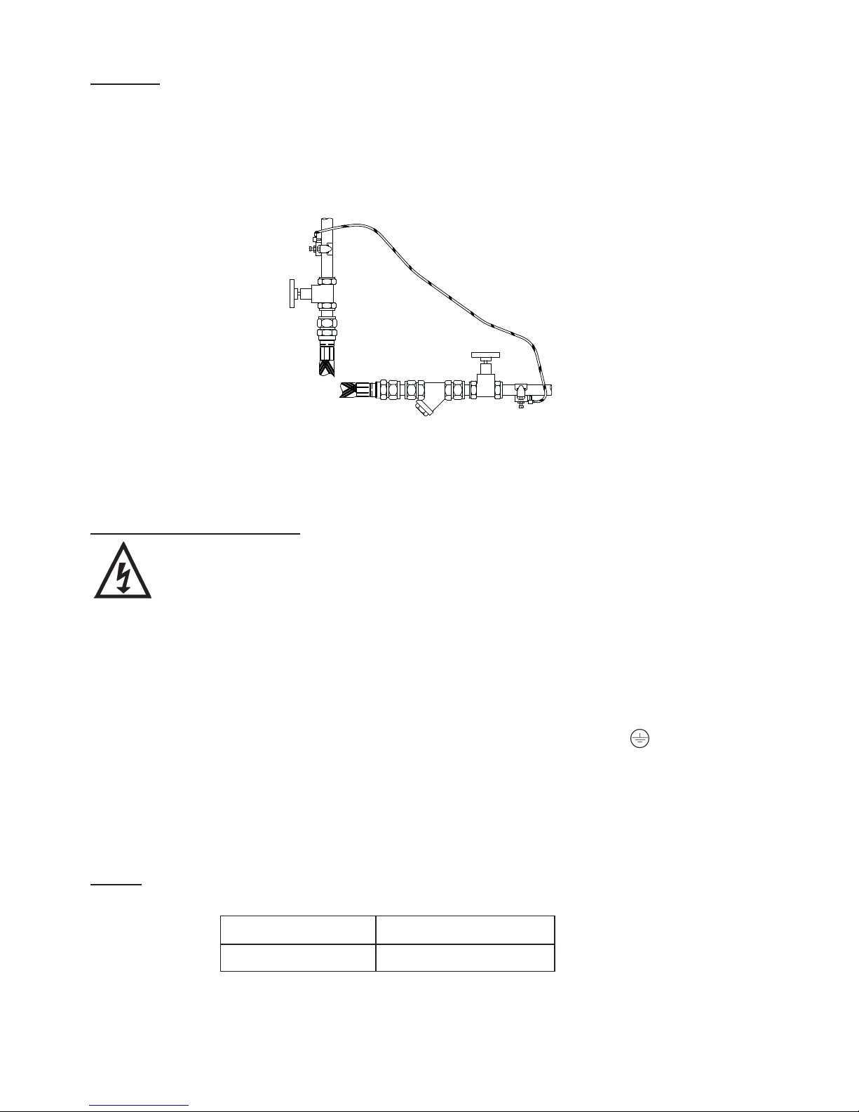
Siting of the Pump/Pipework . . . . . . . . . . . . 4
Electrical Installation . . . . . . . . . . . . . . . . . . 6
INDEX . . . . . . . . . . . . . . . . . Page No
Noise . . . . . . . . . . . . . . . . . . . . . . . . . . . . . . 10
Commissioning . . . . . . . . . . . . . . . . . . . . . . 10
Maintenance . . . . . . . . . . . . . . . . . . . . . . . . 12
Trouble Shooting Guide. . . . . . . . . . . . . . . . 13
Environment Protection. . . . . . . . . . . . . . . . 13
IMPORTANT NOTES
Please read these instructions fully before
starting the installation:
The installation must comply with the relevant
water supply, electrical and building regulations
and be installed by a competent person.
If in doubt, consult Stuart Turner Ltd.
This appliance can be used by children aged from 8 years
and above and persons with reduced physical, sensory
or mental capabilities or lack of experience and knowledge if
they have been given supervision or instruction concerning
use of the appliance in a safe way and understand the
hazards involved. Children shall not play with the appliance.
Cleaning and user maintenance shall not be made by
children without supervision.
Children should be supervised to ensure that they do not
play with the appliance.
APPLICATION
The range of stainless steel peripheral pumps is designed to pump clean fresh water.
Other clean, non aggressive, non explosive liquids with similar characteristics to water may
be pumped. Consult Stuart Turner for such applications.
The pumps can be used for pressure boosting, fluid transfer and distribution. They are
suitable for flooded suction applications. Alternatively a maximum suction lift of 4.6 m is
permitted when using a Stuart footvalve/strainer.
WARNING AGAINST MISUSE
This pump set must not be used for any other application without the
written consent of Stuart Turner Limited. In particular, it must not be
connected directly to the mains water supply, or used outside the
conditions specified in the limits of application.

- 3 -
Cont ...
PRODUCT DESCRIPTION
Motor:
Induction type, totally enclosed fan ventilated cooling*, continuously rated*, class ‘F’
insulation. Motors comply with IEC34-1. Single phase versions incorporate a permanent
capacitor and integral auto resetting thermal overload protection.
The standard range of motors are suitable for a supply of 230V, 1 phase, 50Hz.
Optional motors are available on certain models to suit various voltages and frequencies
(see technical specification for details).
*Variations of rating and enclosure details can be found in the technical specification
section.
Pump
All models are close coupled to motor.
PH 45 TS S are of single stage, peripheral design, with vertical suction and discharge
ports.
Standard pump materials of construction of major wetted parts are as follows: -
Other seal material options are available on certain models.
Model Part No. Body Impeller Shaft Mechanical Seal
PH 45 TS S 46628 Stainless Steel Stainless Steel Stainless Steel Nitrile/Carbon
Sil Carbide/Stainless Steel
PH 45 TS S 46629 Stainless Steel Stainless Steel Stainless Steel Viton/Carbon
Sil Carbide/Stainless Steel
PH 45 TS S 46632 Stainless Steel Stainless Steel Stainless Steel Nitrile/Carbon
Sil Carbide/Stainless Steel

- 4 -
Cont ...
* With footvalve fitted.
**Note: Max working pressure is the maximum pressure that can be applied to the
pump internal casing under any installation conditions.
TECHNICAL SPECIFICATION
Stuart Turner reserve the right to amend the specification in line with its policy of
continuous development of its products.
Note: For information on other voltages/frequencies which are not shown, consult any
supplementary instruction sheet supplied, or the rating label attached to the
pump.
SITING OF THE PUMP/PIPEWORK
WARNINGS:
Pump Location
If possible site the pump in a location where in the unlikely event of a
liquid leak, any spillage is contained or routed to avoid electrics or
areas sensitive to liquid damage.
Care should be taken to protect the pump from frost and freezing.
Ensure pipework to and from pump is independently supported to
prevent stress on the pump inlet and outlet branches.
Do not fit a non-return valve, or devices which contain non-return
valves, in the suction (inlet) pipework to the pump. Exceptions can be
made in the case of suction lift installations when a footvalve is
required.
When a footvalve is required on installations that incorporate
automatic pump control, it is recommended that a suitable pressure
relief valve be fitted in the discharge (outlet) pipework from the pump.
Do not run against a closed valve for periods longer than 5 minutes.
LIMITS OF APPLICATION
Part
No Model Supply
Max.
Liquid
Temp.
oC
Min.
Liquid
Temp.
oC
Max.
Ambient
Air Temp
oC
Max.
Suction
Lift (m)
Max. Head
(Pump Closed
Valve) (m)
Max. Viscosity **Max.
Working
Pressure
kPa (bar)
Max. Inlet
Head (m) Max. No.
Starts/h
50 Hz 60 Hz (Redwood
No. 1 Scale) Centistokes 50 Hz 60 Hz
46628 PH 45 TS S 230/1/50 80 4 40 4.6* 40 - 50 9.5 600 (6) 21 - 60
46629 PH 45 TS S 230/1/50 80 4 40 4.6* 40 - 50 9.5 600 (6) 21 - 60
46632 PH 45 TS S 230/1/50/60 80 4 40 4.6* 30 37 50 9.5 600 (6) 21 21 60
Part
No Model Supply
Nominal
Watts
Output
(Motor)
Max. Watts
consumed
Full Load
(AMPS) Enc.
Rating Duty Rating
Dims (mm) Gross
Weight
(packed)
kg
Connections
50 Hz 60 Hz 50 Hz 60 Hz L W H Suction Delivery
46628 PH 45 TS S 230/1/50 370 518 - 2.4 - IPX4 Continuous
(S1) @ 2.5
l/min & above 249 130 166 6.5 G¾ M G¾ M
46629 PH 45 TS S 230/1/50 370 518 - 2.4 - IPX4 Continuous
(S1) @ 2.5
l/min & above 249 130 166 6.5 G¾ M G¾ M
46632 PH 45 TS S 230/1/50/60 370 410 570 2.0 2.5 IPX4 Continuous
(S1) @ 2.5
l/min & above 249 130 166 6.5 G¾ M G¾ M

- 5 -
Cont ...
Do not allow plastic pump parts to come into contact with oil or
cellulose based paints, paint thinners or strippers, acid based
descalents or aggressive cleaning agents.
Do not introduce solder flux to pumps or pump parts manufactured
from plastic. All solder joints should be completed and flux residues
removed prior to pump connection.
Always install isolating valves to both suction and delivery pipework.
The motor casing can become very hot under normal operating
conditions. Care should be taken to ensure it cannot be touched
during operation.
Site the pump in a dry, frost-free horizontal position where it cannot be sprayed with
water and as close to the liquid source as possible.
The pump enclosure must be ventilated and there should be a minimum clearance of
80 mm between the pump and housing on all sides.
To prevent loss of pressure through pipework, use pipe size to match pump whenever
possible, minimising 90° bends.
It must be ensured that storage capacity of the liquid supply is adequate for the flow
rates required by the pump.
The pipework feeds to the storage tank should be of adequate size to ensure
replenishment rate of tank is sufficient to meet the needs of the pump.
Isolating valves should be fitted in suction and delivery pipework to enable easy isolation
and access to the pump.
When the pump is to be installed in areas where there is a risk of debris or scale build up
within the system, it is recommended that the inlet pipework is fitted with an inline strainer.
Pump Mounted Above Liquid Source (Suction Lift)
The pumps can be used in a suction lift installation providing the height of lift is within the
limits specified in the limits of application section.
A footvalve and strainer must always be used and the suction pipework size should be
22 mm throughout.
Lay the suction piping over the shortest possible distance and ensure there is a constant
rise from the liquid source to the pump. Any high spots will cause air pockets to form,
reducing system efficiency.
Ensure all joints in suction pipework are completely airtight. Failure to comply will result
in loss of prime.
The intake of the footvalve/strainer should be positioned such that is cannot be blocked
with debris or silt that are frequently found in the bottom of sumps and wells.

- 6 -
Cont ...
When a footvalve is installed on installations that incorporate automatic pump control,
it is recommended that a suitable pressure relief valve be fitted in the discharge (outlet)
pipework from the pump.
ELECTRICAL INSTALLATION
WARNINGS:
The electrical installation must be carried out in accordance with the
current national electrical regulations by a competent person.
Before starting work on the electrical installation ensure the power
supply is isolated.
Where any of the pumps are installed in an area where there is a risk
of water spillage it is recommended that a residual current circuit
breaker having a rated current not exceeding 30 mA, be installed in
the supply circuit. This may be part of a consumer unit or a separate
unit.
This appliance must be earthed.
The motor and wiring must not be exposed to water.
Do not allow the supply cord to contact hot surfaces, including the
motor shell, pump body or pipework. The cord should be safely
routed and secured by cable clips.
The standard single phase pumps are suitable for a supply of 230V, 1 Phase, 50Hz.
Other voltages and frequencies are available on certain models and it is therefore very
important to ensure the voltage and frequency on the pump rating plate matches the
supply.
When installing a 230V, 1 phase, pump in the United Kingdom, means for disconnection
must be incorporated in the fixed wiring according to the Wiring Rules. This can be done
by permanently connecting the pump to the mains supply via a double pole switched, fused
connection unit complying with BS 1363-4.
When installing a 110V, 1 phase pump it must be in accordance with the current electrical
regulations that apply to the installation.
All motors exceeding 370 watt output should be provided with control equipment
incorporating means for protection against overload.
The spur box (fused connection unit) or starter to which the pump is connected should
be mounted in an easily accessible position and labelled if confusion is possible to allow
easy isolation of the unit.
All pumps are continuously rated.
INLET OUTLET
Fig. 1 PH 45 TS S

- 7 -
Cont ...
Earthing
This appliance must be earthed via the supply cord, which must be correctly connected
to the earth point located in the terminal box.
Metallic pipework must have supplementary earth bonding where the continuity has
been broken by flexible hoses or plastic components. Adjacent suction and delivery pipes
should be fitted with earthing clamps to BS 951 and connected with earthing wire size
4 mm² (Fig. 2).
Certain installations may require additional earthing arrangements such as equipotential
bonding. Reference should be made to the relevant regulations concerning this subject to
ensure compliance.
Wiring of connection unit:
WARNING: This appliance must be earthed.
The wires in the mains lead are coloured in accordance with the following code:
Green and Yellow: Earth Blue: Neutral Brown: Live
As the colours of the wires in the mains lead of this appliance may not correspond
with the coloured markings identifying the terminals in your connection unit
proceed as follows:
The wire which is coloured green and yellow must be connected to the terminal in the
connection unit which is marked with the letter E or by the earth symbol: or coloured
green or green and yellow.
The wire which is coloured blue must be connected to the terminal which is marked with
the letter N or coloured black.
The wire which is coloured brown must be connected to the terminal which is marked
with the letter L or coloured red.
Fuses
The following fuse size should be used with the appropriate pump:
Model Fuse Size (AMPS)
All models 5
Fig. 2
Diagram of earth
continuity connection.

- 8 -
Cont ...
Supply Cord Replacement:
The supply cord and internal wiring within the terminal box are routed and
secured to ensure compliance with the electrical standard EN 60335-1. It
is essential that prior to any disturbance of this internal wiring, all cable
routing and securing details are carefully noted to ensure re-assembly to
the same factory pattern is always maintained.
If the supply cord is to be changed or is damaged, it must be replaced with a special
cord assembly available from Stuart Turner or one of their approved repairers.
On disassembly note the cord retention and routing system. Re-assemble to the same
pattern.
For information on cable connection consult the wiring diagram and cable gland fitting
instructions.
Supply Cord Extension:
The pumps are fitted with a supply cord to the following specification:-
All models HO5VV-F3 G 0.75 mm² - 6 Amp rated cable.
If the supply cord is to be extended, a cord of the same specification should be used.
Any connections or junction boxes used should be specifically suited for the application
and installed in accordance with the manufacturers instructions.

- 9 -
Cont ...
1
2
3
12
110
EN
L
80
70
8
8(Dims. in mm)
Fig. 3
Fig. 5
Fig. 4
Cable Gland & Supply Cord Fitting Instructions (Single phase range)
The cable gland assembly Fig. 5 (items 1 & 2) provides the necessary protection against
ingress of solid objects and moisture as well as providing cable retention.
Assembly instructions are as follows: -
1. Ensure selected cable sheath
diameter is within the permitted range
(6.5 to 9.5 mm).
2. Strip and prepare the cable sheath
and insulators as shown in Fig. 3.
3. Disassemble cable gland as shown in
Fig. 5 and insert cable into position
ensuring ‘O’-ring (item 1) is placed
over the cable before the clamping
insert (item 2) is tightened.
4. Consolidate the stranded conductor
ends by twisting and shape the earth conductor
as shown in Fig. 4 (item 3).
5. Remove earth terminal post clamping
components and assemble as shown in
Fig. 4 ensuring shaped conductor is
orientated as shown and all strands of
the conductor are clamped between
the washers.
6. Insert and secure live and neutral
conductors ensuring all conductor
strands are clamped.
7. Confirm cable routing is as shown in
Fig. 5 and assemble and secure
terminal box lid.

- 10 -
Cont ...
NOISE
The equivalent continuous A-weighted sound pressure level from the pumpset does not
exceed 70 dB(A) at a distance of one metre.
COMMISSIONING
WARNINGS:
The motor casing can become very hot under normal operating
conditions, care should be taken to ensure it cannot be touched
during operation.
Do not run pump without guards and terminal box lid correctly fitted.
The pump chamber must be full of liquid at all times. Seal damage
will result if the pump runs dry.
1. System Flushing
Some pumps incorporate plastic and rubber components that must not
come into contact with solder flux, acid-based descalents or aggressive
cleaning agents. The pipework system should be flushed out prior to the
pump being connected, to ensure any contaminants/chemical residues and
foreign bodies are removed from elsewhere in the system.
Wiring Diagrams
The internal wiring within the terminal box are routed and secured to
ensure compliance with the electrical standard EN 60335-1. It is essential
that any disturbance of this internal wiring is avoided and the factory
routing and securing of all internal wiring is always maintained.
MAIN
WINDING
THERMO
TRIP CAPACITOR
START
WINDING
BLUE
BROWN
BLACK
TERMINAL
BLOCK
N
L
BLUE
BROWN
GREEN /
YELLOW
E
230 VAC/1PH/50Hz
SUPPLY
NL
RED
Fig. 6

- 11 -
Cont ...
2. Liquid Supply
Always ensure that liquid storage capacity is adequate to meet the demand.
Ensure the pump chamber is full of liquid before starting the pump. Failure
to do this could result in seal damage. To ensure dry running does not
occur the pumps must be primed as described in the priming section. Do
not run pump dry.
3. Ensure electrical supply is compatible with the details that are stated on the pump
rating plate. (The wrong voltage or frequency can be dangerous and may damage
the pump.)
4. Priming
a) Top suction model (flooded suction)
The pump must be primed (filled with liquid) before starting. Turn on liquid
supply, prime and vent the pump by unscrewing the priming plug (Fig. 7)
slowly until all air escapes and liquid emerges. Ensure the ‘O’-ring seal is retained
in place. Re-tighten the plug.
b) All models (suction lift installation)
Prime the suction pipework and pump by filling with liquid via the pump discharge
connection, or by filling the suction pipework before attaching to the pump, then
fill the pump.
5. Starting
a) Switch on power to the pump which will now be operational.
b) Carefully check pump and pipework for leaks whilst pump running and stationary
before leaving the installation unattended.
INLET OUTLET
PRIMING PLUG PRIMING PLUG
Fig. 7

- 12 -
Cont ...
6. Variable Performance:
PH 45 TS S pumps are designed to allow the performance of the pump to be modified
by turning the mounting plate through approximately 30º.
To change the performance of the pump, use the following procedure:-
1) The pump is supplied set in the maximum performance position (Fig. 9).
2) Turn the pump off electrically, isolate liquid supply to the pump and vent system
pressure.
3) Slacken the four M6 screws that retain the Pump Body to the motor. Liquid may
leak from the joint in the body of the pump.
4) To reduce the performance turn the Mounting Plate anti clockwise until the cast tang
contacts the M6 screw (see Fig. 8).
5) To increase the performance turn the Mounting Plate clockwise until the cast tang
contacts the M6 screw (see Fig.9).
6) Ensuring the ‘O’-ring seal is not trapped between the faces, re-tighten the four M6
retaining screws. This must be done evenly to ensure the correct function of the
pump. Tighten to 2.6 Nm, do not over tighten.
7) Repeat priming procedure detailed in Section 4 before restarting the pump.
8) Check pump and pipework for leaks whilst pump is running and stationary before
leaving the installation unattended.
For Further Technical Support
Note: When pumps are installed in another manufacturers original equipment, please
contact the manufacturer for advice.
Phone the Stuart Turner PumpAssist team on 0844 98 000 97. Our staff are trained to
help and advise you over the phone.
FLOW (l/min)
HEAD (metres)
Max. Performance
Min. Performance
Fig. 10
Increase Performance
Fig. 9
Reduce Performance
Fig. 8 M6 screw x 4
Cast tang
Pump Body
Mounting Plate

- 13 -
Cont ...
MAINTENANCE
WARNINGS:
Care should be taken to protect the pump from frost and
freezing.
Pump Location
If possible site the pump in a location where in the unlikely
event of a liquid leak, any spillage is contained or routed to
avoid electrics or areas sensitive to water damage.
1. No routine maintenance is required but provision should be made for easy access to
the pump to allow for repairs due to normal wear and tear.
2. Disconnect electrical supply before working on pump.
3. Turn off liquid supplies to the pump and release pressure by opening outlets before
attempting maintenance.
4. If the installation is fitted with a footvalve and strainer or inline suction strainer, the
strainer must be cleaned as necessary to ensure the pump has unrestricted flow.
5. After maintenance is completed, refer to commissioning section for instructions on
restarting pump.
Cleaners, Disinfectants and Descalents
On installations where chemical disinfectants or descalents are periodically
used, the compatibility of the chemical solution regarding the pump must be
considered.
Acid based descalents and aggressive cleaning agents must not come into
contact with the pump. The pump must be removed from the system prior to the
use of these products. The system should be flushed to remove all chemicals
before the pump is re-connected.
If in any doubt as to the suitability of the chemical solutions refer to Stuart
Turner Ltd.
STORAGE
If this product is not installed immediately on receipt, store in a dry, frost and vibration
free location in its original packaging.

- 14 -
Cont ...
TROUBLE SHOOTING GUIDE
ENVIRONMENT PROTECTION
Your appliance contains valuable materials which can be recovered or recycled.
At the end of the products’ useful life, please leave it at an appropriate local civic waste
collection point.
Symptoms Probable Cause Recommended Action
Pump will not start. Electrical supply. Check power to motor.
Check the circuit breaker is set.
Check the correct fuse is being used.
Starter thermal
overload tripped. Check overload in starter (if applicable).
Investigate cause of problem.
Internal motor
thermotrip activated. Wait for thermotrip to cool and auto-
reset. Investigate cause of problem.
Pump runs, but no
liquid. Air locked. Bleed pipework and pump to clear air.
No liquid supply. Check the supply valves are turned on.
Check outlet not restricted or blocked.
Connections
reversed. Check liquid connections are on the right
way round.
No flooded suction. Check the pump has a flooded suction
and is primed.
If a suction lift exists fit a Stuart footvalve/
strainer and ensure suction is airtight.
Prime the pump and suction pipe (see
commissioning section).

- 15 -
Cont ...
YOUR 1 YEAR GUARANTEE
Stuart Pumps are guaranteed by Stuart Turner Limited to be free from defects in
materials or workmanship for the applicable guarantee period from the date of purchase.
The applicable guarantee period is stated in the installation booklet supplied with the
pump. Within the guarantee period we will repair, free of charge, any defects in the pump
resulting from faults in material or workmanship, repairing, exchanging parts or exchanging
the whole unit as we may reasonably decide.
Not covered by this guarantee: Damage arising from incorrect installation, improper use,
unauthorised repair, normal wear and tear and defects which have a negligible effect on
the value or operation of the pump.
Reasonable evidence must be supplied that the pump has been purchased within the
applicable guarantee period prior to the date of claim (such as proof of purchase or the
pump serial number).
This guarantee is in addition to your statutory rights as a consumer. If you are in any
doubt as to these rights, please contact your local Trading Standards Department or
Citizen’s Advice Bureau.
In the event of a claim please telephone Stuart Turner Limited on 0844 980 0097 or
return your pump and flexible hoses with accessories removed, plugs, pipes etc. If you
have any doubt about removing a pump, please consult a professional.
Proof of purchase should accompany the returned pump to avoid delay in investigation
and dealing with your claim.

Stuart Turner Ltd, Henley-on-Thames, Oxfordshire RG9 2AD ENGLAND
Tel: +44 (0) 1491 572655, Fax: +44 (0) 1491 573704
[email protected].uk www.stuart-turner.co.uk
V.A.T. REG. No. 199 0987 92. Registered in England No. 88368. Registered Office: Market Place, Henley-on-Thames
DECLARATION OF CONFORMITY
2006/42/EC
BS EN ISO 12100-1, BS EN ISO 12100-2, BS EN 809
2006/95/EC
BS EN 60335-1, BS EN 60335-2-41
2004/108/EC
BS EN 55014-1, BS EN 55014-2, BS EN 55022, BS EN 61000-3-2, BS EN 61000-3-3,
BS EN 61000-4-2, BS EN 61000-4-3, BS EN 61000-4-4, BS EN 61000-4-5, BS EN 61000-4-6,
BS EN 61000-4-11
1999/519/EC
BS EN 62233
2011/65/EU
IT IS HEREBY CERTIFIED THAT THE STUART ELECTRIC MOTOR DRIVEN PUMPAS
SERIAL NUMBER BELOW, COMPLIES WITH THE ESSENTIAL REQUIREMENTS OF THE
ABOVE E.E.C. DIRECTIVES.
RESPONSIBLE PERSON
AND MANUFACTURER STUART TURNER LIMITED
HENLEY-ON-THAMES, OXFORDSHIRE
RG9 2AD ENGLAND.
Signed. . . . . . . . . . . . . . . . . . . . . . . . . . . . . . . . . . . . . . . . . Business Development Director
Stuart Turner are an approved company to BS EN ISO 9001:2000
Issue No. 2514/1-03 Pt. No. 19945
Other manuals for PH 45 TS S
1
Table of contents
Other Stuart Turner Engine manuals
Popular Engine manuals by other brands

ZIEHL-ABEGG
ZIEHL-ABEGG ZA top SM250.60B Original operating instructions

Nice
Nice Era Star A Series Instructions and warnings for installation and use

Leon Cycle
Leon Cycle MKL6BTFM Series installation instructions

SIMONINI Racing
SIMONINI Racing MINI 3 manual

Yamaha
Yamaha MZ175 owner's manual

Briggs & Stratton
Briggs & Stratton 310000 VERTICAL SERIES Operator's manual

Sumitomo Drive Technologies
Sumitomo Drive Technologies RHYTAX Maintenance manual

Wren Turbines
Wren Turbines 44i Kerostart owner's manual

Allmatic
Allmatic XTILUS Series manual

Enduro
Enduro ELITE SM1000-2 User instructions

SOMFY
SOMFY HOME MOTION Roll Up 28 WT instructions

WilTec
WilTec 92400 Operation manual