Stubbe CFP Series Installation instructions
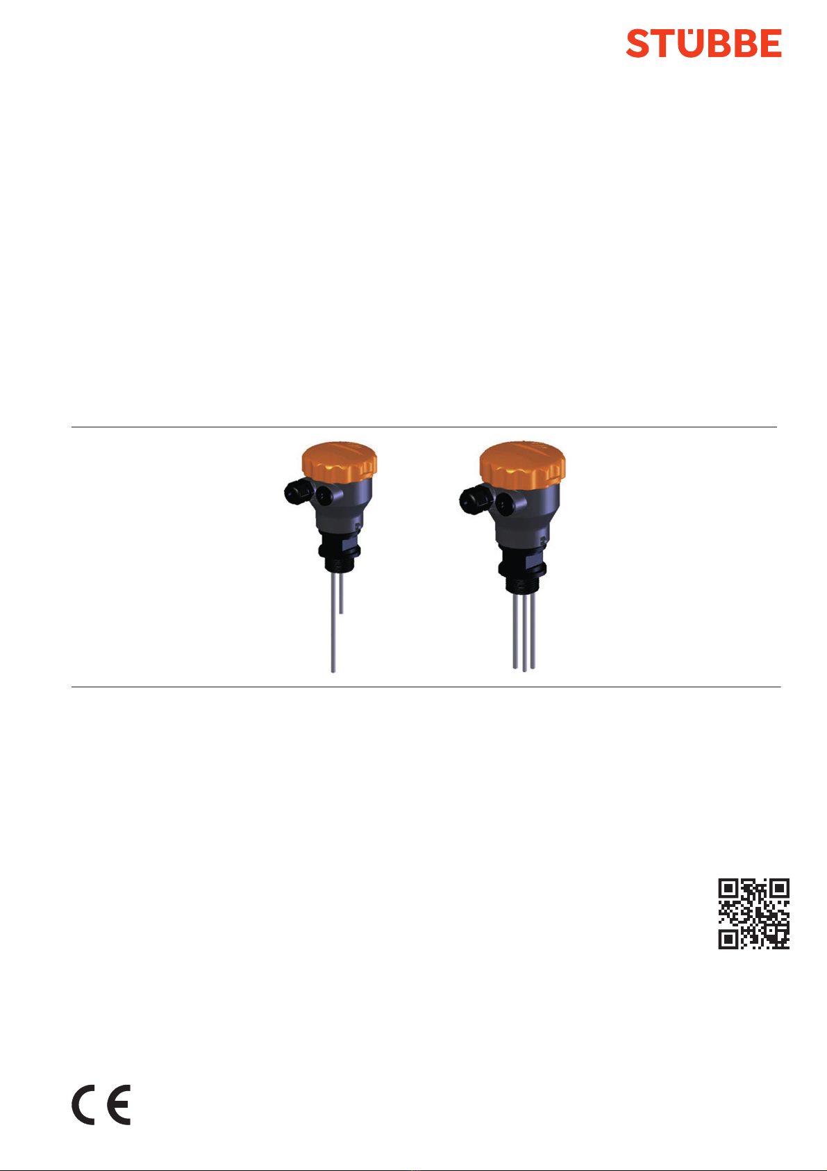
Conductive
limit level sensor
Original operating manual CFP series
Version BA-2022.08.31 EN
Print-No. 302 483
TR MA DE Rev001
STÜBBE GmbH & Co. KG
Hollwieser Straße 5
32602 Vlotho
Germany
Phone: +49 (0) 5733-799-0
Fax: +49 (0) 5733-799-5000
E-mail: co[email protected]
Internet: www.stuebbe.com
Subject to technical modifications.
Read carefully before use.
Save for future use.

Table of contents
Table of contents
1 About this document ............................... 3
1.1 Target groups ................................. 3
1.2 Other applicable documents ................ 3
1.3 Warnings and symbols ....................... 3
2 General safety instructions ....................... 4
2.1 Intended use .................................. 4
2.2 General safety instructions .................. 4
2.2.1 Obligations of the operating company ...... 4
2.2.2 Obligations of personnel ..................... 4
2.3 Hazardous media ............................ 4
3 Layout and Function ............................... 4
3.1 Marking ....................................... 4
3.2 Description .................................... 5
3.3 Layout ......................................... 5
4 Transport, Storage and Disposal ................. 5
4.1 Unpacking and inspection on delivery .. .. .. 5
4.2 Transportation ................................ 5
4.3 Storage ....................................... 5
4.4 Disposal ....................................... 5
5 Installation and connection ....................... 6
5.1 Preparations for installation ................. 6
5.1.1 Check operating conditions ................. 6
5.1.2 Preparation of the device .................... 6
5.1.3 Preparation of the vessel .................... 6
5.2 Install device .................................. 6
5.3 Electrical connection ......................... 6
6Operation ............................................ 6
6.1 Configure device ............................. 6
6.2 Commissioning ............................... 6
7 Maintenance ......................................... 7
7.1 Servicing ...................................... 7
7.2 Maintenance .................................. 7
7.2.1 Removing the device ........................ 7
7.2.2 Replacement parts and return .............. 7
8Faults................................................. 7
9 Appendix ............................................. 8
9.1 Technical data, operating limits, dimensions
and weights ................................... 8
9.2 Connection diagrams ........................ 8
9.2.1 Description of the contact points ............ 8
9.2.2 Connection diagrams ........................ 8
9.3 Output signals ................................ 9
9.3.1 Filling level indicator ......................... 9
9.3.2 2-state control unit ........................... 9
List of figures
Fig. 1 Name plate (example) ....................... 4
Fig. 2 Layout (example) ............................. 5
Fig. 3 Contact points for 2-rod probe
(example) ..................................... 8
Fig. 4 Contact points for 3-rod probe
(example) ..................................... 8
Fig. 5 Connection diagram, filling level
indicator ....................................... 8
Fig. 6 Connection diagram, 2-state control
unit ............................................ 9
List of tables
Tab. 1 Other application documents, purpose and
where found .................................. 3
Tab. 2 Warnings and symbols ....................... 3
Tab. 3 Servicing activities ........................... 7
Tab. 4 Troubleshooting .............................. 7
Tab. 5 Connection diagram, filling level
indicator ....................................... 8
Tab. 6 Connection diagram, 2-state control
unit ............................................ 9
2 CFP BA-2022.08.31 EN 302 483

About this document
1 About this document
This manual:
• is part of the equipment
• applies to all series referred to
• describes safe and proper operation during all operating
phases
1.1 Target groups
Operating company
• Responsibilities:
– Always keep this manual accessible where the device
is used on the system.
– Ensure that employees read and observe this docu-
ment, particularly the safety instructions and warnings,
and the documents which also apply.
– Observe any additional country-specific rules and reg-
ulations that relate to the system.
Qualified personnel, fitter
• Mechanics qualification:
– Qualified employees with additional training for fitting
the respective pipework
• Electrical qualification:
– Qualified electrician
• Transport qualification:
– Qualified transport specialist
• Responsibility:
– Read, observe and follow this manual and the other
applicable documents, especially all safety instructions
and warnings.
1.2 Other applicable documents
To download:
Resistance lists
Resistance of materials used to
chemicals
www.stuebbe.com/pdf/300051.pdf
To download:
CFP data sheet
Technical data and conditions of operation
www.stuebbe.com/pdf/302489.pdf
To download:
CE declaration of conformity
Conformity with standards
www.stuebbe.com/pdf/300771.pdf
Tab. 1 Other application documents, purpose
and where found
1.3 Warnings and symbols
Symbol Meaning
• Immediate acute risk
• Death, serious bodily harm
• Potentially acute risk
• Death, serious bodily harm
• Potentially hazardous situation
• Minor injury
• Potentially hazardous situation
• Material damage
Safety warning sign
Take note of all information
highlighted by the safety warning
sign and follow the instructions to
avoid injury or death.
Instruction
1., 2., ... Multiple-step instructions
Precondition
→Cross reference
Information, notes
Tab. 2 Warnings and symbols
302 483 BA-2022.08.31 EN CFP 3
Layout and Function
2 General safety instructions
The manufacturer accepts no liability for damages caused
by disregarding any of the documentation.
2.1 Intended use
The device is intended to be used for sensing the limit level of
electrically conductive liquid media, by contact.
• Only use the device with suitable media (→ resistance
lists).
• Adhere to the operating limits (→ Data sheet).
Avoidance of obvious misuse (examples)
• Do not use the device on media with the following charac-
teristics:
– Containing oil or grease
– Tendency to form non-conductive deposits
– Conductivity of the medium less than 16µS/cm
– Media to which stainless steel (1.4571) is not resistant
• Do not use the device in potentially explosive atmospheres.
2.2 General safety instructions
Observe the following regulations before carrying out any
work.
2.2.1 Obligations of the operating company
Safety-conscious operation
• Only operate the device if it is in perfect technical condition
and only use it as intended, staying aware of safety and
risks, and in adherence to the instructions in this manual.
• Ensure that the following safety aspects are observed and
monitored:
– Intended use
– Statutory or other safety and accident-prevention reg-
ulations
– Safety regulations governing the handling of haz-
ardous substances
– Applicable standards and guidelines in the country
where the pump is operated
• Make personal protective equipment available.
Qualified personnel
• Make sure all personnel tasked with work on the device
have read and understood this manual and all other appli-
cable documents, especially the safety, maintenance and
repair information, before they start any work.
• Organize responsibilities, areas of competence and the
supervision of personnel.
• The following work should be carried out by specialist tech-
nicians only:
– Installation, repair and maintenance work
– Work on the electrical system
• Make sure that trainee personnel only work on the device
under supervision of specialist technicians.
2.2.2 Obligations of personnel
Only complete work on the device if the following requirements
are met:
• System is empty
• System has been flushed
• System is depressurized
• System has cooled down
• System is secured against being switched back on again
• Do not make any modifications to the device.
2.3 Hazardous media
• When handling hazardous media, observe the safety reg-
ulations for the handling of hazardous substances.
• Use personal protective equipment when carrying out any
work on the device.
• Collect leaking pumped liquid and residues in a safe man-
ner and dispose of in accordance with environmental reg-
ulations.
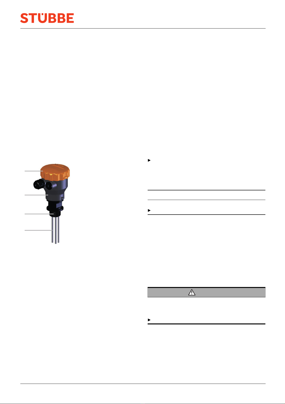
3 Layout and Function
3.1 Marking
CFP
Messbereich 1000 mm
18-30V DC Id.No.
141939
Anschluss DN25
Material PE
1
2
3
47
2 Relais 30V DC
5
6
Fig. 1 Name plate (example)
1Devicetype
2 Measurement range
3 Supply voltage range
4Outlet
5 Connection (nominal width)
6 Media connection and gasket material
7IDnumber
4 CFP BA-2022.08.31 EN 302 483
Transport, Storage and Disposal
3.2 Description
Thedeviceisaprobetobeusedforsensingthelimitlevelof
electrically conductive liquid media, by contact.
• When the medium makes contact with the sensor rods, this
creates a conductive connection which is evaluated by the
electronics in the connector head.
• Sensitivity adjustment via the potentiometer
• Device installed in the vessel so that it is perpendicular to
the surface of the medium
• 2-rod probe for indicating the minimum or maximum filling
level
• 3-rod probe in the following variants depending on the cir-
cuit board installed:
– 2-state control unit
– Indicates the minimum and maximum filling level
3.3 Layout
1
2
3
4
Fig. 2 Layout (example)
1 Housing cover
2 Connector head
3 Process connection
4 Sensor rods
4 Transport, Storage and
Disposal
4.1 Unpacking and inspection on delivery
1. Unpack the device when received and inspect it for trans-
port damage and completeness.
2. Check that the information on the type plate agrees with
the order/design data.
3. Report any transport damage to the manufacturer immedi-
ately.
4. If fitted immediately: Dispose of packaging material
according to local regulations.
– If fitted at a later point: leave device in its original pack-
aging.
4.2 Transportation
Device should preferably be transported in the original
packaging.
4.3 Storage
NOTE
Material damage due to inappropriate storage!
Store the device properly.
1. Make sure the storage room meets the following condi-
tions:
–Dry
– Frost-free
– Vibration-free
– Not in direct sunlight
– Storage temperature +10 °C to +60 °C
2. Device should preferably be stored in the original packag-
ing.
4.4 Disposal
WARNING
Substances hazardous to health!
The device contains substances that are hazardous to health
and the environment if disposed of improperly.
Do not discard the old device in household waste.
1. When disposed of via the manufacturer’s return system:
– If applicable, delete any personal data.
– Keep the old device separate from household waste
and return it to the manufacturer.
2. In the case of self-disposal:
– Remove battery.
– Disassemble electronic parts and plastic parts.
– Dispose of parts according to local regulations.
302 483 BA-2022.08.31 EN CFP 5

Operation
5 Installation and connection
5.1 Preparations for installation
5.1.1 Check operating conditions
1. Ensure the required operating conditions are met:
– Resistance of body and seal material to the medium
(→ resistance lists).
– Media temperature (→ Data sheet)
– Operating pressure (→ Data sheet)
2. Consult with the manufacturer regarding any other use of
the device.
5.1.2 Preparation of the device
1. Ensure the device is protected against ingress of moisture.
2. Cut the probe rods to length if necessary. Check the appli-
cation examples for the relevant type (→ 9.2.1 Description
of the contact points, Page 8 ).
3. Check that the uninsulated ends of the rods are not touch-
ingeachother.
5.1.3 Preparation of the vessel
The device can be installed in closed and open containers.
Wheninstalledinanopenvessel,thedeviceshouldbe
mounted on a suitable bracket (such as the PE installation
kit).
1. When installed in an enclosed vessel, ensure the approved
installation thread diameter G 1" is provided.
2. Check that the vessel provides sufficient immersion depth.
3. Align the vessel correctly, ensuring the following points are
satisfied:
– The device must be mounted perpendicular to the sur-
face of the medium
– Sufficient space for installation, electrical connection
and maintenance
5.2 Install device
The device installation is complete.
WARNING
Risk of injury and poisoning due to medium spraying out!
Use personal protective equipment when carrying out any
work on the fitting.
NOTE
Incorrect installation can lead to material damage!
Do not grip the top part of the housing to screw in the
device.
Insert a screwdriver into the process connection in order
to screw in the device perpendicular to the surface of the
medium.
5.3 Electrical connection
Cable without shielding can be used to connect the device.
If electromagnetic interference is anticipated, or if the cable
lengths are greater than 30 m, shielded cable should be
used.
The unit must be installed properly.
Power supply switched off and secured against being
switched back on again.
1. Unscrew the housing cover.
2. Guide the connection cable through the cable glands and
connect:
– Connection cable (→ Data sheet)
– Description of the contact points and circuit diagrams
(→ 9.2 Connection diagrams, Page 8 ).
3. Tighten the cable glands securely.
4. Screw on the housing cover.
6Operation
6.1 Configure device
If the medium exhibits either low conductivity or high con-
ductivity, it will be necessary to adjust the sensitivity using
the potentiometer.
The potentiometer is described in the connection diagrams
(→ 9.2.2 Connection diagrams, Page 8 ).
The device is installed and connected.
1. Fill the vessel until the medium makes contact with the
probe rods.
2. Unscrew the housing cover.
3. Switch on power supply.
4. To increase the sensitivity, turn the potentiometer clock-
wise.
5. To decrease the sensitivity, turn the potentiometer anti-
clockwise.
The LEDs indicate that the respective limit level has been
reached.
6. Switch off power supply.
7. Screw on the housing cover.
6.2 Commissioning
The device is installed and connected.
The device has been adjusted.
Switch on power supply.
When the medium makes contact with the sensor rods, the
device will indicate the minimum or maximum filling level.
If the device is fitted with a 2-state control unit, the corre-
sponding circuit will be activated.
6 CFP BA-2022.08.31 EN 302 483
Faults
7 Maintenance
WARNING
Risk of injury and poisoning due to hazardous media and
improper operating procedure!
Use personal protective equipment when carrying out any
work on the device.
Disconnect the power supply and secure it against being
switched back on again.
Block the infeed of media to the vessel / the device.
Depressurize the vessel / thedeviceandallowittocool
down.
Safely collect the media and dispose of it in accordance
with environmental regulations.
7.1 Servicing
Interval Action
As
necessary
Clean device with a damp cloth.
If deposits
occur
Clean the probe rods. Ensure that the
materials are resistant to the cleaning
agents (→ resistance list).
Six-mont-
hly
Perform a visual and functional check:
• Normal operating conditions unchanged
•Noleaks
Tab. 3 Servicing activities
Perform maintenance tasks according to the table.
7.2 Maintenance
7.2.1 Removing the device
System is empty.
System has been flushed.
System is depressurized.
System has cooled down.
System must be secured against being switched back on
again.
1. Disconnect the supply cable.
2. Take the device out of the vessel.
3. Decontaminate device if required.
7.2.2 Replacement parts and return
1. Have the following information ready to hand when order-
ing spare parts (→ Type plate).
–Devicetype
– ID number
– Nominal pressure and diameter
– Body and seal material
2. Please complete and enclose the document of compliance
for returns
(→ www.stuebbe.com/en/service/download).
3. Use only spare parts from STÜBBE.
8Faults
WARNING
Risk of injury and poisoning due to hazardous media liq-
uids!
Use personal protective equipment when carrying out any
work on the device.
Fault Possible
cause
Corrective action
Deposits on the
probe rods
Clean the probe
rods. Ensure that the
materials are resistant
to the cleaning agents
(→ resistance list).
No supply
voltage
Check the supply voltage
and if necessary switch it
on.
Check the electrical con-
nection and if necessary
make the correct con-
nection (→ 5.3 Electrical
connection, Page 6 ).
Device
does not
trip
Sensitivity too
high / too low
Adjust the device correctly
(→ 6.1 Configure device,
Page 6 ).
Tab. 4 Troubleshooting
After the fault has been rectified, test the device.
Dip the probe rods into the medium and check the output
signals and input signals. If the device trips, the fault has
been rectified.
302 483 BA-2022.08.31 EN CFP 7
Appendix
9 Appendix
9.1 Technical data, operating limits,
dimensions and weights
The particulars are described on the data sheet (→ Data
sheet).
9.2 Connection diagrams
9.2.1 Description of the contact points
2-rod probe
21
Fig. 3 Contact points for 2-rod probe (example)
1 Reference (black probe)
2 Minimum/maximum (relay 4 / blue probe)
3-rod probe
2
1
3
Fig. 4 Contact points for 3-rod probe (example)
1 Reference (black probe)
2 Maximum (relay 4 / blue probe)
3 Minimum (relay 3 / red probe)
9.2.2 Connection diagrams
Filling level indicator
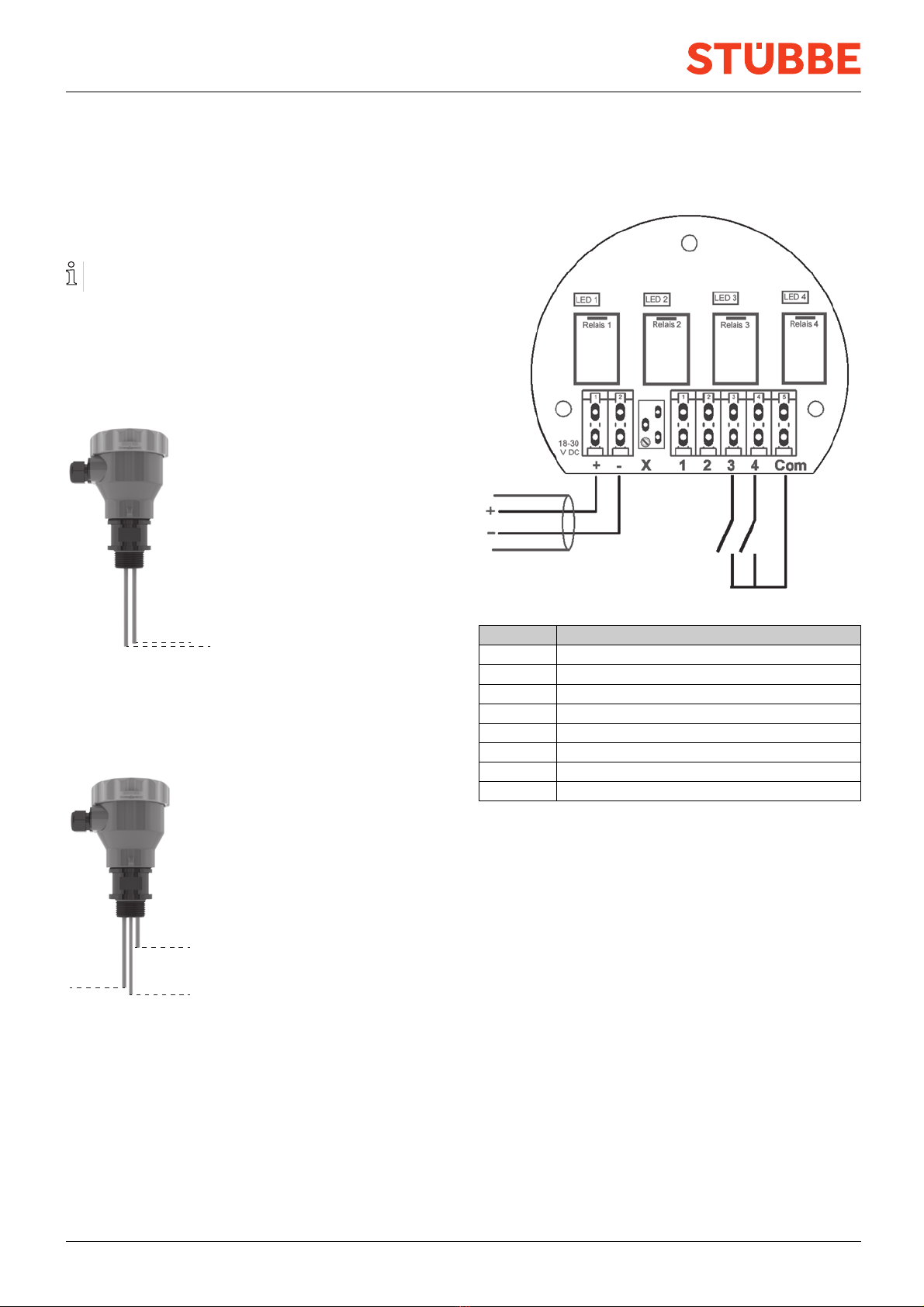
Fig. 5 Connection diagram, filling level indicator
Terminal Connection
+Voltage supply (18...30 V DC)
-Voltage supply (0 V)
XPotentiometer for adjusting the sensitivity
1–
2–
3Relay 3 (NO)
4Relay 4 (NO)
Com Relay 1...4 (COM)
Tab. 5 Connection diagram, filling level indicator
8 CFP BA-2022.08.31 EN 302 483
Appendix
2-state control unit
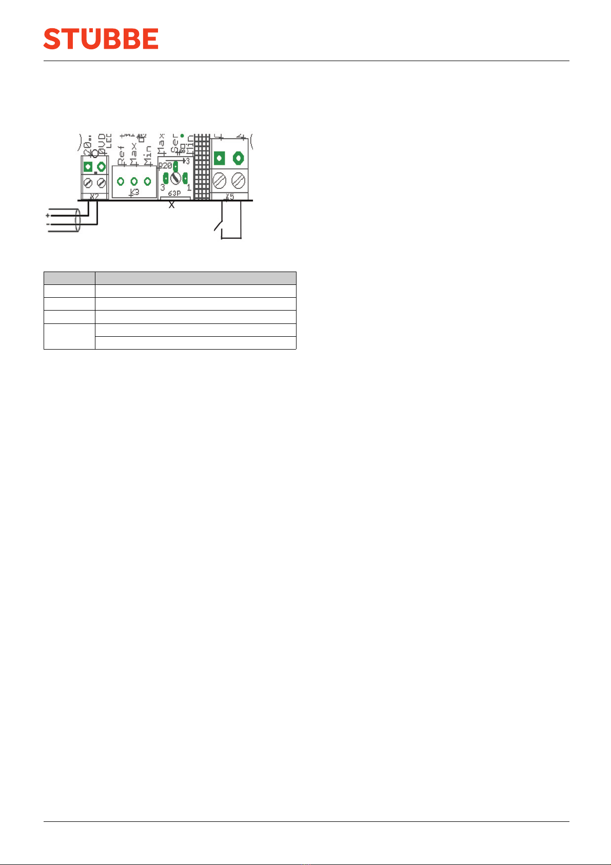
Fig. 6 Connection diagram, 2-state control unit
Terminal Connection
+Voltage supply (20...30 V DC)
-Voltage supply (0 V)
XPotentiometer for adjusting the sensitivity
Relay (NO)
X5
Relay (COM)
Tab. 6 Connection diagram, 2-state control unit
9.3 Output signals
9.3.1 Filling level indicator
• Normally-open relay (NO)
• 2A/30 V DC or 0.5 A/125 V AC
• Common Com connection
9.3.2 2-state control unit
• Normally-open relay (NO)
• 8A/250 V AC
302 483 BA-2022.08.31 EN CFP 9
Table of contents
Popular Accessories manuals by other brands


BOMANN
BOMANN KSG 238.1 instruction manual

TFA
TFA 30.3249.02 instruction manual

enika
enika P8 T TempRh IP quick start guide

Oregon Scientific
Oregon Scientific BAR609HGA user manual

Bosch
Bosch rexroth RegisterControl ATEX MLC 14VRS operating instructions

Agilent Technologies
Agilent Technologies 8495 Operating and service manual