Stucki HS-7-100 User manual
A. Stucki Company
2600 Neville Road, Pittsburgh, PA 15225
Phone 412.770.7300, Fax 412.771.7308
08072 www.stucki.com Revision 001, 6/12/2007
INSTALLATION INSTRUCTIONS FOR STUCKI®HS-7-100 HYDRAULIC
STABILIZERS
I. INTRODUCTION
The Stuck HS-7-100 stabilizer is a single-acting hydraulic damper that
fits into the freight car spring nest and operates as the truck springs
are compressed. One unit is installed in each spring group in the
space normally occupied by the center position truck spring when
applied with a typical D-5 spring group. This stabilizer is designed to
function only under a loaded car condition, no damping occurs when
the car is empty.
The Stucki HS-7-100 center position unit should not be confused with
the Stucki HS-7, which is designed to fit in an outboard spring position
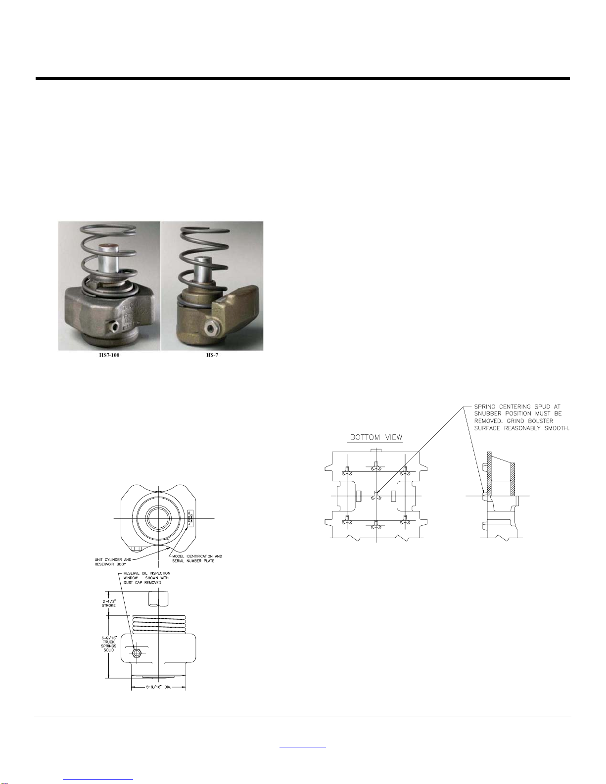
only. Figure 1 clearly illustrates the distinctive features of each unit.
Note particularly that the body springs are not interchangeable
between the two models.
Figure 1. Comparison of HS-7-100 (left) & HS-7 (right)
Standard HS-7-100's are designed for use on 100-ton freight cars.
They can be used with either D-5 or D-7 truck spring groups. Units
having damping characteristics suitable for 70-ton cars are designated
as HS-7-100-B's.
The model is identified on the unit serial number tag as shown in
Figure 2. Whenever a Stucki stabilizer is to be replaced, it is important
that it be replaced by a unit of equal capacity rating. Factory rebuilt
units will have the letters “RB” and the date they were rebuilt stamped
on the model identification tag.
Figure 2. HS-7-100 Identification
II. STORAGE PRECAUTIONS
Each HS-7-100 stabilizer is packaged in a manner that under normal
circumstances will prevent corrosion of the piston rod while in storage.
Units should not be stored outdoors any longer than necessary.
Incoming stock should be rotated, and units held in long-term storage
should be protected from moisture. Units which have been stored for
long periods should be inspected for any signs of rust on the chrome
surface of the piston rods before using.
III. SPRING GROUPS
For optimum performance the HS-7-100 must be applied with the
proper combination of truck springs. A. Stucki company's general
HS-7-100 truck arrangement drawings list recommended groups for
conventional applications. In special cases where cars are to be used
in assigned service for loads which will consistently be significantly
greater or less than their rated capacity, Stucki Company should be
contacted for a compatible spring group recommendation.
When stabilizers are applied on a retrofit basis to older cars the
existing truck springs if re-used, should be load or height checked
according to AAR Specifications.
IV.INSTALLATION OF THE HS-7-100 INTO TRUCK
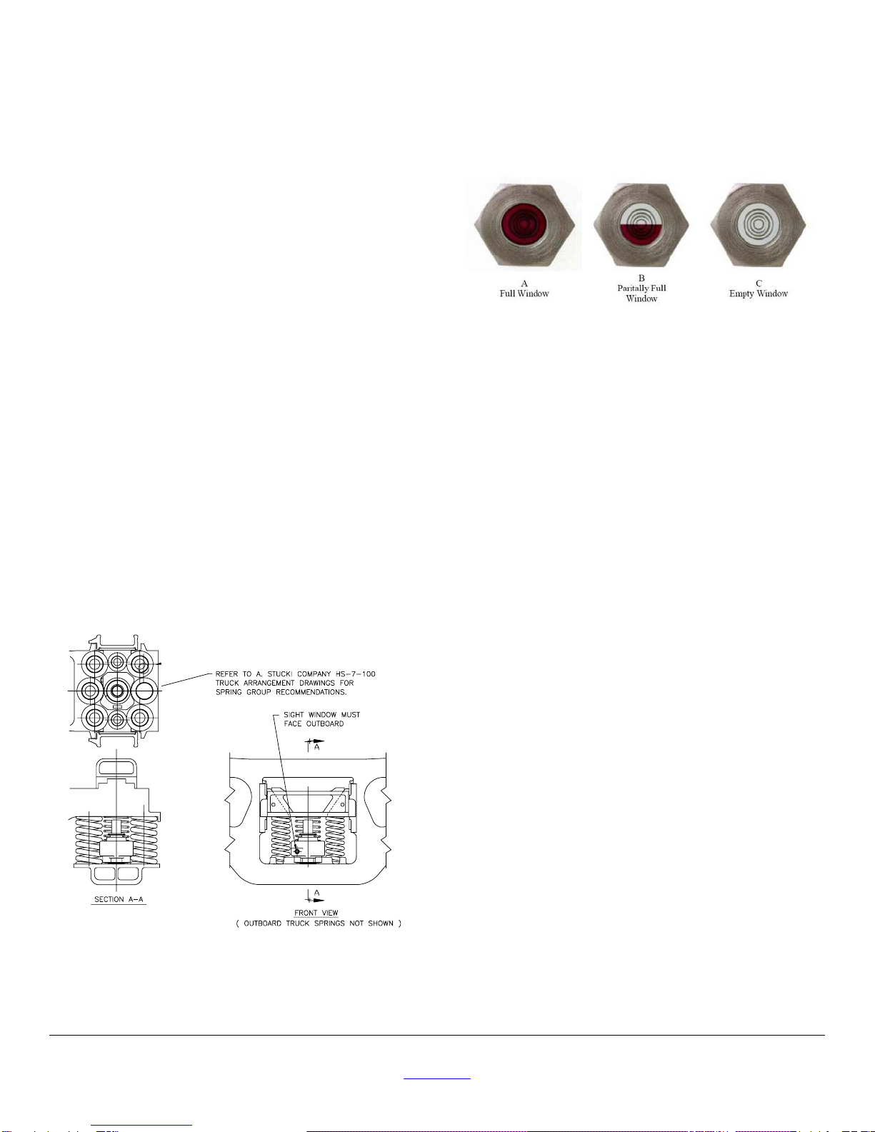
Figure 4 shows an HS-7-100 in a conventional combination type
7-position spring nest. Note how the stabilizer reservoir utilizes the
free space between the center spring position and the side coil
positions. With some rare exceptions (which should be approved by A.
Stucki Company), this is the only spring arrangement that permits the
use of the HS-7-100.
In most cases installation of the HS-7-100 requires no modification of
the truck bolster or side frame. However, some Barber or S-2 type
bolsters will have a spring centering boss at the center position which
must be removed as indicated in Figure 3.
Figure 3. Removal of Spring Centering Spud
Once the installer has checked that there are no projections on the
side frame or bolster that will interfere with the flush seating of the
stabilizer, the unit can be placed into position as follows:
1. Install all but outboard row of truck springs in their respective
positions (see "spring groups").
2. Remove HS-7-100 from shipping bag and remove cardboard
sleeve from the piston rod (in all cases where unit exchange is
being made, sleeve should be installed over piston rod of unit
being removed from car, to protect it during shipping).
3. Place body spring on unit as illustrated in Figure 1.
4. Position unit, piston rod up, in truck as illustrated in Figure 4.
Make certain sight window is facing outward (toward installer).
5. Install remaining truck springs
A. Stucki Company
2600 Neville Road, Pittsburgh, PA 15225
Phone 412.770.7300, Fax 412.771.7308
08072 www.stucki.com Revision 001, 6/12/2007
V. REMOVAL / REPLACEMENT OF HS-7-100
If it becomes necessary to remove and replace an HS-7-100 see
Section VI: Field Inspection of the HS-7-100. The unit can be easily
removed after removing the two outboard truck springs, and the
replacement unit installed in its place. Please note that units removed
due to a low reserve oil level condition can be returned to A. Stucki
Company to be rebuilt. It is advisable to mark on the returned unit the
car number and date removed if warranty credit is applicable. It is also
important that the cardboard sleeve taken from the piston rod of the
new unit be placed on the rod of the used unit to protect it from
damage during shipping.
If units are being removed and returned to A. Stucki Company as part
of a normal rebuild cycle, the body springs may be re-used but should
be checked for wear or damage.
*Note that the damping characteristics of the Stucki HS-7-100 are
identical to those of the HS-7 and its predecessor, the Stucki HS-6,
within a given capacity rating. Thus, on the basis of performance they
are interchangeable. However, the installer must insure that the
retention requirements specified in the installation instructions for the
particular design are fulfilled. Also, to alleviate future logistics
problems, it is advisable not to mix various models on a given car.
VI.FIELD INSPECTION OF THE HS-7-100
The HS-7-100 incorporates a low pressure seal on the piston rod
which characteristically will pass slight amounts of oil under normal
operating conditions. This oil will gradually accumulate on the body of
the unit and on the side frame spring seat, and will attract considerable
dirt. A dirty, oily appearance does not in itself constitute a defective
unit. Lost fluid is compensated for by reserve oil in the unit which
comprises about 45 percent of the total oil volume of 1350ml (46
ounces). The availability of reserve oil can be checked by visual
inspection of the oil level sight glass on the reservoir (see Figure 2).
The gage consists of a plug with a glass window, located such that the
presence of oil in the window is an indication of a functioning unit.
Figure 5 illustrates the conditions that can be encountered on visual
inspection of the sight glass. When the oil level is above the window,
the entire glass area will appear dark, as in illustration "A". Once the
oil level has dropped into the window area as in "B", the portion of two
rings on the inside of the glass above the oil level will reflect light back
to the viewer and appear shiny as shown. When the oil level recedes
below the window, these "shiny" rings will be totally visible as complete
circles as in "B".
Figure 4. Arrangement of HS-7-100
in Conventional Freight Car Truck
When inspecting the sight glass, the unit must be sitting in its normal
operating, upright position.
If the inspection of the oil level sight glass reveals condition "C" the unit
should be scheduled for replacement as soon as practical and returned
to A. Stucki Company to be rebuild. When the oil level is in the window
area, as in "B", the unit should be scheduled for replacement when the
car is next shopped. As long as the window shows full, as in "A", the
unit should be left in service, regardless of any external oil sludge
accumulation.
We strongly recommend units not be opened for refilling in the field.
This can lead to dirt contamination or overfilling with excess oil. Either
condition will result in damage to the seal and so will void the warranty.
Figure 5. Oil Level Sight Glass Conditions


