Studer RCC-02 User manual

Studer Innotec SA 2014 –V4.4.0
4O9C
Remote control and programming unit
RCC-02 and RCC-03 for the Xtender
User manual


Studer Innotec SA
RCC-02/-03
User manual V4.4.0 1
SUMMARY
1Foreword ................................................................................................................................................... 5
1.1 Conventions............................................................................................................................................. 5
1.2 Product recycling ................................................................................................................................... 5
1.3 EC Declaration of conformity............................................................................................................... 6
1.4 Studer Innotec contact details ............................................................................................................ 6
1.5 Your reseller’ contact details................................................................................................................ 6
2Warnings and caution ............................................................................................................................. 7
2.1 Warranty ................................................................................................................................................... 7
2.2 Limitation of responsability .................................................................................................................... 7
2.3 Safety instructions ................................................................................................................................... 7
2.4 Acceptance of the software licence and updates ........................................................................ 7
2.5 Compatibility ........................................................................................................................................... 8
2.6 Access code for extended functions ................................................................................................. 8
3Introduction............................................................................................................................................... 9
3.1 Models concerned ................................................................................................................................. 9
3.2 Controls and indicators.......................................................................................................................... 9
3.3 SD card ................................................................................................................................................... 10
4Connection ............................................................................................................................................. 11
4.1 Series connection ................................................................................................................................. 11
4.1.1 RCC-02 ............................................................................................................................................ 12
4.1.2 RCC-03 ............................................................................................................................................ 12
4.1.3 Xtender XTH .................................................................................................................................... 12
4.1.4 Xtender XTM ................................................................................................................................... 12
4.1.5 Xtender XTS ..................................................................................................................................... 13
4.1.6 VarioString....................................................................................................................................... 13
4.1.7 VarioTrack ....................................................................................................................................... 13
4.1.8 BSP .................................................................................................................................................... 13
4.1.9 Xcom-232i ....................................................................................................................................... 14
5Dimensions.............................................................................................................................................. 15
5.1 RCC-02 .................................................................................................................................................... 15
5.2 RCC-03 .................................................................................................................................................... 15
6Quick Start Guide................................................................................................................................... 16
6.1 Setting of the language ...................................................................................................................... 16
6.2 Adaptation to the source ................................................................................................................... 16
6.3 Adaptation to the battery .................................................................................................................. 17
6.4 Activation of the function Smart-Boost............................................................................................. 18
7Basic displays ......................................................................................................................................... 19
8Activating and deactivating the combi Xtender............................................................................... 20
9Quick setting of the maximum source AC current ............................................................................ 20
10 Setting of the RCC remote control.................................................................................................... 21
10.1 Setting of the language {5000} ...................................................................................................... 21
10.2 Other languages {5036}................................................................................................................... 21
10.3 Setting of time {5001} and date {5002} ......................................................................................... 22
10.4 User level {5012}................................................................................................................................. 22
10.5 Drive the remote control to the user level basic {5019} ............................................................ 22
10.6 INSTALLER - Modification of the Xtender parameters thresholds together {5042}................ 22
10.6.1 Force all Xtender parameters to threshold {5043} .................................................................. 22
10.6.2 Restore the default thresholds of the Xtender parameters {5044} ...................................... 22
10.7 Data logger {5057}............................................................................................................................ 23
10.7.1 Data logger enabled {5101} ....................................................................................................... 23
10.7.2 Backup of the current day data {5059} .................................................................................... 23
10.8 Backup and restoring {5013}........................................................................................................... 23
10.8.1 Backup of all files {5041} (System backup)............................................................................... 23
10.8.2 Restore all files {5068} (System recovery) .................................................................................. 23
10.8.3 Apply configuration files (master file) {5070}............................................................................ 24
10.8.4 Separator of the csv files {5032}.................................................................................................. 24

Studer Innotec SA
RCC-02/-03
2 V4.4.0 User manual
10.8.5 Advanced backup functions {5069} ......................................................................................... 24
10.9 Adjusting the contrast ...................................................................................................................... 25
10.10 Back-lighting {5007} .......................................................................................................................... 25
10.10.1 Backlight modes {5093} ............................................................................................................ 25
10.10.2 Duration of the back-lighting {5009}...................................................................................... 25
10.10.3 Red back-lighting if the Xtender is OFF and if there is a fault {5026}............................... 25
10.11 Extended and special functions {5021} ........................................................................................ 25
10.11.1 Choice of the display by default {5073} ............................................................................... 25
10.11.2 Inactivity period before returning to the standard display {5010} ................................... 25
10.11.3 Duration of display for quick messages {5011} .................................................................... 26
10.11.4 Acoustic alarm {5027}............................................................................................................... 26
10.11.5 Remote control acoustic alarm duration {5031} ................................................................. 26
10.11.6 Switching on and off of system on level View only {5056}................................................. 26
11 Information on the operating mode of the installation .................................................................. 27
11.1 Display of the parallel and three-phase systems........................................................................ 29
12 Messages and account of events .................................................................................................... 30
12.1 (000) Warning: Battery voltage low............................................................................................... 30
12.2 (003) AC-In synchronization in progress ........................................................................................ 30
12.3 (004) Input frequency AC-In wrong............................................................................................... 31
12.4 (006) Input voltage AC-In too high................................................................................................ 31
12.5 (007) Input voltage AC-In too low ................................................................................................. 31
12.6 (008) Halted: Inverter overload SC ................................................................................................ 31
12.7 (014) Halted: Over temperature EL ............................................................................................... 31
12.8 (015) Halted: Inverter overload BL ................................................................................................. 32
12.9 (016) Warning: Fan error detected................................................................................................ 32
12.10 (018) Warning: Excessive battery voltage ripple......................................................................... 32
12.11 (019) Halted: Battery under voltage.............................................................................................. 32
12.12 (020) Halted: Battery overvoltage ................................................................................................. 32
12.13 (021) Input limit reached, no transfer ............................................................................................ 32
12.14 (022) Error: Voltage presence on AC-Out.................................................................................... 33
12.15 (023) Error: Inverter phase not defined ......................................................................................... 33
12.16 (024) Check the clock battery ....................................................................................................... 33
12.17 (041) Warning: Overtemperature TR ............................................................................................. 33
12.18 (042) Halted: Unauthorized energy source at the output......................................................... 33
12.19 (058) Error: Synchronization with master lost ................................................................................ 33
12.20 (059) Halted: Inverter overload HW ............................................................................................... 33
12.21 (060) (061) Warning: Time security for auxiliary contacts .......................................................... 34
12.22 (062) Warning: Genset, no AC-In coming after AUX command ............................................. 34
12.23 Stored events ..................................................................................................................................... 34
13 Data logging ....................................................................................................................................... 35
13.1 Functioning......................................................................................................................................... 35
13.2 Analysis and visualization of the data with the XTENDER Data Analysis Tool ........................ 35
14 Setting of the Xtender ........................................................................................................................ 36
14.1 General ............................................................................................................................................... 36
14.2 Configuration on a system with several Xtenders ...................................................................... 36
14.3 Utilisation and access levels............................................................................................................ 36
14.4 Pre-defined functions of the auxiliary relays ................................................................................ 36
14.5 Access to the parameters............................................................................................................... 37
14.5.1 Access to a parameter by its number ...................................................................................... 37
14.5.2 Access to a parameter via the menu....................................................................................... 37
14.6 INSTALLER - Utilisation and access levels ...................................................................................... 38
14.7 Basic settings {1100}.......................................................................................................................... 38
14.7.1 Setting of the basic parameters by means of the potentiometer in the XTS {1551} ........ 38
14.7.2 Maximum current of the AC source (Input limit) {1107}......................................................... 39
14.7.3 Charge current {1138} .................................................................................................................. 39
14.7.4 Smart boost authorized {1126}.................................................................................................... 40
14.7.5 Authorized inverter {1124}............................................................................................................ 40
14.7.6 Type of detection of the grid loss (AC-In) {1552} .................................................................... 40

Studer Innotec SA
RCC-02/-03
User manual V4.4.0 3
14.7.7 Standby level {1187} ..................................................................................................................... 41
14.7.8 Restore default configurations {1395} ....................................................................................... 41
14.7.9 INSTALLER - Restore factory settings {1287}............................................................................... 41
14.8 Management and battery cycle {1137} ...................................................................................... 42
14.8.1 Authorized charger {1125}........................................................................................................... 45
14.8.2 Battery charge current {1138}..................................................................................................... 45
14.8.3 Temperature correction coefficient {1139}.............................................................................. 45
14.8.4 Undervoltage {1568} ..................................................................................................................... 45
14.8.5 Maximum operating voltage {1121}.......................................................................................... 47
14.8.6 Reactivation voltage after battery overvoltage {1122} ........................................................ 47
14.8.7 Battery maintenance voltage (floating) {1140} ...................................................................... 47
14.8.8 Force passage to floating mode {1467} ................................................................................... 47
14.8.9 New cycle {1141}........................................................................................................................... 47
14.8.10 Absorption phase {1451} .......................................................................................................... 48
14.8.11 Equalization phase {1452} ........................................................................................................ 49
14.8.12 Reduced floating phase {1453} .............................................................................................. 51
14.8.13 Periodic absorption phase {1454} .......................................................................................... 51
14.9 Inverter {1186} .................................................................................................................................... 52
14.9.1 Authorized inverter {1124}............................................................................................................ 52
14.9.2 Output voltage {1286}.................................................................................................................. 52
14.9.3 Increase of the linear AC-Out voltage with the battery voltage {1548} ............................ 53
14.9.4 Maximum increase of the AC-Out voltage by the battery voltage {1560} ....................... 53
14.9.5 Frequency {1112}........................................................................................................................... 53
14.9.6 Increase of the frequency at full battery {1536} ..................................................................... 53
14.9.7 Frequency increase with the battery voltage {1549}............................................................. 54
14.9.8 Maximum increase of the frequency {1546}............................................................................ 54
14.9.9 Speed of the change output voltage/frequency according to the battery voltage
{1534} ............................................................................................................................................... 55
14.9.10 Standby and start (load detection) {1420} .......................................................................... 55
14.9.11 Solsafe presence, energy source at AC-Out side {1438}................................................... 56
14.10 AC-In and transfer {1197}................................................................................................................. 56
14.10.1 Authorized transfer {1128} ........................................................................................................ 56
14.10.2 Delay before closing of the transfer relay {1580} ................................................................ 56
14.10.3 Smart-Boost authorized {1126} ................................................................................................ 56
14.10.4 Limitation of the Smart-boost power {1607} ......................................................................... 56
14.10.5 Maximum current of the AC source (Input limit) {1107} ..................................................... 57
14.10.6 Adaptation of the input current {1471} ................................................................................. 57
14.10.7 Authorization to exceeding the maximum current of the source (Input limit) without
interrupting the transfer {1436} ................................................................................................ 58
14.10.8 Type of detection of the grid loss (AC-In) {1552}................................................................. 58
14.10.9 Sensitiveness of the detection « tolerating » of grid loss (AC-In) {1510} .......................... 59
14.10.10 Transfer AC-In for delayed transfer opening {1199}............................................................ 59
14.10.11 Delay before passing to inverter {1198} ................................................................................ 59
14.10.12 Immediate transfer AC-In voltage {1200} ............................................................................. 59
14.10.13 INSTALLER –Absolute maximum input voltage {1432}........................................................ 59
14.10.14 Delta frequency allowed above the standard input frequency {1505} ........................ 59
14.10.15 Delta frequency allowed below the standard input frequency {1506} ......................... 59
14.10.16 Duration of erroneous frequency before disconnecting the transfer relay {1507} ...... 59
14.10.17 AC-In current active filtering {1575} ....................................................................................... 60
14.10.18 INSTALLER - Use an energy quota on AC-input {1557} ....................................................... 60
14.10.19 INSTALLER - AC-In Energy Quotas {1559} ............................................................................... 60
14.11 Configuration of auxiliary contacts 1 and 2 {1201} {1310} ........................................................ 60
14.11.1 Switching mode {1202} {1311}................................................................................................. 61
14.11.2 Combination of events mode {1497} {1498} ........................................................................ 61
14.11.3 Temporal restrictions {1203} {1312} ......................................................................................... 61
14.11.4 Contacts activated with set schedules {1269} {1378} ........................................................ 62
14.11.5 Contacts activated by an event {1455} {1456} ................................................................... 62
14.11.6 Contacts activated by the battery voltage {1245} {1353}................................................ 64

Studer Innotec SA
RCC-02/-03
4 V4.4.0 User manual
14.11.7 Contacts activated by inverter power or Smart-Boost {1257} {1366}.............................. 65
14.11.8 INSTALLER - Contacts activated according to the battery temperature {1503} {1504} ..
....................................................................................................................................................... 65
14.11.9 Contacts activated on battery state of charge (SOC) {1501} {1502} (function active
only with a BSP) .......................................................................................................................... 66
14.11.10 Security: Limit the time of activation {1512} {1513} ............................................................. 66
14.11.11 Maximum duration of activation {1514} {1515} ................................................................... 66
14.11.12 Reset all settings {1569} {1570}................................................................................................. 66
14.12 Auxiliary contacts 1 and 2 extended functions {1489} .............................................................. 67
14.12.1 Generator startup...................................................................................................................... 67
14.12.2 Generator control {1491} ......................................................................................................... 67
14.12.3 Number of starting attempts {1493}....................................................................................... 67
14.12.4 Starter pulse (with AUX2) {1492} .............................................................................................. 67
14.12.5 Time before a starter pulse {1494} .......................................................................................... 67
14.12.6 Main contact hold/interrupt time {1574} .............................................................................. 67
14.13 System {1101} ..................................................................................................................................... 68
14.13.1 Command entry {1537} ............................................................................................................ 68
14.13.2 Battery as priority energy source {1296}................................................................................ 69
14.13.3 Votage of the battery priority {1297} ..................................................................................... 69
14.13.4 Duration of the acoustic alarm {1565} .................................................................................. 69
14.13.5 Automatic restart {1129}........................................................................................................... 70
14.13.6 Ground/neutral system {1484}................................................................................................. 71
14.13.7 INSTALLER –Watchdog control system {1628} and {1629} ................................................. 71
14.13.8 INSTALLER –Flash saving of the parameter {1550} .............................................................. 71
14.13.9 Reset of all inverters {1468} ...................................................................................................... 71
14.14 Multi Xtender {1282}.......................................................................................................................... 71
14.14.1 3-phase integral mode {1283}................................................................................................. 72
14.14.2 Multiple authorized inverters {1461} ....................................................................................... 72
14.14.3 Multiple independent inverters {1462}................................................................................... 72
14.14.4 Battery cycle synchronized by the master {1555} ............................................................... 72
14.14.5 Authorize the stand-by of the secondary inverters (slaves) {1547}.................................. 72
14.14.6 Splitphase: L2 with 180 degrees phase displacement {1571} ........................................... 72
14.14.7 INSTALLER –Compatible Minigrid {1437} ............................................................................... 72
14.14.8 INSTALLER –Minigrid with battery energy sharing {1577} ................................................... 72
14.15 Grid-feeding {1522}........................................................................................................................... 73
14.15.1 Grid-feeding authorized {1127}............................................................................................... 73
14.15.2 Maximum grid-feeding current {1523}................................................................................... 73
14.15.3 Forced grid-feeding {1524} {1525} {1526}.............................................................................. 74
14.15.4 INSTALLER - Dephased injection {1610} ................................................................................. 74
14.15.5 INSTALLER - Cos phi at P=0% {1622} ........................................................................................ 75
14.15.6 INSTALLER - Cos phi at a given power. Cos phi {1623}, P= {1613} .................................... 75
14.15.7 INSTALLER - Cos phi at P=100% {1624}.................................................................................... 75
15 Information on the system ................................................................................................................. 76
15.1 Remote controls ................................................................................................................................ 76
15.2 Xtender................................................................................................................................................ 76
16 Software(s) updating.......................................................................................................................... 77
16.1 Updating process.............................................................................................................................. 77
17 Application examples ....................................................................................................................... 78
17.1 General use: Inverter, Charger with grid ...................................................................................... 78
17.2 Use of a limited power source ........................................................................................................ 78
17.3 Use to increase the power on an existing installation................................................................ 79
17.4 Load shedding of the second priority loads................................................................................ 79
18 Appendices......................................................................................................................................... 80
18.1 Appendix 1: List of configuration interdependencies ............................................................... 80
19 Parameter tables ................................................................................................................................ 81
19.1 Remote control parameters ........................................................................................................... 81
19.2 Inverter parameters .......................................................................................................................... 83
20 Parameter index {xxxx} ..................................................................................................................... 95

Studer Innotec SA
RCC-02/-03
User manual V4.4.0 5
1FOREWORD
This manual contains information relating to the functioning of the RCC-02 and RCC-03 remote
controls.
The use of certain functions sometimes requires advanced knowledge in various fields. This manual
cannot provide this. In case of doubt, please contact your reseller or installer.
1.1 CONVENTIONS
This symbol is used to indicate the presence of a dangerous voltage that is sufficient
to constitute a risk of electric shock.
This symbol is used to indicate a risk of material damage.
This symbol is used to indicate information that is important or which serves to optimize
your system.
Terminology:
The following terms are used in the manual to provide greater clarity:
RCC is used to indicate the remote control RCC-02 or RCC-03 if the description applies to both
models.
Installation is used to describe all the electrical equipment connected together. This may be the
source (public grid or generator), and one or more Xtender(s) with or without remote control as well
as electrical consumers.
System is used to describe the entirety of Xtenders with or without remote control.
Xtender or combi is used to describe one or more Xtender(s) connected together.
1.2 PRODUCT RECYCLING
The RCC remote control conforms to the European directive 2011/65/EU on hazardous substances
and does not contain the following elements: lead, cadmium, mercury, hexavalent chrome, PBB or
PBDE.
To dispose of this product, please use the service for the collection of electrical waste and observe
all applicable obligations according to the place of purchase.

Studer Innotec SA
RCC-02/-03
6 V4.4.0 User manual
1.3 EC DECLARATION OF CONFORMITY
The remote control, RCC-02/-03, described in this manual complies with the following standards:
EN 60950:2006, EN 61000-6-1:2007, EN 61000-6-3:2007
CH –1950 Sion, September 2014
Studer Innotec (R. Studer)
1.4 STUDER INNOTEC CONTACT DETAILS
Studer Innotec SA
Rue des Casernes 57
CH –1950 Sion
Tel. +41 (0)27 205 60 80
Fax. +41 (0)27 205 60 88
Customer service: info@studer-innotec.com
Sales office: sales@studer-innotec.com
Technical support: support@studer-innotec.com
Website: www.studer-innotec.com
1.5 YOUR RESELLER’CONTACT DETAILS

Studer Innotec SA
RCC-02/-03
User manual V4.4.0 7
2WARNINGS AND CAUTION
2.1 WARRANTY
Studer Innotec warrants its full range of inverters to be free from defects in workmanship and materials
for a period of 5 years from the date of manufacture.
Any warranty claim will be refused if it is not sent back to the point of sale, or another place indicated
by Studer Innotec, in appropriate packaging and accompanied by a copy of the dated proof of
purchase.
No warranty claims will be accepted for damage resulting from handling, usage or processing that
does not explicitly appear in this manual.
Cases of damage arising from the following causes are notably excluded from the warranty:
Inappropriate use
The presence of liquids in the device or oxidation resulting from condensation
Damage resulting from falls or mechanical shocks
The opening or alteration of the RCC remote control, carried out without the explicit
authorization of Studer Innotec
Damage due to atmospheric surge voltage (lightning)
Damage from transportation due to inappropriate packaging
2.2 LIMITATION OF RESPONSABILITY
The placement, commissioning, use, maintenance and servicing of the RCC remote control cannot
be the subject of monitoring by Studer Innotec. For this reasons Studer Innotec assumes no
responsibility and liability for damage, costs or losses resulting from an installation that does not
conform to the instructions, from a defective functioning or from a deficient maintenance.
The use of Studer Innotec devices is the responsibility of the customer in all cases. This equipment is
neither designed nor guaranteed to supply installations used for vital medical care nor any other
critical installation carrying significant potential damage risks to people or the environment.
Studer Innotec does not assume any responsibility for the infringement of patent rights or other rights
of third parties that result from using the devices.
The responsibility of Studer Innotec may not under any circumstances exceed the amount spent to
purchase the product.
Studer Innotec reserves the right to make any modifications to the product without prior notification.
2.3 SAFETY INSTRUCTIONS
Carefully read the following safety instructions in order to avoid any injury or risk of damaging this
product and those that are connected to it.
Only use the connection cable specified and supplied by Studer Innotec. Under no circumstances
should you use a damaged cable. In case of doubt about the condition of this device, it should be
inspected by a qualified technician.
Do not use the RCC remote control in a humid environment.
Do not use the RCC remote control in an explosive environment.
2.4 ACCEPTANCE OF THE SOFTWARE LICENCE AND UPDATES
By using the RCC remote control, you are accepting the terms and conditions of the following
licence agreement. Please read this carefully.
Studer Innotec is granting a limited licence to use the software installed in this equipment in its
executable binary format during the normal functioning of the product. The title, the property rights
and the copyrights relating to this software, remain the property of Studer Innotec.
You acknowledge that the software is the property of Studer Innotec and that it is protected by
copyright law according to the international copyright treaties.

Studer Innotec SA
RCC-02/-03
8 V4.4.0 User manual
You also acknowledge that the structure, organisation and software code are valuable commercial
secrets belonging to Studer Innotec. You agree not to decompile, disassemble, alter or reverse either
the unit or the engineering or make the software readable, irrespective of which part of the software,
or to create any work whatever that is based on this software.
Updating must be done in the full awareness of the cause and is always the responsibility of the
customer. Partial updates may cause ruptures in the compatibility or in its stochastic operation.
2.5 COMPATIBILITY
Studer Innotec guarantees the compatibility of the software updates with the hardware for one year,
starting from the date of purchase. The updates are no longer guaranteed beyond this date and a
hardware upgrade may be required. Please contact your reseller for any additional information on
compatibility.
2.6 ACCESS CODE FOR EXTENDED FUNCTIONS
In order to use the RCC-02, RCC-03 remote control in extended mode, you must have installer or QSP
(Qualified Service Partner) level authorisation from Studer Innotec. After your accreditation you will
receive a code number which will allow you to access these functions. This code number is
exclusively valid for devices manufactured during the current year or older; the most recent code
may therefore be used for all operations.
Fill in the code you have received below in order to take advantage of the extended functions of
the RCC-02, RCC-03 remote control.
Year
Code
2011-2015
The additional functions available with a professional user level appear in gray in this manual.
Depending on your access code, you may not have access to all the functions described in this
manual. Certain functions are reserved for servicing or factory testing. Please ask your supplier for
more details on this subject.

Studer Innotec SA
RCC-02/-03
User manual V4.4.0 9
3INTRODUCTION
Congratulations! The purchase of an RCC remote control offers you unlimited access to the various
functions of the devices in the Xtender series. Numerous configurations that can now be accessed
allow you to optimize the operation of the installation. Despite all these options, the Xtender works
on a simple basis.
Different figure scenarios as well as associated configurations are presented at the end of this
manual.
The manual for the RCC remote control is divided into several distinct parts:
The first part (page 11 to 26) is dedicated to the adjustments of the RCC remote control, whether this
is the language used or the clock, which are sometimes necessary for the whole installation to work
well.
The second part (page 27 to 34) is concerned with immediate information on the installation. This
gives access to the electric values such as the battery voltage, inverter load and many more.
The third part (page 35 to 35) shows the functions for saving events occurring in the installation. This
may be necessary for diagnosing a weakness or simply to check that the whole unit is working well
during its whole service life.
The fourth part (page 36 to 74), which is more technical, presents various options for configuring the
Xtender.
Do not change the configurations except when you have the technical knowledge; otherwise, the
operation of the installation could at risk or installation itself could be partly damaged.
The fifth part (page 76 to 79)consists of more general items like information about the system, the
updating process or examples of applications.
The sixth part (page 81 to 94) consists of two tables with all "Remote control" and "Inverter"
parameters. These tables, which follow the same hierarchical order as in the remote control, give an
overview on all adjustable parameters and also information about the factory settings.
3.1 MODELS CONCERNED
The RCC remote control may be connected to any Xtender, VarioTrack or VarioString the use of
which is clearly detailed in its operating instructions.
3.2 CONTROLS AND INDICATORS
The RCC remote control is equipped with four operating keys as well as a graphic display
with back-lighting. The function of the keys may change according to the context of
utilisation and a reminder of the function in progress is given at the right of the display.
Generally the keys UP and DOWN are used to alter values or options relating to what is on
the display and the two central keys are used to access, confirm or quit the item shown.
If the back-lighting function is activated, pressing one of the keys starts it up.
Studer Innotec SA
RCC-02/-03
10 V4.4.0 User manual
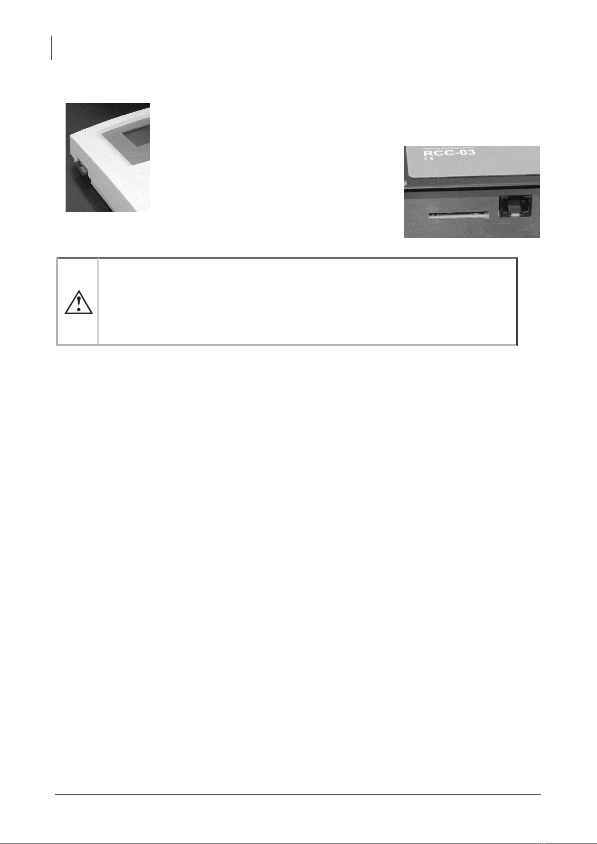
3.3 SD CARD
The RCC remote control is equipped with an SD (Secure Digital)-type memory
card reader. This card (supplied) is used for various functions described in this
manual. It allows, amongst others, the following functions: recording statistics,
updates, backups or restoration of configurations or adjustments. The filing
system used for the data is the FAT system (FAT16).
This card can be read using any standard SD
card reader.
As far as the RCC-03 is concerned, the use of the
SD card requires removing the remote control
since the access to the SD lies behind.
The system of the card reading is compatible with the following types of cards:
SD
SD HC
The system of the card reading is incompatible with the following types of cards:
SD XC
Cards of more than 32 GB
RCC-02
RCC-03

Studer Innotec SA
RCC-02/-03
User manual V4.4.0 11
4CONNECTION
The RCC-02 remote control must be firmly fastened using 3 screws on a flat support. The remote
control RCC-03 is meant to be integrated. It must be mounted by means of 4 screws (not supplied)
on a flat place without any mechanical constraints to the front plate. Once the RCC remote control
is fastened it can be connected to the inverter using the authorized cable only. If the cable is
damaged or if a socket is detached, the cable must not be connected since this can lead the whole
installation to malfunction.
A maximum of 3 remote controls can be connected to one unit.
4.1 SERIES CONNECTION
Devices in the Xtender series are equipped with a proprietary communication bus for data
exchange, configuration and updating of the system. Series connection is obtained by linking the
devices with the provided communication cables. This way a serial bus is created where the
terminations must be activated on the units on both ends.
Each device is equipped with a switch offering to choose between open "O" and terminated "T". By
default all terminations are activated on each Studer Innotec product. The devices at the end of the
line must be set on "T" (one cable) and all the others on "O" (two cables).
A wrong setting of the terminations can lead to an erratic running of the
installation or impede its updating.
The remote control must never be placed in between two devices connected
to the battery (Xtender, VarioTrack, VarioString).
Exemple of an installation with indicated terminations.

Studer Innotec SA
RCC-02/-03
12 V4.4.0 User manual
4.1.1 RCC-02
RCC-02 termination activated (position T)
RCC-02 termination deactivated (position O)
4.1.2 RCC-03
RCC-03 termination activated
(left position)
RCC-03 termination deactivated
(right position)
4.1.3 Xtender XTH
To activate the termination on the Xtender, move the two mini-switches to position T, and to
deactivate it, move them downwards to position O.
4.1.4 Xtender XTM
On an Xtender type XTM, to activate the termination, put the mini-switch on position T, to deactivate
it, move it to the right on position O.

Studer Innotec SA
RCC-02/-03
User manual V4.4.0 13
4.1.5 Xtender XTS
XTS termination activated (position T)
XTS termination deactivated (position O)
4.1.6 VarioString
VarioString termination activated (left position)
VarioString termination deactivated
(right position)
4.1.7 VarioTrack
VarioTrack termination activated (position T)
VarioTrack termination deactivated
(position O)
4.1.8 BSP
BSP termination activated (position T)
BSP termination deactivated (position O)


Studer Innotec SA
RCC-02/-03
16 V4.4.0 User manual
6QUICK START GUIDE
The remote control RCC gives you access to a many settings possibilities. However, in most cases the
setting of two parameters only is required for the perfect running of your installation.
6.1 SETTING OF THE LANGUAGE
To begin, set your remote control RCC for a display of the information in English.
The basic display is:
Press 1 time on the key “arrow downwards” to display the
following screen:
Once beyond this screen you can come back to it by means
of the key ”arrow upwards”.
Press the key SET to enter the remote control settings. The
screen of the language choice appears.
Press once more the key SET to modify the current language.
The language then appears in reverse video.
With the keys “arrow upwards” and “arrow downwards” choose the language you wish. Then
validate your choice by means of the key SET (OK).
We can now leave the setting of the remote control with the key ESC.
6.2 ADAPTATION TO THE SOURCE
It is a matter of indicating to the Xtender the power available to charge the batteries and to supply
the users.
In order to adapt your installation to the source it is connected to, proceed as follows:
The basic display is:
Press 2 times on the key “arrow downwards” to display the
following screen:
Once beyond this screen you can come back to it by means
of the key ”arrow upwards”.
Press the key SET to access to the settings.
Then again on the key SET to access to the basic parameters.
Other manuals for RCC-02
4
This manual suits for next models
1
Table of contents


