Studer TO A80 User manual
STUDEFr
PROTESSIONAL AUDIO EQUIPMENT
Althardstrasse 30
CH-8105 Regensdorf / Switzerland
Telephone +41 1 870 75 11
Telefax +41 1 840 47 37
Tlx 825 BB7 sti ch

5TI.'DER
;re
$;W,
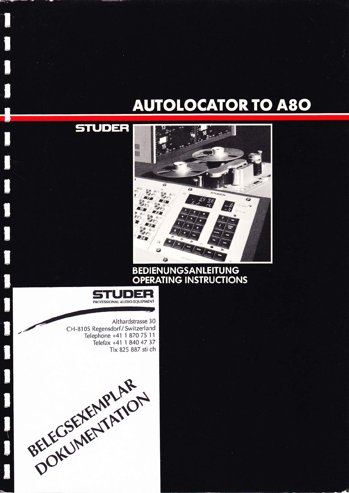
AUTOLOCATOR.
TOASO
BEDIENUNGSANLEITUNG
OPERATI NG I NSTRUCTI ONS
t8: :: w8"
Wtl
ld-;,,'
'1 /
71
-/ (>
/*
@,€l
&lw
i*
I
l!
tSt*x t

s'rrttDtrlR AUTOLOCATOR/A8O
I NHALTSV ERZE I CHN I STABLE OF CONTENTS Sei te
Page
SECTION 1ALLGEMEiNES GENERAL 1/1
1.1
1.2
1 .2.1
1 .2.2
1a
1.3.1
1 .3.2
Einleitung
Technische Daten
Ei genschaften
Abmes s ungen
Bestel 1 i nformati onen
Autolocator und Interface
Gehäuse, Stative
I ntroducti on
Technical specifications
Featu res
Di mens i ons
0rdering information
Autolocator and interface
Housi ng, stands
1/1
1/1
1/1
1/2
1/3
1/3
1/4
SECTION 2 I NB ETRi IBNAHME START-U P2/1
SECTION 3KURZB ESCHRE I BUNG QUICK-REFERENCE DESCRIPTION 3/1
a1
J. '
3.2
3.3
Anze i gen
Bed i enun gs tasten
Abspeichern der Einlaufkurve
Di sp1 ays
Funct i on
Storing a
keys
braki ng curve
3/1
3/2
3/4
SECTION 4BED I ENUNGSANLE lTUNG OPERATlNG INSTRUCTIONS 4/1
SECTION 5 ANHANG APPEND I X5/1
SECTION 6SCHEMATA SCHEMATI CS 6/1
SECTION 7 ERSATZTE I L E SPARE PARTS 7 /1
Prepared and edited by
STUDER- REVOX
Technical documentat.ion
Al thardstrasse 1 0
CH-B'1 05 Regensdorf-Zuri ch
l,Je reserve the right to make alterations
Copyright by WiI1i Studer
Printed in Switzerland
Order number 23.278.982

5T['DtrR AUTOLOCATOR/A8O
WORLDWI DE DISTRI BUTION EFFECTIVE MAI 1982
Switzerland: STUDER INTERNATIONAL AG
Althardstrasse 1 0
CH-8 1 05 Regensdorf
Phone: (01 ) 840 29 60
Telex: 58489 stui ch
EUROPE FAR EAST
Germany: STUDER FEVOX GMbH
Studiotechni k
Talstrasse 7
D-7821 Löffingen
Phone: 0765411021
f e.ex. 772211 8 rvox d
Hong Kong STUDER REVOX FAR EAST LTD
Sth Floor, Parklane Building
233-235 Oueen's Road, Central
Hong Kong
Phone: 5 - 45 96 BB I 5 - 44 13 10 / 5 - 4599 24
Telex: 601 85 srfel hx
Austria STUDER REVOX WIEN GES. IV.B.H.
Ludwiggasse 4
A-1 180 Wien
Phone: (0200) 47 33 09 I 47 3465
Telex: 07l5275sIudr a
Japan KAWAMU RA ELECTR I CAL LABORATORY
No. 34,Yarai - cho
Shinjuku - ku
Tokyo 162
Phone: (03) 260-0401
Telex. j22748zigzag
Cables: zigzag tokyo
France: STUDER FRANCE S.A.R.L
12 - 14, rue Desnouettes
F-7501 5 Paris
Phone: 533 58 58 +
Telex: studer 204744t
Austral ra: SYNTEC INTERNATIONAL PTY LTD
P.O. Box 165
North Sydney
Australia 2060
Phone : 4064700,4064551,4064627
Telex: 70570 syntec
Italy: STUDER ITALIANA
Viale CamPania 39
l-201 33 Milano
Phone: 73 84751 I 52 I 53
Telex: 335230 audiom
Cables: beppatomi I milano NORTH AND SOUTH AMERICA
United Kingdom: F.W.O. BAUCH LIMITED
49 Theobald Street
Boreham Wood, Herts WDO 4 RZ
Phone: 01 -953 00 91
febx. 27502 bauch g
Cables: bauch borehamwood
Ca nada: STUDER REVOX CANADA LTD
'14, Banigan Drive
Toronto 17, Ontario M4H 1E9
Phone: (416) 423-2831
Telex: 06-2331 0 studer tor
I
I
USA: STUDER REVOX AMERICA INC,
1425 Elm Hill Pike
Nashvi I le, Tennessee 372 1 0
Phone: (6'1 5) 254 - 5651
Telex: 065230/554453 studer nas
AFRICA
Hepublic of STUDER REVOX SOUTH AFRICA (PTY.) LTD Brazil: CENTELEC
South Af rica: P.O. Box 31282 Equipamentos e Sistemas Electronicos Ltd
Braamfontein 2017 (Johannesburg) Av. Ataulfo de Paiva 13511110
22440 Rio de Janeiro - RJ
phone: 35 .90j6177 Phone: (021 I 259 36 99
Telex: 4-2240i Telex: 2130842 cosl br
Cables: revox hifi johannesburg
23.050.582
t

sTUDtrR AUTOLOCATOR/A80
SICHERHEIT UND ERSTE HILFE SAFEWAND FIRSTAID SEcURITE ET PREMIERS SECOURS
SICHERHEIT
Durr,h Entfernen von Gehäuseteilen. Ab-
schirmungen etc. werden stromführende
Teile freigelegt. Aus diesem Grunde müs-
sen die folgenden Sicherheitsvorschriften
unbedingt beachtet werden:
1. Eingriffe in ein Gerät
dürfen nur von Fachpersonal vorgenom-
men werden.
2.Yor Entfernen von Gehäuseteilen:
Gerät ausschalten und vom Netz trennen.
3. Bei geöffnetem Gerät:
- NeEteil- oder Motorkondensatoren mit
einem passenden Widerstand entladen.
- Bauteile grosser Leistung, wie Leistungs-
transistoren und -widerstände sowie
Magnetspulen ünd Wickelmotoren erst
nach dem Abkühlen berühren.
4.Servicearbeiten bei geöffnetem,
unterSpannung stehendem Gerät:
- Keine blanken Schaltungsteile berÜhren
- lsolierte Werkzeuge verwenden
- Metallene Halbleitergehäuse nicht be-
rühren, da sie hohe Spannungen aufwei-
sen können.
ERSTE HILFE (bei Stromunfällen)
1. Bei einem Stromunfall die betrof-
fene Person raschmöglichst vom
Strom trennen:
- Durch Ausschalten des Gerätes
- Ausziehen oder Unterbrechen der Ne?-
zuleitung
- Betroffene Person mit isolierendem Ma-
terial (Holz. Kunstoff) von der Gefahren-
quelle wegstossen
- Nacheinem Stromunfall sollte immerein
Arzt aufgesucht werden.
ACHTUNG
EINE UNTER SPANNUNG STEHENDE PER-
SON DARF NICHT BERÜHRT WERDEN.
SIE KÖNNEN DABEI SELBST ELEKTRI.
SIERT WERDENI
2. Bei Bewusstlosigkeit des Verun-
fallten:
- Puls kontrollieren.
- bei ausgeseEterAtmung künstlich beat-
men,
- Seitenlagerung des Verunfallten und
Arzt verständigen.
SAFETY
There are no user serviceable components
inside the equipment, live parts are laid
open when removing protective covers
and shieldings. lt is essential therefore to
ensure that the subsequent safety rules are
strictly observed when performing service
work or repairs.
1. Servicing of electronic equipment
must be performed by qualified personnel
only.
2. Before removing covers:
Switch off the equipment and unplug the
mains cable,
3. When the equipment is oPen:
- Discharge power supply- and motor
capacitors through a suitable resistor.
- Components, that carry heavy electrical
loads, such as power transistors and
resistors as well as solenoid coils and
motors should not be touched before a
cooling off interval, as a precaution to
avoid burns.
4. Servicing unprotected and opera-
ting equipment:
- Never touch bare wires or circuitry
- Use insulated tools only
- Nevertouch metal semiconductorcases
because they may carry l-righ voltages.
FIRST AID (in case of electric shock)
1. Separate the person as quickly as
possible from the electric power
source:
- by switching off the equipment,
- unplugging or disconnecting the mains
cable,
- pushing the person away from the
power source by using dry insulating
material (such as wood or plastic).
- After having sustained an electric shock,
always consult a doctor.
WARNING:
DO NOT IOUCH THE PERSON OR HIS
CLOTHING BEFORE POWER IS TURNED
OFF, OTHERWISE YOU STAND THE RISK
OF SUSTAINING AN ELECTRIC SHOCK AS
WELLI
2. lf the person is unconscious
- Check the pulse.
- reanimate the perbon if respiration is
poor,
- laythe body down and turn itto one side.
call for a doctor immediately.
SEcURITE
Si les couvercles de protection sont en-
lev6s, les parties de l'appareil qui sont sous
tension ne sont plus prot6g6es. ll est donc
d'une n6cessitöe absolue de suivre les in-
structions suivantes:
l. Les intervensions dans les appa-
reils 6lectriques
doivent 6tre faites uniquement que par du
personnel qualifi6
2. Avant d'enlever les couvercles de
protection:
Couper l'interrupteur principal et d6bran-
cher le cäble secteur.
3. Apräs avoir enlev6 les couvercles
de protection:
- Les condensateurs de I'alimentation et
des moteurs doivent ötre d6charg6s ä
l'aide d'une r6sistance appropri6e.
- ll est prudent de laisser refroidir les com-
posants de haute puissance, par ex.:
transistors de puissance, r6sistances de
puissances de möme que des 6lectro-
aimants et les moteurs de bobinage.
4. S'il faut que I'appareil soit sous
tension pendent les r6glages in-
ternes:
- Ne jamais toucher les circuits non isol6s
- Travarller seulement avec des outils
isolös
PREMIERS SECOURS (en cas d'6lectro-
cution)
1. Si Ia personne est dans l'impossibi-
lit6 de se Iib6rer:
- Couper l'interrupteur principal
- Couper le courant
- Repousser la personne de I'appareil ä
l'aide d'un objet en matiöre non conduc-
trice (matiöre plastique ou bois)
- Aprös une 6lectrocution, consulter un
m6decin.
ATTENTION
NE JAMAIS TOUCHER UNE PERSONNE
OUI EST SOUS TENSION, SOUS PEINE DE
SUBIR EGALEMENT UNE ELECTROCU-
TION!
2. En cas de perte de connaissance de
la personne 6lectrocut6e:
- Controller le pouls
- Si n6cessaire, pratiquer la respiration
aftificielle
- Mettre l'accident6 sur le cot6 lat6rale et
consulter un m6decin.


5T['DtrR AUTOLOCATOR/A8O sEciloN 1/1
I. ALLGEMEINES
1.1
Ei nl ei tung
Während einer Session ist es wichtig,
dass speditiv gearbeitet werden kann
und nicht unnötig Zeit verschwendet
wird mit mühsamen Bandpositionierungs-
vorgängen, wenn ein Insert mehrmals
wiederholt werden muss. Die Studer
Studiobandmasch inen erhiel ten des-
halb schon relativ friih einen Zero
Locator, mit dem die Bandstelle mit
Zählerstand 0 auf einen einzigen
Tastendruck sofort angefahren werden
kann. Diese Ejnrichtung vereinfacht
den Suchvorgang nach einer gewünschten
Bandstel l e erhebl i ch. Der Nachtei l des
Zero Locators ist, dass der Bandzähler
bei jeder Bandstelle, die man später
anfahren möchte, auf 0 gesetzt werden
muss. Dadurch qeht der Ueberblick über
die Zeitverhäl tnisse einer Produktion
verl oren.
Es 1ag daher nahe, ein Gerät zu ent-
wickeln, dass mehrere Bandadressen
gleichzeitig speichert und erweiterte
Bedienungsmög1 i chkei ten wi e das Pro-
grammieren von Repeti tionsschleifen
mit und ohne Vorhörmögl.ichkeit, sowie
rasches und übersicht'liches Address
Handl ing aufweist. Der Studer Auto-
locator zu A80 und AB00 erfüllt diese
Forderungen:
1.2
Teähnische Daten
1. GENERAL
1.'l
I n trodu ct i on
When an insert must be repeated sever-
al times during a recording session it
is important that the operator can
work efficiently, i.e. without wasting
time by iaboriously repositioning the
tape. For this reason, Studer studio
tape recorders have been equipped at
a relatively early stage with a zero
locator feature through which the tape
address corresponding to the counter
reading zero can be immediately
searched with the push of a single
button. This feature greatly simpli-
fies the search for a specific tape
address. The djsadvantage of the zero
locator, however, is that the counter
must be reset to zero for each addi-
tional tape address to be searched.
As a result, it is difficult to keep
track of the playing time in a pro-
gram.
The obvious solution was to deveiop a
device that is capable of storing
multiple tape addresses and which fea-
tures extended operator facil ities
such as programming of repeated loops
with and without prelistening as well
as quick and simple handling of ad-
dresses. The Studer autolocator for
the AB0 and AB00 fu11y meets these
requi rements.
t.L
Technical specifications
1.2.1
EJlEi-schaften
- Laufwerkfernbedienung mit optischer
Rijckmel dung
- 20 Adressspeicher, 16 davon gepuffert
- Schleifenprogrammierung mit und
ohne Vorhörmögl ichkeit
- Anzeigen für Bandzähler, Locate
Address und aktuelle Schleifen-
regi ster
- Einfache Transfermögl ichkeiten für
Bandadressen:
Bandzähler->Locate Address und
umgekehrt
- Tape transport remote control with
visual feedback
- 20 address registers, 16 of which
are buffered
- Loop programming with and without
pre-1 i steni ng
- Displays for tape counter, Iocate
address and current loop registers
- Simple transfer of tape addresses:
Tape counter--->locate address
and vice versa
1.2.1
F6äT[res

STTJDtrR AUTOLOCATOR/A8O SECTION 1/2
1.2.2 1.2.2
ÄEnEssungen D'iTE-nsi ons
Fig. I .1 Fig. 1.2
Bedienungseinheit Autolocator Interface
Control unit Autolocator interface
Fig. 1.3 Fig' 1.4
Ti schgehäuse Stat i ve
Table cabinet Stands
Alle Studer Fernbedienungen sind mo-
du l ar aufgebaut. Di e schmal ste Steuer-
einheit besteht aus einem "Studer
Standard Modul" mit festgelegten Front-
plattenabmessungen. Die Breite einer
grösseren Frontplatte ist immer ein
ganzzahliges Vielfaches von der Breite
e'ines Standard Moduls" hingegen bleibt
die Frontplattenhöhe konstant.
Frontplattenabmessungen s ind durch
die Anzahl Standard Module genau de-
fi ni ert.
Abmessungen eines Studer Standard
Modul s:
Höhe :190mm
Breite : 40.6mm
Bl ind-Panels
Blind-Panels dienen zur Abdeckung von
LeerstelIen in nicht vo11ständig be-
setzten Fernsteuerungsstati ven :
All Studer remote control units are
for modular mounting. The smallest
unit consists of one "Studer standard
module" with a front panel of defined
dimensions. The width of Ionger front
panels is therefore always a whole
number multiple of the width of a
standard module, whereas the panel
height remains constant. Front panel
dimensions are precisely defined by
the number of standard modules.
Dimensions of one Studer standard
modul e:
Height : 190mm
I,lidth :40.6mm
FiIier panels
The filler panels are used to cover
blanks in not completely occupied
remote control stands:
Size: 1 module 1.038.341.00
2 modu l es 1 .038.342.00
3 modules 1.038.343.00
Grösse: 1 Modul
2 Module
3 Modul e
.038.341.00
.038. 342.00
.038.343.00
,493
5T[JDtrR AUTOLOCATOR/A8O sEcfloN 1/3
Frontplattenabmessungen der wichti gsten
Studer Fernsteuerungen in Modulen the most important remote
units in modules
Size of
con trol
Autol ocator
Vari speed
B Kanal Audio
16 Kanal Audio
24 Kanal Audio
TLS Programmer
Code Kanal
4 Module
2 Module
3 Module
5 Modu'l e
7 Modul e
B Modul e
1 Modul
Auto l ocator
Vari speed
B channel audio
16 channel aud'io
24 channel audio
TLS Programmer
Code channel
4 modu l es
2 modules
3 modules
5 modu l es
7 modules
B modules
1 module
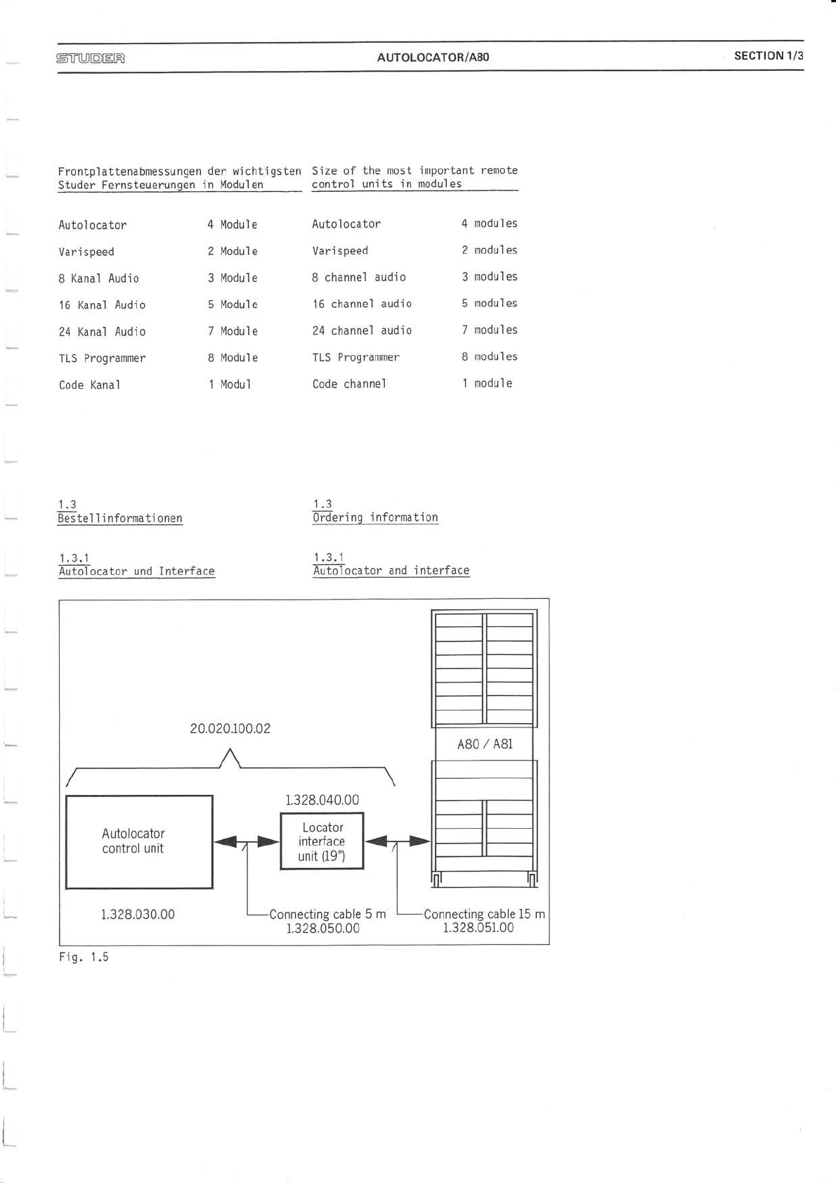
1.3
BestelI informationen
1.3.1
ilutol ocator und I nterf ace
t.J
0rdering information
.i al
Äuilol ocator and i nterface
20.020.r00.02
1.328.030.00 cting cable 5 mConnecting cable 15 m
1.328.051.00
r.328,050.00
1.328.040.00
Autolocator
control unit
Fis. 1.5
!
L
I
l*
t
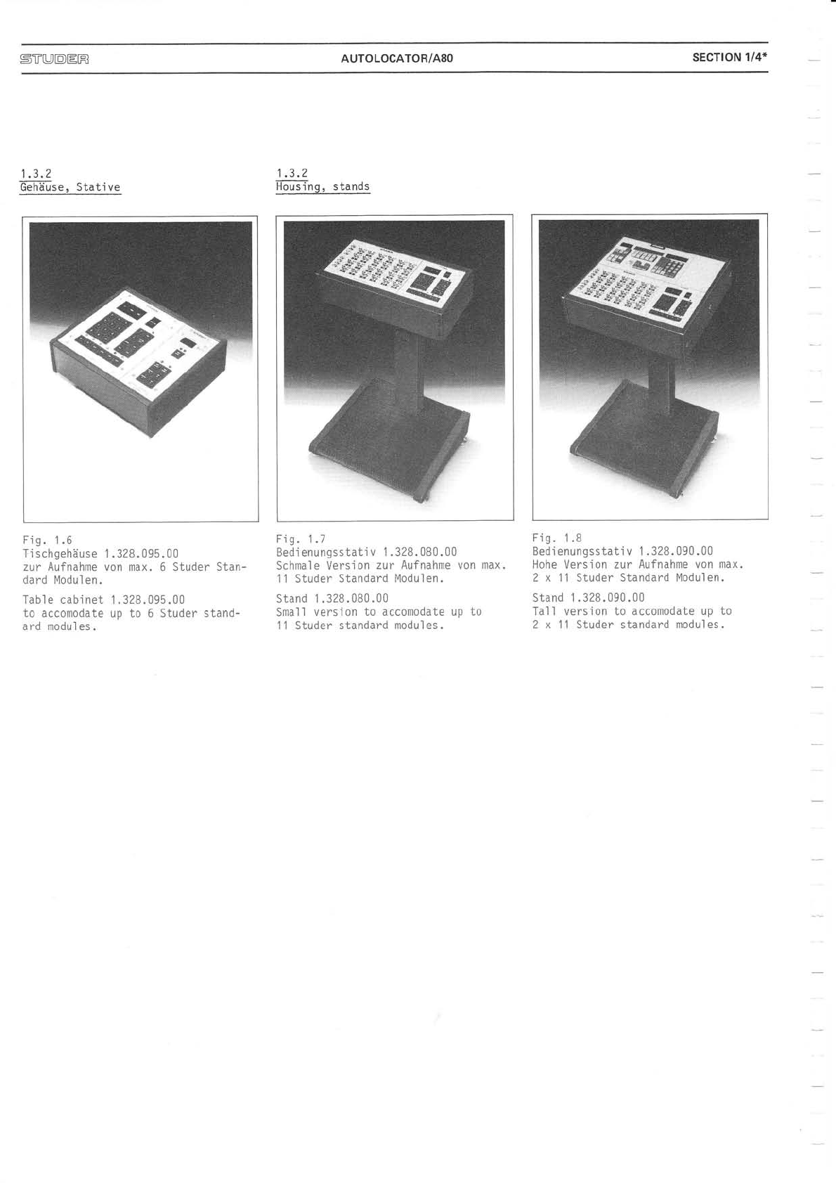
5TT'DtrR AUTOLOCATOR/A8O sEcrtoN 1/4*
1.3.2
GIäuse Stati ve
Fig. 1.6
Ti schgehäuse 1 .328.095.00
zur Aufnahme von max. 6 Studer Stan-
dard Modulen.
Table cabinet 1.328.095.00
to accomodate up to 6 Studer stand-
ard modul es.
1 .3.2
Fou-si ng, stands
Fig. 1.7
Bedienungsstativ 1 . 328. 080.00
Schmale Version zur Aufnahme von max.
11 Studer Standard Modulen.
Stand 1.328.080.00
Small version to accomodate up to
11 Studer standard modules.
Fig. 1.8
Bedienungsstativ 1 .328.090.00
Hohe Version zur Aufnahme von max.
2 x 11 Studer Standard Modulen.
Stand 1.328.090.00
Tall version to accomodate up to
2 x 11 Studer standard modules.

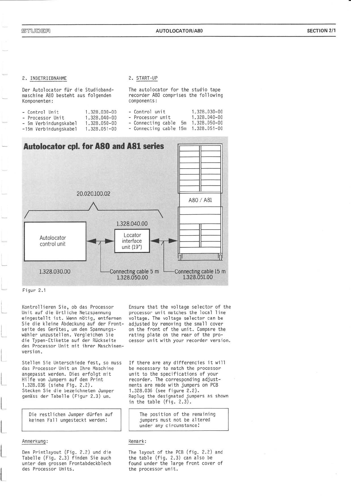
5TUDtrR AUTOLOCATOR/A8O sEcrtoN 2/1
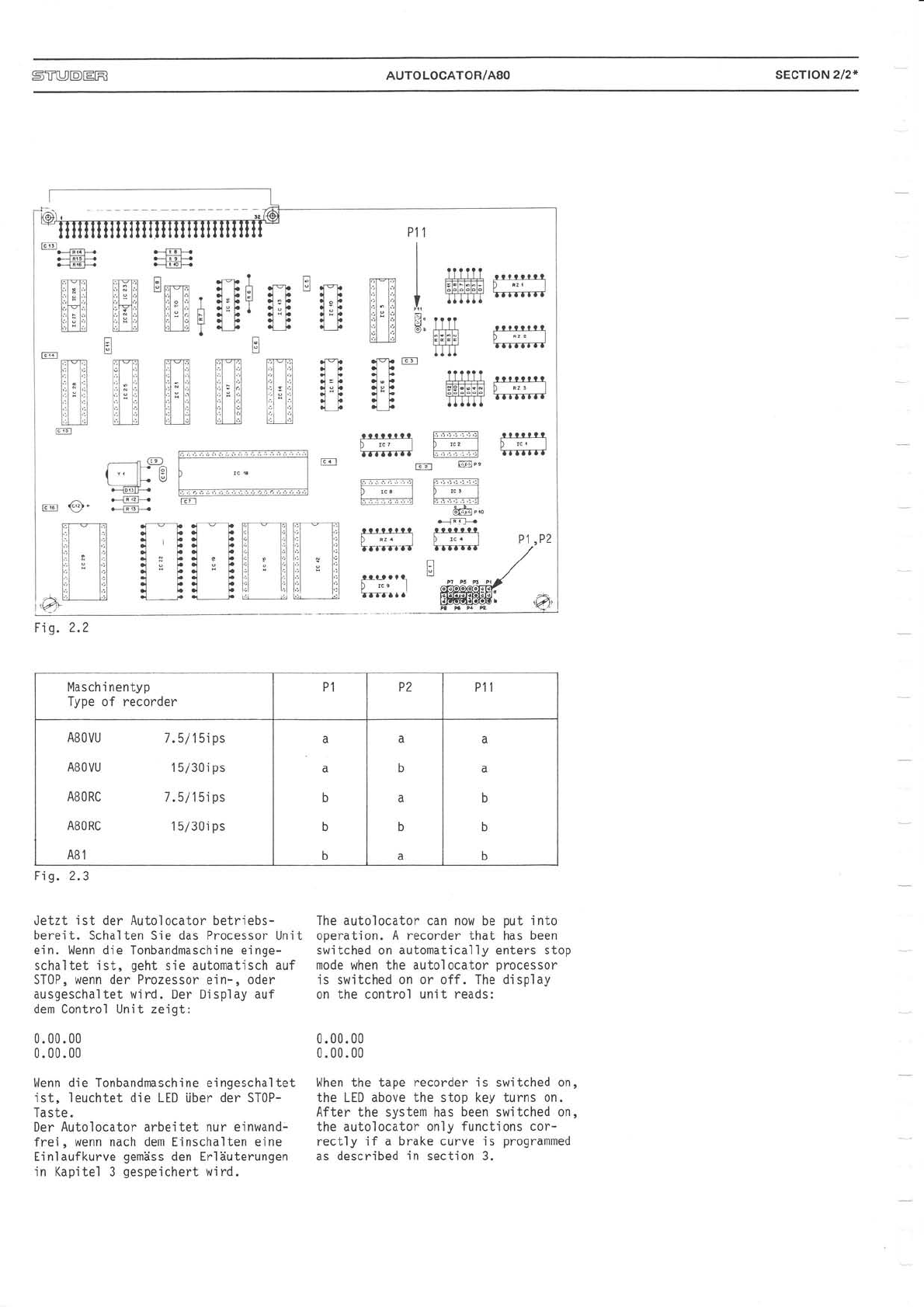
2. INBETRIEBNAHME
Der Autolocator fiir die Studioband-
maschine AB0 besteht aus folgenden
Komponenten:
- Control Unit 1.328.030-00
- Processor Un it 1 .328.040-00
- 5m Verbindungskabel 1.328.050-00
-15m Verbindungskabel 1.328.051-00
Anmerkung:
Den Printlayout (Fi9.2.2) und die
TabelIe (Fig. 2.3) finden Sie auch
unter dem grossen Frontabdeckblech
des Processor Units.
2. START-UP
The autolocator for the
recorder 480 compri ses
components :
- Control unit
- Processor unit
- Connecting cable 5m
- Connecti ng cabl e 'l 5m
studio tape
the fol 1 owing
1.328.030-00
1 .328.040-00
1.328.050-00
't .328.051-00
l
I
I
I
i
t
t
t
lutolocator,, G$l;.fOr, fiS$,änd',,*8'il
Figur 2.1
Kontrollieren Sie, ob das Processor
Unit auf die örtliche Netzspannung
eingestellt ist. Wenn nötig, entfernen
Sie die kleine Abdeckung auf der Front-
seite des Gerätes, um den Spannungs-
wähler umzustellen. Vergleichen Sie
die Typen-Etikette auf der Rijckseite
des Processor Unit mit ihrer Maschinen-
vers i on .
Stellen Sie Unterschiede fest, so muss
das Processor Unit an Ihre Maschine
angepasst werden. Dies erfolgt mit
Hilfe von Jumpern auf dem Print
1.328.036 (siehe Fig. 2.2).
Stecken Sie die bezeichneten Jumper
gemäss der Tabelle (Figur 2.3) um.
Die restlichen Jumper dürfen auf
keinen Fall umgesteckt werdenl
Ensure that the voltage selector of the
processor unit matches the local line
voltage. The voltage selector can be
adjusted by removing the small cover
on the front of the unit. Compare the
rating plate on the rear of the pro-
cessor unit with your recorder version.
If there are any differencies it will
be necessary to match the processor
unit to the specifications of your
recorder. The corresponding adjust-
ments are made with jumpers on PCB
1.328.036 (see figure 2.2).
Replug the designated jumpers as shown
in the table (fig. 2.3).
The position of the remaining
jumpers must not be altered
under any circumstance,l
Remark:
The layout of the PCB (fig. 2.2) and
the table (fig.2.3) can also be
found under the large front cover of
the processor unit.
Autolocator
control unit
STUDtrR AUTOLOCATOR/A8O sEcTtoN 2/2*
FlFli E"*", l-N Ä *-, B o lrlTf
;l,L;L -i:;l"L: r i,Fhl t"[ 1"t ]:i ;l
I'811 lli[L üt=F'I'F l=F t;l'l
L_ lr.l f,, Itl I d b I b I F il r'
?ltilt
l:l:l:l:l:l;
t,il,tlt
ml
-t.t.t.t
I.III
l?llll
Fl:l:l:l:El
:ilTTI
F *--l
l:'" r' :1 ,
rl W""
l: !) n ir .:-: ?J
öö"-
.--]F!l{
p '..
Tanffi
F
t9l
Maschi nentyp
Type of recorder P1 P2 Pl1
AB0VU 7.5/ 1 5i ps
A80VU 1 5/30i ps
AB0RC 7.5/1 5i ps
A80RC 1 5/30i ps
481
a
a
b
b
b
a
b
b
a
Fi1. 2.3
Fig.2.2
Jetzt ist der Autolocator betriebs-
bereit. Schalten Sie das Processor Unit
ein. Wenn die Tonbandmaschine einge-
schaltet ist, geht sie automatisch auf
ST0P, wenn der Prozessor ein-, oder
ausgeschaltet wird. Der Display auf
dem Control Unit zeigt:
0.00.00
0.00.00
[^lenn d'ie Tonbandmaschine eingeschaltet
ist, leuchtet die LED über der ST0P-
Taste.
Der Autolocator arbeitet nur einwand-
frei, wenn nach dem Einschalten eine
Einlaufkurve gemäss den Er1äuterungen
in Kapitel 3 gespeichert wird.
The autolocator can now be put into
operation. A recorder that has been
switched on automatically enters stop
mode when the auto'locator processor
'is switched on or off. The display
on the control unit reads:
0.00.00
0.00.00
When the tape recorderi s switched on,
the LED above the stop key turns on.
After the system has been switched on,
the autolocator only functions cor-
rectly if a brake curve is programmed
as described in sect.ion 3.


STUIOIEIF] AUTOLOCATOR/A8O sEcTloN 3/1
t
t
t_
L
L
L
L
L
t
I
3. KURZBESCHREIBUNG 3. QUlCK-REFERENCE DESCRIPTI0N
3.1 3.1
Aruei gen DTlpl ays
TAPE-POS TAPE-POS
TeigT-den momentanen Bandzählerstand. DTsFiays the current tape counter
read i ng .
LOCATE ADDRESS LOCATE ADDRESS
7eG-ATTE-Elngaben oder die Ziel- DisFfits all-Tnputs or the locate
adresse fijr RLB, LOC oder REP. address for the functions RLB, L$C or
REP.
START REGISTTR START REGISTER
NummeFlEs-STärtregisters für die Nurn6er-ofsTart register seiected for
Repetitionsschleife. the repeated 1oop.
END REGISTER END REGISTER
NunrnreF-aesTndregisters für die Num6äFof end register selected for
Repetitionsschleife. the repeated 1oop.
LOC-ACT LOC-ACT
IiuilTet in folgenden Fällen: TTTü-minateA under the following con-
ditions:
- nach ST0 und RCL: - After ST0 and RCL:
bis ein Register eingegeben, oder until a register number is entered
die Taste CLR gedrückt wird. or the CLR key is pressed.
- nach LOC und RLB: - After LOC and RLB:
bis die Zielposition L0CATE ADDRESS until the locate address is reached.
erreicht ist.
- in einer REP-Schleife: - In a REP loop:
bis die Schleife mit CLR abgebro- until the loop is cancelled with
chen wird. CLR.
LOCATE _ ADDRESS
78
46
2
l
,0 CLR
DISPLAY
END REGISTER
DISPLAY
START REGISTER
LOCATO.R
COI\4I\4AND SWITCHES
BACK INDICATION
TAPE TRANSPORT
TAPE TRANSPORT
COMIVIAND SWITCHES
Fig. 3.1

5TT[JDtrR AUTOLOCATOR/A8O SECTION 3/2
B1 i nkt, wenn:
- Eine überwachte Verbindung fehlt.
- Der Prozessor einen Fehler aufweist.
Schalten Sie das Interface im Falle
eines Prozessor-Fehlers aus und ein
um einen Restart des Programmes ein-
zuleiten.
3.2
EI'i enungstasten
RES ET
Sffi den Bandzähler auf der AB0 und
den Display TAPE-POS auf 0.
0 -L0c
AkTlviert den Zero-Locator in der A80,
die Maschine kehrt auf 0 zurück.
Die beiden obigen Tasten sind auch bei
ausgeschal tetem Autol ocator akti v.
PLAY kann nicht vorgewählt werden.
Fl ashes if:
-A mon'itored connection is missing,
-a processor error is detected,
In case of a processor error, switch
the processor unit off and on again
to restart the program.
3.2
Filrrction keys
RESET
STs-the tape counter of the AB0 and
the TAPE-P0S display to address 0.
0 -L0c
I?TT-vates the zero locator in the A80.
The recorder rewinds to 0.
These two keys remain active when the
autolocator is switched off.
PLAY cannot be preselected.
Kopiert den Inhalt
nach TAPE-P0S. von L0CATE ADDRESS Copies the
into TAPE content of LOCATE ADDRESS
Pos.
Kopiert den Inhalt
LOCATE ADDRESS. TAPE-POS. nach Copies
LOCATE the content of TAPE-POS into
ADDRESS.
trtr
Speichert den Inhalt von LOCATE ADDRESS
im angewählten Register (0..9 resp.
-0..-9 : 20 mögl ichen Registern).
Stores the content of LOCATE ADDRESS
in selected register (0..9 or -0 ..-9
: 20 selectable registers).
trtr
Zeigt den Inhalt des angewäh1ten
Registers auf dem Display LOCATE
ADDRESS an.
Speichert den momentanen Bandzähler-
stand während der PLAY Funktion in
eines der positiven Register 0..9.
Indicates the content of selected reg-
ister on L0CATE ADDRESS display.
Stores the current tape counter reading
during PLAY function in one of the
positive registers 0..9.
ACHTUNG
Die positiven Speicher werden mit
ST0RE CUE überschriebenl
CAUT I ON
Tfre positive registers are over-
written by the ST0RE CUE functionl

sTTUDtrR AUTOLOCATOR/A8O sEcTloN 3/3
r--l
I pr-nv I
L_l
Die Masch'ine fährt die in LOCATE
ADDRESS angezeigte Adresse an. PLAY
kann vorqewählt werden.
t---l
I pr-rv I
L_l
Die Maschine parkiert mit einem
programmierbaren Vorhal t zwischen
1 und 9 Sekunden vor der Adresse, die
in L0CATE ADDRESS angezeigt wird. Nach
dem Einschalten des Interface wird
der Vorhalt automatisch auf 4Sekunden
gesetzt. PLAY kann vorgewäh1t werden.
trtrtr
Korrigiert den Vorhalt im oben er-
wähnten Bereich.
The recorder advances to the address
'indicated on the L0CATE ADDRESS dis-
play. The PLAY function can be pre-
sel ected,
The recorder parks with the specified
rolIback offset (programmable between
1 and 9 seconds) ahead of the address
indicated on the LOCATE ADDRESS dis-
play. After the interface is switched
on, the rollback offset is automat-
ica11y initial ized to 4 seconds. The
PLAY function can be preselected.
Adjusts the ro'llback offset within the
specified time limits.
trtrtr
Wiederholung einer gewünschten Sequenz
'in ei ner Endl os- Schl ei fe. Repetition of a desired sequence in
an endless 1oop.
REPEATED LOOP
Fi g. 3.2

ST[JDtrR AUTOLOCATOR/A8O sEcTtoN 3/4*
INI€RRUPT AND BESTART
' -----)
INIENAUPT AND START
AT IHE STAET AODSESS
(STAAT OF LOOP MOOE
INIEBRUPT LOOP ANO\
PARK AT IHE START
ADDRE$ MINUS "418"
OFFSET
tr
tr ,:
l____r
lt UPOAIING OF START
ANO ENO ADDRESS
ENDS THE REPETITION MODE
Fig. 3.3
Nachdem eine Schleife programmiert After the loop has been programmed,
wurde, sind folgende Funktionen the following functions can be per-
möglich: formed:
3.3 3.3
ÄbTpeichern der Einlaufkurve STdring a braking curve
Jedesmal wenn der Prozessor einge- Every time the processor unit is
schaltet wird, muss jhm die Reaktions- switched on, it has to learn the
zeit der verwendeten Tonbandmaschine reaction time of the used tape record-
übermittelt werden, damit er optimal er to work proper'ly.
arbeiten kann.
Zu diesem Zweck wird eine Locate For this reason enter a tape address
Adresse eingegeben, die mindestens that is at least 3min. "away" from
3min. von der momentanen Bandposition the actual tape address, and locate
"entfernt fiegt", dann wird die einge- to this address. The address difference
gebene Adresse angefahren mit der of at least 3min. is necessary because
LOCATE-Taste. Der Abstand von 3min. the spooiing motors must reach their
ist nötig, damit die Wickelmotoren full winding speed during the locate
auf ihre vo1'le Umspulgeschwindigkeit procedure. 0nly then a satisfactory
kommen, denn nur dann wird eine zu- braking curve is atteined.
friedenstel l ende Ei n l aufcharakteri s-
tik erreicht.
Der Prozessor speichert die Einlauf- The processor will store the braking
kurve während des Locate-Vorganges curve automatically.
automatisch ab.
Vorgehen:
- Interface einschalten, - Switch on the processor unit.
- Adresse, die mindestens 3min. von - Enter an address, at least 3min.
der aktuellen Bandposition "ent- "away" from the actual tape position.
fernt ist", eingeben.
- LOC ST0 drl,icken. - DepreSs LOC and ST0.
lst die Bremscharakteristik nicht If the braking charakteristic is not
mehr optimal, weil z.B. die Bandge- satisfactory any longer, e.g. because
schwindigkeit geändert wurde, oder the tape speed has been changed or the
die Bandposition (Bandanfang, Bänd- tape position (start or end of tape)
ende) extrem geändert hat, kann eine has changed extremely, store a new
neue Einlaufkurve gespeichert werden braking curve according to the pro-
Procedure:
(Vorgehen wie oben). cudure above.


STUDtrR AUTOLOCATOR/A8O sEcrtoN 4/1
4. BEDIENUNGSANLEITUNG
Numeri sche Eingabetasten
A'l1e Eingaben werden auf dem Display
LOCATE ADDRESS angezeigt. Jede neu
eingegebene Ziffer schiebt die voran-
gehenden Ziffern um eine Stelle nach
links auf dem Display. Nach fünf ein-
gegebenen Ziffern sind alle weiteren
Eingaben wirkungslos, bis eine Funk-
tion wie ST0, RCL, CLR, LOC oder RLB
ausgeführt worden ist.
Beachte:
Eine eingegebene 0 als erste Ziffer
belegt ebenfalIs eine! StelIe in der
Anzeige.
= Vorzeichenwechsel
Dient zur Eingabe von negativen Adres-
sen oder zur Adressierung negativer
Register. Be'i der Eingabe einer Adresse
kann das Vorzeichen jederzeit ge-
wechselt werden. Bei der Adressierung
eines Registers muss das Vorzeichen
vor der Rdgisternummer eingegeben
werden.
Nochmaliges Drücken der Vorzeichen-
taste setzt ein irrtijmlich falsch ge-
wähltes Vorzeichen wieder zurück.
4. OPERATING INSTRUCTIONS
Numeric input keys
All entries are indicated on the L0-
CATE ADDRESS display. Each new digit
entered shifts the o1d display con-
tent to the left by one position.
After five digits have been entered,
no further input will be accepted
until a function such as ST0, RCL,
CLR, LOC or RLB has been performed.
Note:
A leading zero also occupies one pos-
'i tion on the display.
= Change sign key
For entering negative addresses or for
addressing negative registers. When
changing an address, the sign can be
changed at any time, However, when
selecting a register, the sign must be
entered before the register number.
An erroneously wrong chosen sign can
be corrected by pressing the change
sign key once morej.
= Clear
Setzt die Anzeige L0CATE ADDRESS auf 0.
Wenn die Maschine in einer Schle'ife
I äuft:
Die erste Betätigung von CLR bricht
die Schleife ab und Iöscht zu diesem
Zweck die beiden Registerdisplays.
Die zweite Betätigung von CLR setzt
die Anzeige LOCATE ADDRESS auf 0.
Nach RCL oder ST0:
CLR setzt die Anzeige LOCATE ADDRESS 0
und löscht das Display Start Register.
= C'l ear
Resets the LOCATE
VJhile the recorder
ADDRESS display to 0.
is executing a loop:
tJhen CLR is pressed for the first time,
the loop is terminated and the two
register displays are cleared.
When CLR is pressed for the second
time the LOCATE ADDRESS display is set
to 0.
After RCL or ST0:
CLR sets the L0CATE ADDRESS display
to 0 and clears the display start
register.
Table of contents
Other Studer Industrial Equipment manuals


