manuals.online logo
Brands
  1. Home
  2. •
  3. Brands
  4. •
  5. Virutex
  6. •
  7. Industrial Equipment
  8. •
  9. Virutex AK97NW User manual

Virutex AK97NW User manual

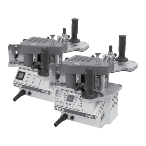
Perfilador motorizado
Motorized trimming unit
Unite d'arasage motorisée
AK97NW
MANUAL DE INSTRUCCIONES
OPERATING INSTRUCTIONS
MODE D’ EMPLOI
2
ESPAÑOL
PERFILADOR MOTORIZADO AK97NW
(Imágenes en página 5)
1. INSTRUCCIONES DE SEGURIDAD
Lea atentamente este MANUAL DE INS-
TRUCCIONES así como el FOLLETO DE
INSTRUCCIONES GENERALES DE SEGURI-
DAD adjunto, antes de empezar a trabajar
con la máquina.
- Asegúrese antes de enchufar la máquina que la tensión
de alimentación se corresponda con la indicada en la chapa
características.
- Mantener siempre las manos alejadas de las áreas de corte.
- Use siempre recambios originales VIRUTEX.
-Nousenuncacuchillasdefectuosasoenmalestadodecorte.
2. INSTRUCCIONES DE MONTAJE
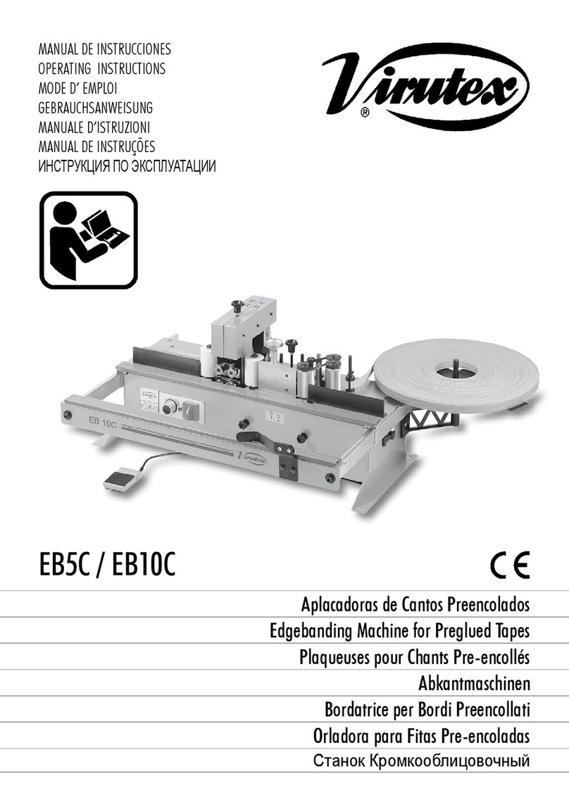
2.1 MONTAJE EN EB5C/EB10C
PERFILADOR MOTORIZADO REF. 5145545
Colocar el perfilador, aflojando los tornillos C (Fig. 1), para
que permitan su introducción en las guías, apretandolos de
nuevo una vez colocado pero sin bloquearlo.
Levantar el portacuchillas superior, para permitir el acceso
de la madera hasta los patines de apoyo D (Fig. 2). Apoyar
un tablero entre los dos rodillos encoladores 1 y 2 (Fig. 2),
y manteniéndolo en esta posición, aproximar el perfilador
motorizado hasta que los patines de apoyo hagan contacto
con la madera.
Apretar los tornillos C que sujetan todo el grupo.
2.2 MONTAJE EN MEB250A/PEB250TRC/PEB250TA
CONJUNTO PERFILADOR MOTORIZADO REF. 5046703
Conjunto formado por 1 perfilador AK97NW, 1 rodillo
izquierdo, 1 rodillo de salida y 2 prensores panel.
Para el montaje del perfilador en los modelos indicados
lea atentamente las instrucciones que se entregan con
este conjunto.
También puede consultar las instrucciones en vídeo en
nuestra web: www.virutex.es.
3. CARACTERISTICAS TÉCNICAS
Motor universal...............................................................50/60 Hz
Ø fresa...................................................................................36 mm
Espesor máximo del canto.....................................................1 mm
Grueso mínimo a cantear...................................................11 mm
Grueso máximo a cantear..................................................65 mm
Peso............................................................................................4,1 kg
4. REGULACIÓN DE LAS CUCHILLAS
Mediante el pomo E (Fig. 2) subir o bajar el portacuchillas
superior ajustandolo al grueso del tablero que vaya a
utilizar visualizandolo por la escala milimetrada A3 y el
indice B3 (Fig. 2 bis).
5. FUNCIONAMIENTO
Conecte el perfilador AK97NW directamente a la red eléc-
trica o la base preparada al efecto que se encuentra en la
parte trasera de la máquina, en caso que la haya, cuidando
que las características de la corriente correspondan a las
indicadas en la etiqueta del aparato. El perfilador, se pondrá
en marcha cuando el tablero pase entre los rodillos F (Fig. 2),
y se detendrá automáticamente cuando éste los abandone
una vez perfilados. El perfilador AK97NW, puede realizar
el perfilado hasta canto de 1 mm de espesor.
Desconecte el perfilador de la red eléctrica
antes de efectuar cualquiera de las ope-
raciones que se explican a continuación.
6. CAMBIO DE LAS CUCHILLAS
Retirar todas las protecciones que cubren el conjunto,
quitando para ello los tres tornillos I de cada lateral (Fig. 2).
MANUAL DE INSTRUCCIONES
OPERATING INSTRUCTIONS
MODE D'EMPLOI
página/page
seite
ESPAÑOL Perfilador motorizado AK97NW
2
ENGLISH AK97NW Motorized trimming unit
3
FRANÇAIS Unite d'arasage motorisée AK97NW
4
3
Quitar los tornillos Z que sujetan el conjunto de arrastre
sobre la polea W, y retirar éste (Fig. 4).
Quitar los tornillos M que sujetan las cuchillas (Fig. 3).
Retirar las cuchillas.
Las cuchillas tienen corte por los dos lados del diente, en una
delas caras (1 y2), por lo quepuede aprovecharse el segundo
corte antes de cambiarlas por otras nuevas, montando la
cuchilla inferior en el soporte superior, y viceversa (Fig. 3).
7. CAMBIO DE LAS CORREAS
Retirar las protecciones que cubren todo el conjunto, qui-
tando para ello los tres tornillos de cada lateral.
Retirar la correa dentada en mal estado, y reemplazarla por
otra original VIRUTEX, engranándola correctamente con los
dientes de la polea y sin forzarla (Fig. 4).
8. CAMBIO DE ESCOBILLAS
Desconectar el cable de conexión del perfilador
motorizado.
Extraer el perfilador motorizado de su alojamiento en la
máquina, desenroscando los tornillos.
Quitar los tornillos B1, del capuchón D1, retirando éste de
su alojamiento (Fig. 5).
Levantar los resortes C1 (Fig. 6), que presionan las
escobillas, y sustituirlas por otras originales VIRUTEX,
asegurándose que deslizen suavemente en el interior de
las guías.
Montar de nuevo el capuchón D1 en su alojamiento. Se
aconseja tener en marcha el perfilador 10 minutos sin
trabajar, para conseguir un mejor conformado de las
escobillas.
Si el colector presenta quemaduras o resaltes, se
recomienda hacerlo reparar en un servicio técnico
VIRUTEX.
Para esta operación no utilizar nunca papel esmeril.
9. GARANTÍA
Todas las máquinas VIRUTEX, tienen una garantía válida
de 12 meses a partir del dia de su suministro, quedando
excluidas todas las manipulaciones o daños ocasionados por
manejos inadecuados o por desgaste natural de la máquina.
Para cualquier reparación, dirigirse al Servicio Oficial de
Asistencia Técnica VIRUTEX.
VIRUTEX, se reserva el derecho de modificar sus productos
sin previo aviso.
ENGLISH
AK97NW TRIMMING UNIT
(Pictures in page 5)
1. SAFETY INSTRUCTIONS
Read these OPERATING INSTRUCTIONS
and the included GENERAL SAFETY INS-
TRUCTIONS LEAFLET carefully before using
the machine.
- Before connecting to the mains ensure that the supply
voltage corresponds that shown on the specification plate.
- Always keep hands away from the cutting zone.
- Always use original VIRUTEX spare parts.
- Never use damaged or worn blades.
2. ASSEMBLY INSTRUCTIONS
2.1 ASSEMBLY ON EB5C/EB10C
MOTORIZED TRIMMING UNIT REF. 5145545
Place the knife trimming station, loosening screws C (Fig. 1),
so that it can be fitted on the guide rails; tighten the screws
once it is in position, but do not let it to jam or be blocked.
Lift the upper knife holder unit to let insertion of the panel
up to the slide D (Fig. 2).
Place a panel between the two rollers 1 and 2 (Fig. 2), and
hold it in position; move the motorized trimming station
until the front slides of the trimmer makes contact with the
panel. Tighten the screws C that hold the trimming station.
2.2 ASSEMBLY ON MEB250A/PEB250TRC/PEB250TA
MOTORIZED TRIMMING UNIT SET REF. 5046703
Consistsof 1 AK97NWmotorized trimming unit, 1left roller,
1 exit roller, 2 pressers.
For the assembly of the trimming unit on these models
please read carefully the manual delivered with this set.
You can also find a video with these instructions on our
web site www.virutex.es.
3. TECHNICAL SPECIFICATIONS
Universal motor...............................................................50/60 Hz
Blade Ø..................................................................................36 mm
Maximumtapethickness........................................................1 mm
Minimumpanelthickness......................................................11mm
Maximumpanelthickness......................................................65mm
Weight........................................................................................4,1kg
4. BLADES ADJUSTMENT
Use knob E (Fig. 2) to raise or lower the upper blade holder
and adjust it to the thickness of the board to use, checking
it with the millimeter gauge A3 and index B3 (Fig. 2b).
5. OPERATION
Connect the trimming station AK97NW to the mains or to
the plug on the rear part of the edgebander, if any, bearing
4
in mind that voltage is the same as that indicated in the
machinenameplate. The trimmingstationwillstart working
when panel pass through among rolls F (Fig. 2) and will stop
after having finished this operation.
The AK97NW trimming unit can trim tapes up to 1 mm
thickness.
Disconnect the trimming station from the
electric system before performing any of the
operations herebelow mentioned.
5. REPLACEMENT OF KNIVES
Remove the guards that cover the entire unit; to do this,
remove the three screws I from each side (Fig. 2).
Remove the screws Z that hold the drag unit on the pulley
W, and remove this item (Fig. 4).
Remove the knives.
The knive cuts on both sides of the tooth (cuts, 1 and 2),
on one of its faces. Then, the second tooth cut can be used
before replacing the knives, mounting the lower knife on
the upper holder, and vice-versa (Fig. 3).
6. REPLACEMENT OF BELTS
Remove the guards that cover the entire unit; to do this,
remove the three screws from each side.
Removethetoothedbeltthatisinbad condtions, and replace
it with another original VIRUTEX belt. Fit it properly into the
teeth of the pulley without forcing it (Fig. 4).
7. REPLACEMENT OF BRUSHES
Disconneet the connection cable of the motorised
trimmer.
Remove the motorised trimmer from its housing in the
machine, loosening screws.
Remove screws B1 from the protector D1, removing the
latter from its housing and cover (Fig. 5).
Raise springs C1 (Fig. 6) which hold the brushes in place
and replace the brushes with VIRUTEX original spares,
ensuring that they move smoothly inside the guides.
Replace the cap D1. It is recommendable to leave the
trimmer running for 10 minutes without working to shape
the brushes better.
If any roughness or damage is observed on the collector,
we recommend you have it repaired at a VIRUTEX service
point.
Never use sandpaper for this operation.
8. GUARANTEE
All VIRUTEX machines are guaranteed for 12 months from
the date of supply, excluding any damage which is a result
of incorrect use or of natural wear and tear on the machine.
All repairs should be carried out by the official VIRUTEX
technical assistance service.
VIRUTEX reserves the right to modify its products without
prior notice.
FRANÇAIS
UNITÉ D'ARASAGE MOTORISÉE AK97NW
(Images sur la page 5)
1. INSTRUCTIONS DE SÉCURITÉ
Avant d'utiliser la machine, lisez attenti-
vement ce MANUEL D'INSTRUCTIONS et la
BROCHURE D'INSTRUCTIONS GÉNÉRALES
DE SÉCURITÉ qui vous sont fournis avec
cette machine.
- Avant de brancher la machine, s'assurer que la tension
d'alimentation correspond à celle indiquée sur la plaque
des caractéristiques.
- Maintenir toujours les mains éloignées des zones de coupe.
- Utiliser toujours des pièces de rechange d'origine VIRUTEX.
- Ne jamais utiliser de couteaux défectueux ou en mauvais
état.
2. INSTRUCTIONS DE MONTAGE
2.1 MONTAGE SUR EB5C/EB10C
UNITÉ D'ARASAGE MOTORISÉE RÉF. 5145545
Placer l'unité d'affleurage, en desserrant les vis C (Fig. 1),
pourqu'ellespermettent son introduction danslesglissières,
les resserrant une fois l'unité placée, mais sans la bloquer.
Lever le bloc de couteaux supérieur pour permettre l'accès
du bois jusqu'aux patins d'appui D (Fig. 2).
Appliquer un panneau entre les deux rouleaux d'encollage
1 et 2 (Fig. 2), et en le maintenant dans cette position,
approcher l'unité d'affleurage motorisée jusqu'à ce que les
patins d'appui entrent en contact avec le bois. Serrer les
vis C qui fixent tout le groupe.
2.2
MONTAGE SUR MEB250A/PEB250TRC/PEB250TA
SET D'ARASAGE MOTORISÉE REF. 5046703
Composé d'1 unité d'arasage AK97W, 1 rouleau gauche, 1
rouleau sortie et 2 presseurs.
Por le montage de l'unité d'arasage sur ces modèles lire
attentivement le manuel d'instructions livré avec ce set.
Vous pouvez aussi télécharger les instructions en vidéo sur
notre site www.virutex.es.
3. CARACTÉRISTIQUES TECHNIQUES
Moteur universel...............................................................50/60Hz
Øcouteaux.................................................................................36mm
Épaisseurmaxiduchant...........................................................1mm
Épaisseurminidupanneau.....................................................11mm
Épaisseur maxi du panneau...............................................65 mm
Poids............................................................................................4,1kg
4. RÉGLAGE DES COUTEAUX
Àl’aideduboutonE(Fig. 2),leveroubaisserleporte-couteaux
supérieur en réglant sa hauteur sur l’épaisseur du panneau
à utiliser que l’on peut voir sur l’échelle millimétrée A3 et
5
l’index B3 (Fig. 2 bis).
5. FONCTIONNEMENT
Connecter l'unité d'afleurage motorisée AK97NW directe-
ment au réseau électrique ou à la prise située derrière la
plaqueuse,sidisponible,etvérifierquelescaracteristiquesde
la courant électrique sont en correspondance celles qui sont
indiquées sur la plaque de caracteristiques de la machine.
L'unité d'arasage démarrera en passant le panneau entre
les rouleaux F (Fig. 2) et s'arrêtera automatiquement en
finissant cet operation.
L'unité d'arasage AK97NW peut araser des chants jusqu'à
1 mm d'épaisseur.
Déconnecter l'unité d'arasage AK97NW
du système électrique avant effectuer
quelqu'un des operations dont explications
se trouvent ci-dessous.
6. CHANGEMENT DES COUTEAUX
Retirer les protections qui couvrent tout l'ensemble, en
enlevant pour cela les trois vis I de chaque côté (Fig. 2).
Retirer les vis Z qui fixent l'ensemble d'entraînement sur la
poulie W et retirer celui-ci (Fig. 4).
Enlever les vis M qui fixent les couteaux (Fig. 3).
Enlever les couteaux.
Les couteaux ont un tranchant des deux côtés de la dent,
sur une des faces (1 et 2), et on peut ainsi profiter de ce
deuxième tranchant avant de les changer pour d'autres
couteaux neufs, en montant le couteau inférieur sur le
support supérieur, et vice-versa (Fig. 3).
7. CHANGEMENT DES COURROIES
Enlever les protections qui couvrent l'ensemble, en retirant
pour cette opération, les trois vis de chaque côté.
Retirer la courroie dentée abîmée, et remplacez-la par une
autre de VIRUTEX, en l'adaptant corretement aux dents de
la poulie et sans la forcer (Fig. 4).
8. CHANGEMENT DE BALAIS
Débrancher le câble de connexion de l'unité d'arasage.
Sortir l'unité d'arasage de son logement sur la machine,
en dévissant les vis.
Enlever les vis B1 du protecteur D1, en retirant celui-ci de
son logement (Fig. 5).
Soulever les ressorts C1 (Fig. 6), qui font pression sur les
balais, et remplacer ceux-ci par d'autres d'origine VIRUTEX,
en s'assurant qu'ils glissent bien à l'intérieur des guidages.
Remonter le capuchon D1.
Il est conseillé de mettre en marche l'unité d'arasage
pendant 10 minutes sans travailler, pour obtenir un
meilleur formage des balais.
Si le collecteur présente des brûlures ou des ressauts, il
est conseillé de le faire réparer dans un service technique
VIRUTEX.
Pour cette opération, ne jamais utiliser du papier émeri.
9. GARANTIE
Toutes les machines électroportatives VIRUTEX ont une ga-
rantie valable 12 mois à partir du jour de la fourniture, étant
exclus toutes les manipulations ou les dommages causés par
des maniements incorrects ou provenant de l'usure naturelle
de la machine. Pour toute réparation, s'adresser au Service
Officiel d'Assistance Technique VIRUTEX.
VIRUTEX se réserve le droit de modifier ses produits sans
avis préalable.
Fig. 2
1
F
D
C2
I
E
Fig. 1
C
IMÁGENES / PICTURES / FIGURES
6
M
CORTE 1
CORTE 2
Fig. 3
Fig. 5
B1
D1
C1
C1
Fig. 6
WZ
Fig. 4
Fig. 2 bis
A3 B3
Virutex, S.A.
Av. de la Llana, 57
08191 Rubí (Barcelona) (Spain)
www.virutex.com
4496043 122019
http://www.virutex.es/registre
Acceda a toda la información técnica.
Access to all technical information.
Accès à toute l’information technique.

Other Virutex Industrial Equipment manuals

Virutex FC116U User manual

Virutex

Virutex FC116U User manual

Virutex UC317S User manual

Virutex

Virutex UC317S User manual

Virutex CO49K User manual

Virutex

Virutex CO49K User manual

Virutex FR129 VB User manual

Virutex

Virutex FR129 VB User manual

Virutex SVE600 User manual

Virutex

Virutex SVE600 User manual

Virutex eb25 User manual

Virutex

Virutex eb25 User manual

Virutex PEB200 User manual

Virutex

Virutex PEB200 User manual

Virutex EB140 User manual

Virutex

Virutex EB140 User manual

Virutex FR98H User manual

Virutex

Virutex FR98H User manual

Virutex EB5C User manual

Virutex

Virutex EB5C User manual

Virutex PEB250 User manual

Virutex

Virutex PEB250 User manual

Virutex PB83E User manual

Virutex

Virutex PB83E User manual

Virutex PR25P User manual

Virutex

Virutex PR25P User manual

Virutex EB140PLC Premilling User manual

Virutex

Virutex EB140PLC Premilling User manual

Virutex EB140PLC Premilling Operating instructions

Virutex

Virutex EB140PLC Premilling Operating instructions

Virutex CO49K User manual

Virutex

Virutex CO49K User manual

Virutex EB10C User manual

Virutex

Virutex EB10C User manual

Virutex PR25VJ User manual

Virutex

Virutex PR25VJ User manual

Virutex EB135 Rapid User manual

Virutex

Virutex EB135 Rapid User manual

Popular Industrial Equipment manuals by other brands

Imesa FI1000 Installation, Use and Maintenance Instruction

Imesa

Imesa FI1000 Installation, Use and Maintenance Instruction

LNS Alpha ST 320 instruction manual

LNS

LNS Alpha ST 320 instruction manual

OP UNISPEED US-FL/01 Use and maintenance manual

OP

OP UNISPEED US-FL/01 Use and maintenance manual

SUHNER ROTOFIX STM operating instructions

SUHNER

SUHNER ROTOFIX STM operating instructions

Hedson DRESTER GP 24 manual

Hedson

Hedson DRESTER GP 24 manual

LEGRAND Solarfective SF-T4 installation instructions

LEGRAND

LEGRAND Solarfective SF-T4 installation instructions

Wilo DrainLift SANI-M Installation and operating instructions

Wilo

Wilo DrainLift SANI-M Installation and operating instructions

ProMinent Ultromat ULFa Assembly and operating instructions

ProMinent

ProMinent Ultromat ULFa Assembly and operating instructions

OSTLING MODULMAT EU Classic 300 operating instructions

OSTLING

OSTLING MODULMAT EU Classic 300 operating instructions

SICK V4000 operating instructions

SICK

SICK V4000 operating instructions

Festo DGPI AIF Series operating instructions

Festo

Festo DGPI AIF Series operating instructions

TeraRanger One Connection instruction manual

TeraRanger

TeraRanger One Connection instruction manual

Eaton PKE-SWD-SP Instruction leaflet

Eaton

Eaton PKE-SWD-SP Instruction leaflet

ABB HT846516 Operation manual

ABB

ABB HT846516 Operation manual

Tenaris ULTRA DQX-SR manual

Tenaris

Tenaris ULTRA DQX-SR manual

HBM Genesis ISOBE5600 user manual

HBM

HBM Genesis ISOBE5600 user manual

Olympus C Series instructions

Olympus

Olympus C Series instructions

Traub TNA400.2 operating instructions

Traub

Traub TNA400.2 operating instructions

manuals.online logo
manuals.online logoBrands
  • About & Mission
  • Contact us
  • Privacy Policy
  • Terms and Conditions

Copyright 2025 Manuals.Online. All Rights Reserved.