Studer Vista 5 M2 User manual

Operating Instructions
Studer Vista 5 M2
Digital Mixing System, SW V4.5
1. Introduction, Operating Features
2. Desk Operation
3. Parameter Description
4. Graphical Controller (GC) Operation
5. AutoTouch+ Dynamic Automation
6. (currently empty)
7. SessionCongurationTool(Option)
8. SCore Live
9. Application Notes
10. Update Information

Disclaimer
The information in this document has been carefully checked and is believed to be accurate at the time of publica-
tion. However, no responsibility is taken by us for inaccuracies, errors, or omissions, nor is any liability assumed for
any loss or damage resulting either directly or indirectly from use of the information contained within it.
Prepared and edited by Copyright by Studer Professional Audio GmbH
Studer Professional Audio GmbH
Technical Documentation
Riedthofstrasse 214
CH-8105 Regensdorf - Switzerland
http://www.studer.ch Subject to change
Studer is a registered trade mark of Studer Professional Audio GmbH, Regensdorf
Order no. BD10.275150-B(1211)

I
A Safety Information
A1 First Aid
In Case of Electric Shock: Separate the person as quickly as possible from the electric power source:
• By switching the equipment off,
• By unplugging or disconnecting the mains cable, or
• By pushing the person away from the power source, using dry insulating
material (such as wood or plastic).
• After having suffered an electric shock, always consult a doctor.
Warning! Do not touch the person or his clothing before the power is turned off,
otherwise you stand the risk of suffering an electric shock as well!
If the Person is Unconscious: • Lay the person down
• Turn him to one side
• Check the pulse
• Reanimate the person if respiration is poor
• Call for a doctor immediately.
Safety Information
To reduce the risk of electric shock, do not remove covers. No user-ser-
viceable parts inside. Refer servicing to qualified service personnel (i.e.,
persons having appropriate technical training and experience necessary
to be aware of hazards to which they are exposed in performing a repair
action, and of measures to minimize the danger of themselves).
This symbol alerts the user to the presence of un-insulated dangerous volt-
age within the equipment that may be of sufficient magnitude to constitute
a risk of electric shock to a person.
This symbol alerts the user to important instructions for operating and
maintenance in this documentation.
Assemblies or sub-assemblies of this product can contain opto-elec-
tronic devices. As long as these devices comply with Class I of laser or
LED products according to EN 60825-1:1994, they will not be expressly
marked on the product. If a special design should be covered by a higher
class of this standard, the device concerned will be marked directly on the
assembly or sub-assembly in accordance with the above standard.
CAUTION
RISK OF ELECTRIC SHOCK
DO NOT OPEN
ACHTUNG
GEFAHR: ELEKTRISCHER SCHLAG
NICHT ÖFFNEN
ATTENTION
RISQUE DE CHOC ELECTRIQUE
NE PAS OUVRIR
CLASS 1
LASER PRODUCT
CLASS 1
LED PRODUCT

II
B General Installation Instructions
Please consider besides these general instructions also any product-specific
instructions in the “Installation” chapter of this manual.
B1 Unpacking
Check the equipment for any transport damage. If the unit is mechanically
damaged, if liquids have been spilled or if objects have fallen into the unit,
it must not be connected to the AC power outlet, or it must be immediately
disconnected by unplugging the power cable. Repair must only be performed
by trained personnel in accordance with the applicable regulations.
B2 Installation Site
Install the unit in a place where the following conditions are met:
• The temperature and the relative humidity of the environment must be
within the specified limits during operation of the unit. Relevant values
are the ones at the air inlets of the unit (refer to Appendix 1).
• Condensation must be avoided. If the unit is installed in a location with
large variation of ambient temperature (e.g. in an OB-van), appropriate
precautions must be taken before and after operation (refer to Appendix
1).
• Unobstructed air flow is essential for proper operation. Air vents of the
unit are a functional part of the design and must not be blocked in any
way during operation (e.g. by objects placed upon them, placement of the
unit on a soft surface, or installation of the unit within a rack or piece of
furniture).
• The unit must not be heated up by external sources of heat radiation (sun-
light, spotlights).
B3 Earthing and Power Supply
Earthing of units with mains supply (class I equipment) is performed via
the protective earth (PE) conductor integrated in the mains cable. Units with
battery operation (< 60 V, class III equipment) must be earthed separately.
Earthingthe unitis oneof themeasures forprotection againstelectrical shock
hazard(dangerous bodycurrents). Hazardousvoltage maynot onlybe caused
by a defective power supply insulation, but may also be introduced by the
connected audio or control cables.
If the unit is installed with one or several external connections, its earthing
must be provided during operation as well as while the unit is not operated.
If the earthing connection can be interrupted, for example, by unplugging
the mains plug of an external power supply unit, an additional, permanent
earthing connection must be installed using the provided earth terminal.
Avoid ground loops (hum loops) by keeping the loop surface as small as
possible (by consequently guiding the earth conductors in a narrow, parallel
way), and reduce the noise current flowing through the loop by inserting an
additional impedance (common-mode choke).
Installation

III
Class I Equipment (Mains Operation)
Should the equipment be delivered without a matching mains cable, the
latter has to be prepared by a trained person using the attached female plug
(IEC 320 / C13 or IEC 320 / C19) with respect to the applicable regulations
in your country.
Before connecting the equipment to theAC power outlet, check that the local
line voltage matches the equipment rating (voltage, frequency) within the
admissible tolerance. The equipment fuses must be rated in accordance with
the specifications on the equipment.
Equipment supplied with a 3-pole appliance inlet (protection conforming to
class I equipment) must be connected to a 3-pole AC power outlet in such a
way that the equipment cabinet is connected to the protective earth.
For information on mains cable strain relief, please refer to Appendix 2.
Female Plugs (IEC320), Front-Side View:
European Standard
(CENELEC) NorthAmerican Standard
(NAS)
Brown L (Live) Black
Blue N (Neutral) White
Green/Yellow PE (Protective Earth) Green (or Green/Yellow)
Class III Equipment (Battery Operation up to 60 VDC)
Equipment of this protection class must be earthed using the provided earth
terminal if one or more external signals are connected to the unit (see expla-
nation at the beginning of this paragraph).
B4 Electromagnetic Compatibility (EMC)
The unit conforms to the protection requirements relevant to electromagnetic
phenomena that are listed in guidelines 89/336/EC and FCC, part 15.
• The electromagnetic interference generated by the unit is limited in such
a way that other equipment and systems can be operated normally.
• The unit is adequately protected against electromagnetic interference so
that it can operate properly.
The unit has been tested and conforms to the EMC standards of the speci-
fied electromagnetic environment, as listed in the following declaration.
The limits of these standards ensure protection of the environment and cor-
responding noise immunity of the equipment with appropriate probability.
However, a professional installation and integration within the system are
imperative prerequisites for operation without EMC problems.
For this purpose, the following measures must be followed:
• Install the equipment in accordance with the operating instructions. Use
the supplied accessories.
• In the system and in the vicinity where the equipment is installed, use only
components (systems, equipment) that also fulfill the EMC standards for
the given environment.
Installation / EMC
PE
LN
IEC 320 / C19IEC 320 / C13
PE
LN

IV
• Use a system grounding concept that satisfies the safety requirements
(class I equipment must be connected with a protective ground conduc-
tor) and that also takes into consideration the EMC requirements. When
deciding between radial, surface, or combined grounding, the advantages
and disadvantages should be carefully evaluated in each case.
• Use shielded cables where shielding is specified. The connection of the
shield to the corresponding connector terminal or housing should have a
large surface and be corrosion-proof. Please note that a cable shield con-
nected only single-ended can act as a transmitting or receiving antenna
within the corresponding frequency range.
• Avoid groundloops orreduce theiradverse effectsby keepingthe loopsur-
face as small as possible, and reduce the noise current flowing through the
loop by inserting an additional impedance (e.g. common-mode choke).
• Reduce electrostatic discharge (ESD) of persons by installing an appropri-
atefloor covering(e.g. acarpet withpermanent electrostatic filaments)and
by keeping the relative humidity above 30%. Further measures (e.g. con-
ducting floor) are usually unnecessary and only effective if used together
with corresponding personal equipment.
• When using equipment with touch-sensitive operator controls, please take
carethat thesurrounding buildingstructure allowsfor sufficientcapacitive
coupling of the operator. This coupling can be improved by an additional,
conducting surface in the operator’s area, connected to the equipment
housing (e.g. metal foil underneath the floor covering, carpet with conduc-
tive backing).
C Maintenance
All air vents and openings for operating elements (faders, rotary knobs) must
be checked on a regular basis, and cleaned in case of dust accumulation. For
cleaning, a soft paint-brush or a vacuum cleaner is recommended.
Cleaning the surfaces of the unit is performed with a soft, dry cloth or a soft
brush.
Persistentcontamination canbe treated with a cloththat isslightlyhumidified
with a mild cleaning solution, such as dishwashing detergent.
For cleaning display windows, commercially available computer/TV screen
cleaners are suited. Use only a slightly damp (never wet) cloth.
Never use any solvents for cleaning the exterior of the unit! Liquids must
never be sprayed or poured on directly!
For equipment-specific maintenance information please refer to the corre-
sponding chapter in the operating and service manuals.
D Electrostatic Discharge during Maintenance and Repair
Caution: Observe the precautions for handling devices sensitive to electrostatic dis-
charge!
Many semiconductor components are sensitive to electrostatic discharge
(ESD). The lifespan of assemblies containing such components can be dras-
tically reduced by improper handling during maintenance and repair. Please
observe the following rules when handling ESD sensitive components:
• ESD sensitive components should only be stored and transported in the
packing material specifically provided for this purpose.
EMC / Maintenance / ESD

V
• When performing a repair by replacing complete assemblies, the removed
assembly must be sent back to the supplier in the same packing material
in which the replacement assembly was shipped. If this should not be the
case, any claim for a possible refund will be null and void.
• Unpacked ESD sensitive components should only be handled in ESD
protected areas (EPA, e.g. area for field service, repair or service bench)
andonly be touchedby persons wearinga wristlet connectedto theground
potential of the repair or service bench by a series resistor. The equipment
tobe repairedor servicedas wellas alltools andelectrically semi-conduct-
ing work, storage, and floor mats should also be connected to this ground
potential.
• Theterminals ofESD sensitivecomponentsmust notcome inuncontrolled
contact with electrostatically chargeable or metallic surfaces (voltage
puncture, discharge shock hazard).
• To prevent the components from undefined transient stress and possible
damage due to inadmissible voltages or compensation currents, electrical
connections should only be established or separated when the equipment
is switched off and after any capacitor charges have decayed.
E Repair
By removing housing parts or shields, energized parts may be exposed. For
this reason the following precautions must be observed:
• Maintenance may only be performed by trained personnel in accordance
with the applicable regulations.
• The equipment must be switched off and disconnected from theAC power
outlet before any housing parts are removed.
• Even if the equipment is disconnected from the power outlet, parts with
hazardouscharges(e.g. capacitors,picture tubes)mustnot betouched until
they have been properly discharged. Do not touch hot components (power
semiconductors, heat sinks, etc.) before they have cooled off.
• If maintenance is performed on a unit that is opened while being switched
on, no un-insulated circuit components and metallic semiconductor hous-
ings must be touched, neither with bare hands nor with un-insulated
tools.
Certain components pose additional hazards:
• Explosionhazardfromlithium batteries,electrolytic capacitorsand power
semiconductors (Observe the component’s polarity. Do not short battery
terminals. Replace batteries only by the same type).
• Implosion hazard from evacuated display units.
• Radiation hazard from laser units (non-ionizing), picture tubes (ioniz-
ing).
• Caustic effect of display units (LCD) and components containing liquid
electrolyte.
Such components should only be handled by trained personnel who are prop-
erly protected (e.g. protection glasses, gloves).
ESD / Repair

VI
E1 SMD Components
Studer has no commercially available SMD components in stock for ser-
vice purposes. For repair, the corresponding devices have to be purchased
locally. The specifications of special components can be found in the service
manual.
SMD components should only be replaced by skilled specialists using appro-
priate tools. No warranty claims will be accepted for circuit boards that have
been damaged. Proper and improper SMD soldering joints are illustrated
below.
F Disposal
Packing Materials The packing materials have been selected with environmental and disposal
issuesin mind.Allpacking materialcan berecycled. Recyclingpacking saves
raw materials and reduces the volume of waste.
If you need to dispose of the transport packing materials, please try to use
recyclable means.
Used Equipment Used equipment contains valuable raw materials as well as materials that
must be disposed of professionally. Please return your used equipment via an
authorized specialist dealer or via the public waste disposal system, ensuring
any material that can be recycled is.
Please take care that your used equipment cannot be abused. To avoid abuse,
delete sensitive data from any data storage media.After having disconnected
your used equipment from the mains supply, make sure that the mains con-
nector and the mains cable are made useless.
Repair / Disposal
Dismounting
Mounting Examples
Solder
SMD
Component
Copper
Track
Adhesive
Soldering Iron
Desoldering
Iron
Desolder
Wick
Heat and Remove Cleaning
Solder
Ø 0.5...0.8 mm
Heating Time < 3 s per Side
Soldering
Iron Desolder
Wick
PCB
3
2
1
3
2
1

VII
G Declarations of Conformity
G1 Class A Equipment - FCC Notice
This equipment has been tested and found to comply with the limits for a
Class A digital device, pursuant to Part 15 of the FCC Rules. These limits
are designed to provide a reasonable protection against harmful interfer-
ence when the equipment is operated in a commercial environment. This
equipment generates, uses, and can radiate radio frequency energy and, if
not installed and used in accordance with the instruction manual, may cause
harmful interference to radio communications. Operation of this equipment
in a residential area is likely to cause harmful interference, in which case the
user will be required to correct the interference at his own expense.
Caution: Any changes or modifications not expressly approved by the manufacturer
couldvoid theuser’s authorityto operatethe equipment.Alsoreferto relevant
information in this manual.
G2 CE Declaration of Conformity
We,
Studer Professional Audio GmbH,
CH-8105 Regensdorf,
declare under our sole responsibility that the product
Studer Vista 5, Digital Mixing System
(from serial no. 1000)
to which this declaration relates, according to following regulations of EU
directives and amendments
• Low Voltage (LVD):
73/23/EEC + 93/68/EEC
• Electromagnetic Compatibility (EMC):
89/336/EEC + 92/31/EEC + 93/68/EEC
is in conformity with the following standards or normative documents:
• Safety:
EN 60950-1:2001 (Class I equipment)
• Safety of laser products:
EN 60825-1:2004 + A11 + A2, EN60825-2:2000
• EMC:
EN 55103-1/-2:1996, electromagnetic environments E2 and E4.
Regensdorf, August 30, 2007
B. Hochstrasser, President M. Lienert, Manager R&D
Conformity

VIII
Appendix 1: Air Temperature and Humidity
General
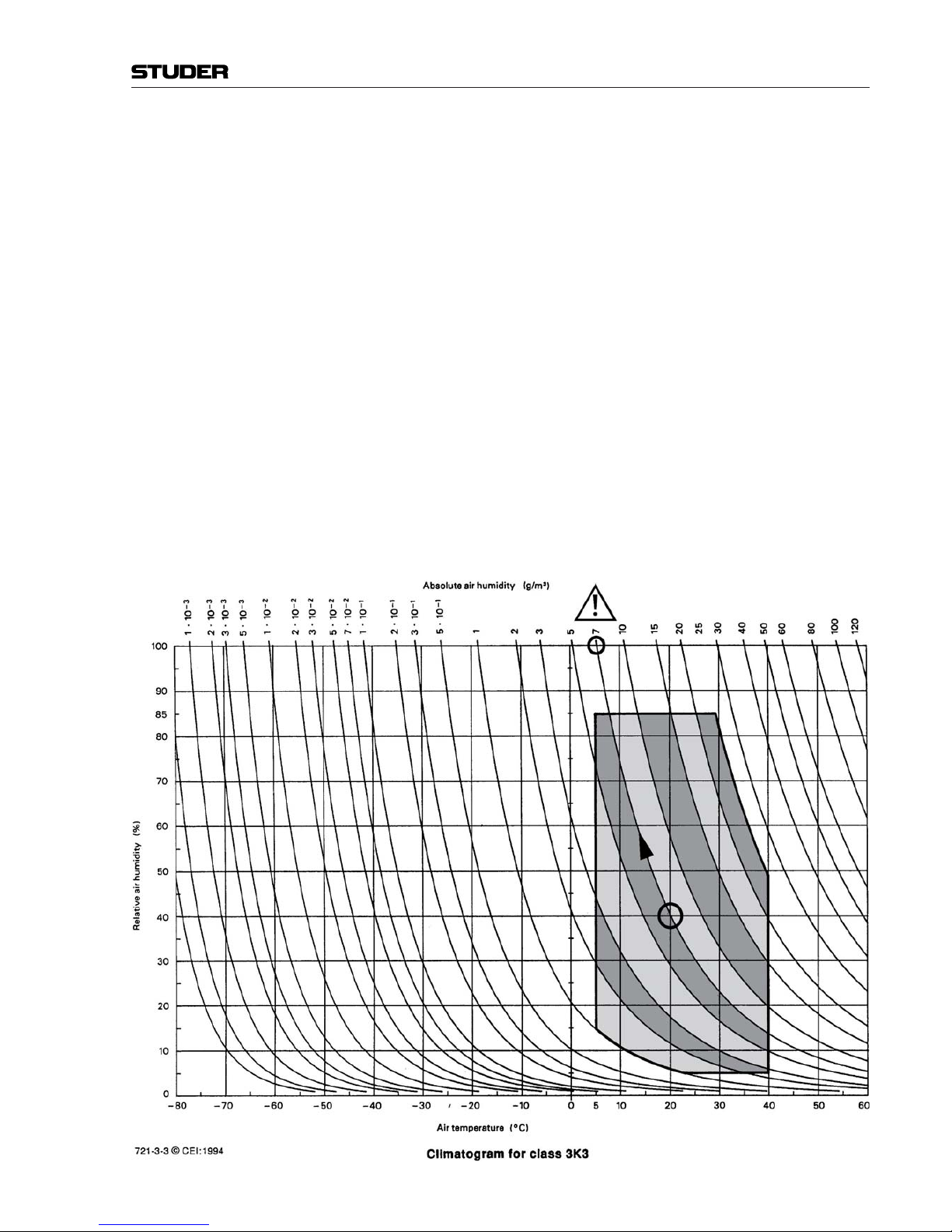
Normal operation of the unit or system is warranted under the ambient condi-
tions defined by EN 60721-3-3, set IE32, value 3K3.
This standard consists of an extensive catalogue of parameters, the most
important of which are: ambient temperature +5...+40 °C, relative humid-
ity 5...85% (i.e., no formation of condensation or ice); absolute humidity
1...25 g/m³; rate of temperature change < 0.5 °C/min. These parameters are
dealt with in the following paragraphs.
Under these conditions the unit or system starts and works without any prob-
lem. Beyond these specifications, possible problems are described below.
Ambient Temperature
Units and systems by Studer are generally designed for an ambient tempera-
ture range (i.e. temperature of the incoming air) of +5 °C to +40 °C. When
rack mounting the units, the intended air flow and herewith adequate cooling
must be provided. The following facts must be considered:
• The admissible ambient temperature range for operation of the semicon-
ductor components is 0 °C to +70 °C (commercial temperature range for
operation).
• The air flow through the installation must provide that the outgoing air is
always cooler than 70 °C.
• Average heat increase of the cooling air shall be about 20 K, allowing for
an additional maximum 10 K increase at the hot components.
• In order to dissipate 1 kW with this admissible average heat increase, an
air flow of 2.65 m³/min is required.
Example: Arack dissipating P = 800 W requires an air flow of 0.8 * 2.65 m³/minwhich
corresponds to 2.12 m³/min.
• If the cooling function of the installation must be monitored (e.g. for fan
failureor illumination withspot lamps), theoutgoing air temperaturemust
be measured directly above the modules at several places within the rack.
The trigger temperature of the sensors should be 65 °C to 70 °C.
Frost and Dew
The unsealed system parts (connector areas and semiconductor pins) allow
for a minute formation of ice or frost. However, formation of dew visible to
the naked eye will already lead to malfunctions. In practice, reliable opera-
tion can be expected in a temperature range above –15 °C, if the following
general rule is considered for putting the cold system into operation:
If the air within the system is cooled down, the relative humidity rises. If it
reaches100%, condensationwill arise,usually inthe boundarylayer between
the air and a cooler surface, together with formation of ice or dew at sensi-
tive areas of the system (contacts, IC pins, etc.). Once internal condensation
occurs,trouble-free operationcannot beguaranteed, independentof tempera-
ture.
Before putting into operation, the system must be checked for internal for-
mation of condensation or ice. Only with a minute formation of ice, direct
Appendix

IX
evaporation (sublimation) may be expected; otherwise the system must be
heated and dried while switched off.
Asystem without visible internal formation of ice or condensation should be
heatedup with itsown heat dissipation,as homogeneously(and subsequently
as slow) as possible; the ambient temperature should then always be lower
than the one of the outgoing air.
If it is absolutely necessary to operate the cold system immediately within
warm ambient air, this air must be dehydrated. In such a case, the absolute
humidity must be so low that the relative humidity, related to the coldest
system surface, always remains below 100%.
Ensurethat theenclosedair isasdry aspossible when poweringoff(i.e. before
switching off in winter, aerate the room with cold, dry air, and remove humid
objects such as clothes from the room).
These relationships are visible from the following climatogram. For a con-
trolled procedure, thermometer and hygrometer as well as a thermometer
within the system will be required.
Example 1: AnOB-van havingan internaltemperatureof 20 °Cand arelative humidityof
40% is switched off in the evening. If the temperature falls below +5 °C, the
relative humidity will rise to 100% (7 g/m³); dew or ice will be forming.
Example 2: An OB-van is heated up in the morning with air of 20 °C and a relative
humidity of 40%. On all parts being cooler than +5 °C, dew or ice will be
forming.
Appendix

X
Appendix 2: Mains Connector Strain Relief
For anchoring connectors without a mechanical lock (e.g. IEC mains connec-
tors), we recommend the following arrangement:
Procedure: The cableclamp shippedwith yourunitis auto-adhesive.For mountingplease
follow the rules below:
• The surface to be adhered to must be clean, dry, and free from grease, oil,
or other contaminants. Recommended application temperature range is
+20 °C to +40 °C.
• Remove the plastic protective backing from the rear side of the clamp
and apply it firmly to the surface at the desired position. Allow as much
time as possible for curing. The bond continues to develop for as long as
24 hours.
• For improved stability, the clamp should be fixed with a screw. For this
purpose, a self-tapping screw and an M4 bolt and nut are included.
• Placethe cable intothe clampas shown inthe illustrationabove and firmly
press down the internal top cover until the cable is fixed.
Appendix

XI
Appendix 3: Software License
Use of the software is subject to the Studer Professional Audio Software
License Agreement set forth below. Using the software indicates your accep-
tance of this license agreement. If you do not accept these license terms, you
are not authorized to use this software.
Under the condition and within the scope of the following Terms and Con-
ditions, Studer Professional Audio GmbH (hereinafter “Studer”) grants the
right to use programs developed by Studer as well as those of third parties
which have been installed by Studer on or within its products. References
to the license programs shall be references to the newest release of a license
program installed at the Customer’s site.
Programs Covered by the Agreement
License Programs of Studer The following Terms and Conditions grant the right to use all programs of
Studer that are part of the System and/or its options at the time of its delivery
to the Customer, as well as the installation software on the original data disk
and the accompanying documentation (“License Material”). In this Agree-
ment the word “Programs” shall have the meaning of programs and data
written in machine code.
Using the software indicates your acceptance of this license agreement. If
you do not accept these license terms, you are not authorized to use this soft-
ware.
Programs of Third Parties Programs of thirdparties areall programs whichconstitute part ofthe System
and/or its options at the time of delivery to the Customer but have not been
developed by Studer. The following conditions are applicable to programs of
third parties:
• The right to use third parties’programs is governed by the LicenseAgree-
mentattached hereto(if applicable),which isan integralpart ofthisAgree-
ment. The Customer shall sign any and all License Agreements for all
further programs of third parties installed on the system. The Customer
shall be deemed to have received all License Agreements upon delivery
of the system and/or its options.
• Studer shall accept no responsibility or liability for, and gives no warran-
ties (express or implied) as to the programs of third parties. The Customer
waives any and all claims versus Studer for any consequential damages,
which might occur due to defects of these programs.
Right of Use
Principle Studer grants the Customer the non-exclusive right to use the License Ma-
terial in one copy on the system and/or its options as laid down by the Sales
Agreement concluded between the parties and all Terms and Conditions
which shall be deemed to form and be read and construed as part of the
Sales Agreement. This right is assignable according to the “Assignability”
paragraph hereinafter.
Customized Configurations The Customer is not entitled to alter or develop further the License Material
except within the expressly permitted configuration possibilities given by the
software installed on the system or elsewhere. All altered programs, includ-
Appendix

XII
ing but not limited to the products altered within the permitted configuration
possibilities, are covered by this License Agreement.
Reverse Engineering Reverse engineering is only permitted with the express consent of Studer.
The consent of Studer can be obtained but is not limited to the case in which
the interface software can not be provided by Studer. In any case Studer has
to be informed immediately upon complete or partial reverse engineering.
Copying the License Material The Customer is entitled to make one copy of all or parts of the License
Material as is necessary for the use according to this Agreement, namely for
backup purposes. The Customer shall apply the copyright of Studer found on
the License Material onto all copies made by him. Records shall be kept by
theCustomer regardingthe amountof copies madeand theirplace ofkeeping.
The responsibility for the original program and all copies made lies with the
Customer. Studer is entitled to check these records on first request. Copies
not needed anymore have to be destroyed immediately.
Disclosure of License Material The License Material is a business secret of Studer. The Customer shall not
handout orinany waygive accesstoparts oforthe completeLicense Material
to third parties nor to publish any part of the License Material without prior
written consent of Studer. The Customer shall protect the License Material
andany copiesmade accordingto the paragraphabove byappropriate defense
measures against unauthorized access. This obligation of non-disclosure is a
perpetual obligation.
Third parties are entitled to have access to the License Material if they use the
License Material at the Customer’s site in compliance with this Agreement.
Under no circumstance are third parties entitled to have access to the instal-
lation software on the original data media. The Customer shall safeguard the
original data media accordingly.
Assignability The rights granted to the Customer according to this LicenseAgreement shall
only be assignable to a third party together with the transfer of the system
and/or its options and after the prior written consent of Studer.
Rights to License Material
With the exception of the right of use granted by this License Agreement all
proprietary rights to the License Material, especially the ownership and the
intellectual property rights (such as but not limited to patents and copyright)
remain with Studer even if alterations, customized changes or amendments
have been made to the License Material.
Studer’s proprietaryrights areacknowledged bythe Customer.TheCustomer
shallundertake noinfringements andmake noclaimsof anypatent, registered
design, copyright, trade mark or trade name, or other intellectual property
right.
Warranty, Disclaimer, and Liability
For all issues not covered herewithin, refer to the “General Terms and Condi-
tions of Sales and Delivery” being part of the sales contract.
Appendix

Vista 5 Digital Mixing System
Introduction 1-1
Date printed: 22.12.06 SW V3.6
CHAPTER 1
1 Introduction.........................................................................................................................................................................3
1.1 Operating Principles...................................................................................................................................................... 3
1.1.1 Vistonics®............................................................................................................................................................. 4
1.1.2 Momentary/Latching Key Activation ............................................................................................................7
1.1.3 Ganging.................................................................................................................................................................8
1.2 The Graphic Controller (GC)........................................................................................................................................9
1.2.1 GC Screen Examples .......................................................................................................................................... 10
1.3 Channels, Routing, and Buses ....................................................................................................................................13
1.4 Processing Blocks.......................................................................................................................................................14
1.5 Monitoring and Communication.................................................................................................................................14
1.6 Static Automation Functions....................................................................................................................................... 16

Vista 5 Digital Mixing System
1-2 Introduction Date printed: 22.12.06
SW V3.6

Vista 5 Digital Mixing System
Introduction 1-3
Date printed: 22.12.06 SW V3.6
1 INTRODUCTION
1.1 Operating Principles
StuderVista5incorporates operatingprinciples thatareapplicable throughout
nearly the whole console operation:
• Vistonics®
• Momentary/Latching Key Activation
• Ganging
These operating principles are described below, they are freely combinable.
Some exceptions may occur where the combination of functions is not practi-
cal. The real speed and easiness of operation will become obvious to a sound
engineer by using and combining these operating principles in every day
life.

Vista 5 Digital Mixing System
1-4 Introduction Date printed: 22.12.06
SW V3.6
1.1.1 Vistonics®
Vistonics® allows color and shape of controls to be varied according to good
ergonomicpractice.Agivenaudio functionisalways associatedwith thesame
color, and a parameter is always associated with the same icon displaying
values graphically – just as or even more intuitive than an analog console.
Vistonics® makes it possible to bring the location where you can see a value
to exactly the place where you control it. Therefore, tiring translation pro-
cesses between looking at a screen and finding the corresponding hardware
control somewhere else are not existing anymore, saving just a little time and
energy a few hundred times a day!
Great attention has been paid in order to make the current association clearly
visible. Color coding has been used to indicate families of audio functions
such as EQ, dynamics, etc. Consistent icons make the physical meaning of
an audio function obvious – e.g. bar graph-like icons indicate levels, time
adjustments are indicated by clock dials, etc. This way, it is easy to identify
the currently associated function even from a distance.
The Vistonics® module consists of two main parts: 40 rotary controls with
push buttons next to each of them, as well as a touch screen area, showing
graphically the most important settings of each channel: Dynamics, EQ and
panninginformation. Itispossible tochange theassociationof arotary control
to audio functions either globally or locally:
View = Control Location View = Control Location
Display
+ Controls
Conventional TFT Approach Vistonics Technology
Controls
Display
/

Vista 5 Digital Mixing System
Introduction 1-5
Date printed: 22.12.06 SW V3.6
Global Views Up to four different parameters are shown in each channel strip. The same
four parameters will be shown globally on the whole console. This mode is
meant to be the “horizontal way of operation”, mostly used for e.g. operat-
ing auxiliaries or input settings. The picture below shows a globalAUX 1...4
view.
The touch screen area is also used for indication and operation of bus assign-
ment:
Bus Assign Overview:

Vista 5 Digital Mixing System
1-6 Introduction Date printed: 22.12.06
SW V3.6
Local Views By touching the graphics shown below the Vistonics® rotary controls, the
whole parameter set of that specific curve is displayed, also covering some
of the neighboring channel strips. It is also possible to touch any two curves
in one bay in order to display both at the same time.
The example below shows the complete dynamics section of the leftmost
channel (the small dynamics view is highlighted), overlaid to a global AUX
view.
This philosophy is completed by three hardware keys underneath the Viston-
ics®display, showingdifferentcombinations ofparameters aswell asthe bus
assignment of that specific channel, covering the whole Vistonics® area.
Bus Assign View: (here, channels can directly be assigned to a bus)
Other manuals for Vista 5 M2
1
Table of contents
Other Studer Music Mixer manuals

Studer
Studer OnAir 500 Modulo Quick guide

Studer
Studer Compact InfinityCore 300 User manual

Studer
Studer D19m Operating instructions

Studer
Studer OnAir 3000 User manual

Studer
Studer OnAir 2500 User manual

Studer
Studer SW V4.0 OnAir 1000 Training manual

Studer
Studer Vista 5 M2 User manual

Studer
Studer Vista 1 User manual

Studer
Studer 928 Operation manual

Studer
Studer D950 User manual