Studio Electronics MODSTAR User manual

!
!
!
!
!
!
!
!
!
!
!
!
!
!
BOOMSTAR MODULAR SYNTHESIZER SYSTEM
MODSTAR
RESONANT FILTER and AMP OPERATION MANUAL
!
!
!
!
!
AMP
407550893003
DRIVE
ST 1/2
OUTPUTST 2/2ST 2/1
ST 1/1INPUT
INPUT
OUTPUT
STAGE 2/2
STAGE 1/2
DRONE
FULL
INPUT
1 V/O FREQ CV 1 FREQ CV 2 RESO CV
OUTPUT OUTPUT
FREQUENCY
FREQ CV 1
INPUT OUTPUT
FREQ CV 2
RESO CV
RESONANCE
HALF
TRACK
FULL
INPUT
1 V/O FREQ CV 1 FREQ CV 2 RESO CV
OUTPUT OUTPUT
FREQUENCY
FREQ CV 1
INPUT OUTPUT
FREQ CV 2
RESO CV
RESONANCE
HALF
TRACK
INPUT
1 V/O FREQ CV 1 FREQ CV 2 RESO CV
OUTPUT OUTPUT
FREQUENCY
FREQ CV 1
INPUT OUTPUT
FREQ CV 2
RESO CV
RESONANCE
HALF
TRACK

IMPORTANT INSTRUCTIONS - PLEASE READ
!
!
!
Please read the Boomstar Modular Synthesizer Manual completely before use, and retain for future reference.
!
IMPORTANT Ribbon Cable Power Information:
Boomstar Modular combines a set of individual modules to create a complete instrument. The individual modules can be
rearranged, removed, and replaced with any compatible eurorack modules from Studio Electronics and other manufacturers.
!
Boomstar Modular uses a standard eurorack power rail to connect the modules to the internal bipolar +/-12v power supply. Please pay very close attention to
the orientation of the ribbon cable when adding and removing modules. The stripe on the ribbon cable marks -12v. This stripe needs to line up with the -12v
pins on the power rail and the -12v pins on the module. Failure to match up the pins correctly can result in damage to one or all the modules in the
Boomstar Modular. On the power rail, the -12v pins are clearly labeled. On the individual modules, the positive and negative sides of the pin connectors are
labeled next to the power header on either the top or bottom of the PCB.
!
Do NOT remove individual modules from the Boomstar while synthesizer is plugged in.
!
NEVER unplug ribbon cables from the Boomstar Modular, or any other modules while the Boomstar Modular is plugged in.
!
!
!
i

Table of Contents
!
!
!
Box Contents ..………………………….……….………………………………….…… 1
Dimensions & Power Specifications ……………………………………………… 2-3
Boomstar Modular Introduction ………………………………………….………… 4
Modular Signal Paths ………………………….……………………………….…….. 5
Complete MODSTAR Systems ………………..….……………………………..….. 6-8
Individual Modules …………….……………….……………………………………… 9-24
1 Year Limited Warranty ……………………………………………………….…….. 25-26
Support & Contact ……………………………………………………………………… 27!
ii

Box Contents
!
!
Module(s) of choice
1x Ribbon Cable
1x Information Card!
1

DIMENSIONS & POWER SPECIFICATIONS
!
Filters
5089 –!Size: 12hp
Module depth with ribbon cable attached: 39.7mm
+12 / -12 Power Usage: 40mA, 28mA
!
4075 –!Size: 12hp
Module depth with ribbon cable attached: 39.7mm
+12 / -12 Power Usage: 23mA, 30mA
!
3003 – Size: 12hp
Module depth with ribbon cable attached: 39.7mm
+12 / -12 Power Usage: 37mA, 25mA
!
SEM – Size: 12hp
Module depth with ribbon cable attached: 39.7mm
P +12 / -12 Power Usage: 23mA, 23mA
!
!
!
2

DIMENSIONS & POWER SPECIFICATIONS - 2
Amplifier
AMP – Size: 8hp
Module depth with ribbon cable attached: 39.7mm
+12 / -12 Power Usage: 36mA, 12mA
!
Analog Oscillator
OSCILLATION –!Size: 48hp
Module depth with ribbon cable attached: 39.7mm
Power Usage:
!
Digital Oscillator
GRAINY CLAMP-IT –!Size: 19hp
Module depth with ribbon cable attached: 35mm
Power Usage: 50mA max
!
3

Boomstar Modular Introduction
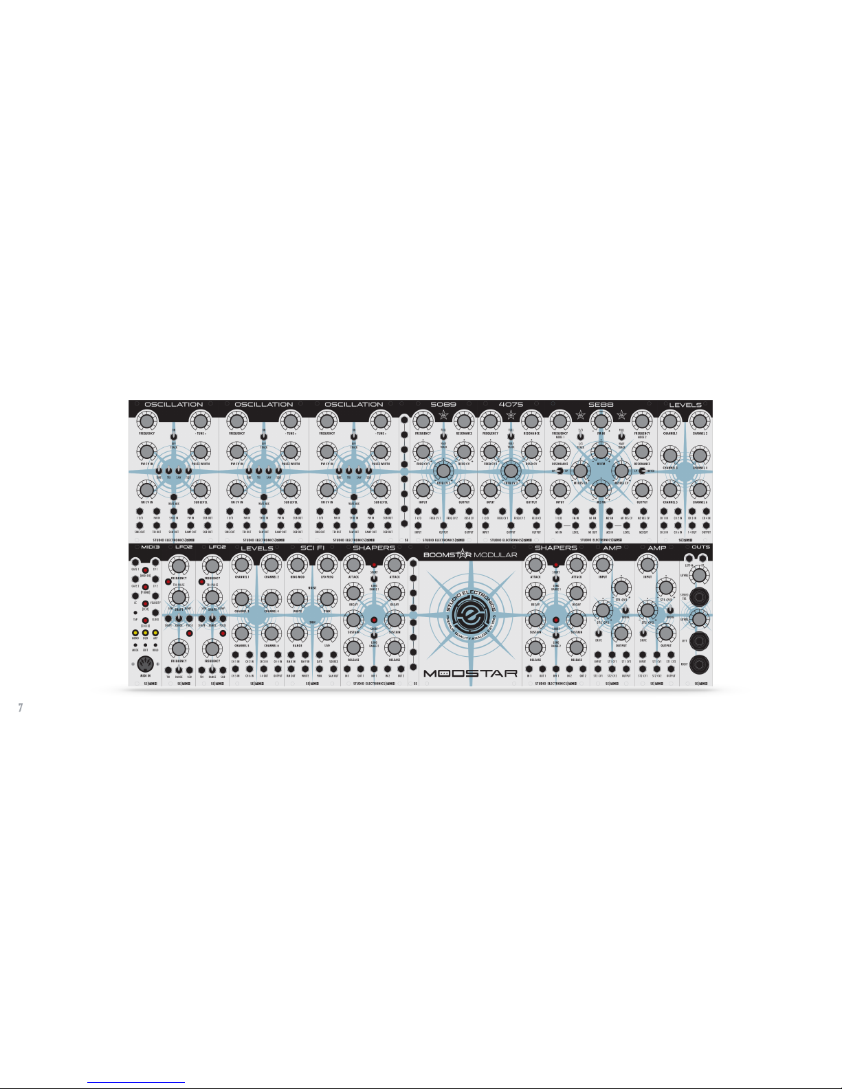
THE BOOMSTAR MODULAR SYSTEM realizes the seemingly inevitable!eurorack sprawl of our semi-modular BOOMSTAR
desktop synth, consisting of 14 modules that dramatically open up the root level programming and sound sculpting of that
lush, potent, and fantastically flexible multi-filtered Boomstar sound.
!
What makes it tick: Let’s tick ‘em off: Class A 5089, 3003 and AMP *, rugged through-hole construction, discrete circuitry,
hand-matched transistors in the filters and amplifier, multi-filtered, hand-crafted, Premium Quality Analog sound. We’d like to
think we’ve learned a few things bringing the MIDIMINI, SE1-X, ATC-X, polyphonic CODE OMEGA synths, MODMAX PEDALS,
C2S, PRE 2, and SLATE PRO AUDIO DRAGON and FOX to market, and the air waves worldwide.
!
Our Boomstar Modular System’s (Modstar) 5089 circuit mirrors faithfully the filter design from the Minimoog—it is not a style;
it’s not a type, not reminiscent of, not vintage inspired—it is the analog sound standard manufactured anew, and how we love it
so. Apply the same thinking to our 4075, 3003, and SE80 filters vis-à-vis their originals, and you’ve caught our drift; the
OSCILLATION and AMP modules also resonate with the Mini’s timeless designs, functionality, and gorgeous, gleaming sound—
modernized and reimagined by the maestro Tim Caswell himself, but we’re just getting started here; the SEM filter is on deck.
!
We hope you are as thrilled with your purchase of the complete system/individual modules as we are with our partnership with
PITTSBURGH MODULAR, and the final highly collaborative through-hole designs which flowed from the first Nicol/St. Regis
Beer Summit at Winter NAMM ’13. The MODSTAR module breakdown upshot: Filters, Oscillators, and AMP are built by SE,
and the intoxicating remainder by our good friends and exceedingly savvy business partners at PGH—without whose
invaluable, real world/walking the streets of Euroland insights, experience, and deep resources, this project would have faded
to grey. A tip of the SE chapeau to Richard Nicol, Perry, and the full-strength, generally less-weathered outfit at P. M. AND to
Geoff Farr who relentlessly hounded the St. Regis bros—“When are the euro modules going to be ready?” Looks.
*See pg.17, par. 2 for caveat.!
4

Modular Signal Paths
(Copy courtesy of Pittsburgh Modular)
!
The BOOMSTAR MODULAR’S signal path is divided into two types of signals: audio signals and control
voltages.
!
The audio signal is the sound that is produced. The audio signal path starts at a sound source such as a
Waveforms oscillator, LFO running at audio rate, or the Filter in oscillator mode. The audio signal is then
patched through other modules used to shape the sound such as mixers, filters, and amplifiers.
!
Control voltages (CV) manipulate the audio signal in several different ways.
!
Gates are represented by a high or low control voltage. A gate can be generated using a square or pulse
wave from an oscillator or LFO, or by using a gate output from an external sequencer, or MIDI keyboard.
A gate can be shaped using an envelope generator to control the attack, decay, sustain, and release of
the gate. The modified gate signal can then be sent to any CV input on the synth.
!
A second use for control voltages is as a modulation source. For example, a control voltage from the
SCI-FI S/H OUT (Sample and Hold) module patched into the 1V/O input on an OSCILLATION module
controls the frequency of the oscillator based on the randomly generated sequence of notes,
additionally, the OSCILLATION module’s full range oscillators make perfect control voltage modulation
sources; and audio signals make excellent control voltage source for oscillator FM (frequency
modulation). Understanding exactly how it works can sometimes hinder creativity—experiment!
!
5

Boomstar Modular MODSTAR SEITO
MODSTAR SEITO 104 hp: MIDI 3 6hp, OSCILLATION (x2) 32hp, 4075 12hp, MULTIPLE 2hp, LEVELS 10hp, SCI-FI 10hp, SHAPERS 12hp, AMP 8hp, LFO2 6hp, OUTS
6hp. Hugged-up nicely in Pittsburgh Modular’s Move 104 Mobile Eurorack Modular Case, to safely house and power it up. Hand-built in Pittsburgh using select
Ukrainian Birch Ply, it celebrates the classic pairing of synthesizers with beautiful hardwood—constructed and stained by seasoned craftsmen to emphasize its
unique beauty. Each Move case includes a removable lid; when attached, the lid fits over the patch cables allowing your fully patched modular to hit the road.!
6

Boomstar Modular MODSTAR SENSEI
!
7

Boomstar Modular MODSTAR SENSEI - 2
!
MODSTAR SENSEI 178 hp: OSCILLATION (x3) 48hp, MULTIPLE 2hp, 5089 12hp, 4075 12hp, SE88 20hp, LEVELS 10hp, MIDI 3 6hp, LFO2 6hp, LFO B 6hp (LFO2
pictured), LEVELS 10hp, SCI-FI 10hp, SHAPERS 12hp, MULTIPLE 2hp, MODSTAR BEAUTY PLATE 18hp, SHAPERS 12hp, AMP (x2) 16hp, 6hp, OUTS 6hp. Double
hugged in Pittsburgh Modular’s Move 208 Mobile Eurorack Modular Case.*
!
*Sensei specs. subject to change.
!
MODELS NOW SHIPPING DETAILED BELOW.!
8

5089 Filter Module
Description
The 5089 filter is a voltage controlled, discrete analog, 24 db/oct transistor ladder, low-pass filter, employing hand-matched
transistors. Our ladder low-pass filter—a subtractive analog sound synthesis foundation—in its lowest FREQUENCY setting
removes, or cuts off higher frequency harmonics; its RESONANCE or Q circuit emphasizes those harmonics to the point of
“squealy,” giddy self-oscillation, tracking the keyboard in its FULL setting quite nicely if seeking an alternative sine wave.
!
Our 5089 has the roundest, slickest tone of all the Boomstar’s filters. Go easy on it, and round, creamy buttery flavors wrap
the oscillators in earthy warmth; smash it and a!meaty, satisfying overdrive, and a maximum harvest of vintage 1960s and
1970s organic-sounding, second-order harmonic distortion fill the plate. Every setting is balanced and bountiful. Looking for
traditional R ’n B baselines and leads? Focus here on the rich saturation of this benchmark filter and its symmetrical cascades
of generation-stretching timbres. All BOOMSTAR MODULAR filters are hand-built in the U. S. Pick-and-Place all the way!
!
Potentiometer Potential
Three attenuverter and four attenuation pots control the FREQUENCY, RESONANCE, FREQ CV 1, RESO CV, FREQ CV 2, INPUT
and OUTPUT, delivering smooth, detailed, and complex expression.
!
Switch It Up
!
Classic Minimoog FULL and HALF strength filter frequency keyboard/voltage tracking for rounder low end with brilliant highs.
!
Patch It Up
Seven patch points: 1 V/O, FREQ CV 1, FREQ CV 2, RESO CV, INPUT and 2x OUTPUT direct the deepest manipulation.!
9

5089 Filter Module - 2
All Controls and Patch Points
FREQUENCY –!Adjusts the frequency, or cut-off of the filter.
RESONANCE –!Adjusts the resonance, or “Q” of the filter. *
FULL HALF TRACK –!Switch between full and half keyboard/voltage tracking.
FREQ CV 1 –!Frequency control voltage 1 input attenuverter.
RESO CV – Resonance control voltage input attenuverter.
FREQ CV 2 – Frequency control voltage 2 input attenuverter.
INPUT – Adjusts the audio input.
OUTPUT – Adjusts the audio output.
1 V/O – One volt per octave control voltage input.
FREQ CV 1 – Frequency control voltage 1 input.
FREQ CV 2 – Frequency control voltage 2 input—get tricky with the second attempt.
RESO CV – Resonance control voltage input—use for shimmers or howling wolf tones.
INPUT – Audio input.
2x OUTPUT – Audio outputs.
!
*From 7:00 (0) to 9:00 our “Negative Resonance Saturation” adds beefiness, boosting the waveform amplitude and taming
waveform transients; set to 9:00 to achieve the cleanest tone possible.!
10

4075 Filter Module
Description
The 4075 filter is a voltage controlled, discrete analog, 24/db/oct cascaded transconductance low-pass filter, employing hand-
matched transistors. In its lowest FREQUENCY setting it shaves off higher frequency harmonics; its RESONANCE or “Q”
circuit pushes those harmonics past the self-oscillation boiling point, projecting a thumpy, thrashing squeal, with explosive low
to mid-range power and depth. The design is actually pulled from the four-pole ARP 4072 (better: more parts and trims), sans
the 12kHz design flaw which hamstrung the original’s high end. The 4075 name has stuck—no correcting our little misnomer.
!
Our 4075 filter is the most requested of the Boomstar filter models, perhaps owing to its uniqueness. Has there ever been a
better match for a square wave? It weaves dreams with “glidey,” 70s basslines, is a natural in the lead department, and feels
as if a temper tantrum simmers a mere micron beneath its veneer of faux respectability. Aggressive and articulate, this fresh
ARP can snap punishing kick drum sounds out as well as color with bright, edgy, stringy tones for essential arpeggiations.
!
Potentiometer Potential
Three attenuverter and four attenuation pots control the FREQUENCY, RESONANCE, FREQ CV 1, RESO CV, FREQ CV 2, INPUT
and OUTPUT, delivering smooth, detailed, and complex expression.
!
Switch It Up
!
Classic Minimoog FULL and HALF strength filter frequency keyboard/voltage tracking for rounder low end with brilliant highs.
!
Patch It Up
Seven patch points: 1 V/O, FREQ CV 1, FREQ CV 2, RESO CV, INPUT and 2x OUTPUT direct the deepest manipulation.!
11

4075 Filter Module - 2
All Controls and Patch Points
FREQUENCY –!Adjusts the frequency, or cut-off of the filter.
RESONANCE –!Adjusts the resonance, or “Q” of the filter. *
FULL HALF TRACK –!Switch between full and half keyboard/voltage tracking.
FREQ CV 1 –!Frequency control voltage 1 input attenuverter.
RESO CV – Resonance control voltage input attenuverter.
FREQ CV 2 – Frequency control voltage 2 input attenuverter.
INPUT – Adjusts the audio input.
OUTPUT – Adjusts the audio output.
1 V/O – One volt per octave control voltage input.
FREQ CV 1 – Frequency control voltage 1 input.
FREQ CV 2 – Frequency control voltage 2 input—get tricky with the second attempt.
RESO CV – Resonance control voltage input—use for shimmers or howling wolf tones.
INPUT – Audio input.
2x OUTPUT – Audio outputs.
!
*From 7:00 (0) to 9:00 our “Negative Resonance Saturation” adds beefiness, boosting the waveform amplitude and taming
waveform transients; set to 9:00 to achieve the cleanest tone possible.!
12

3003 Filter Module
Description
The 3003 filter is a voltage controlled, discrete analog 18 db/oct ladder low-pass filter, employing hand-matched transistors.
Drop the FREQUENCY knob to 0 and things get pretty dull; swing it back up and those "Transistor Bass” highs come crashing
through the gate. The 3003’s RESONANCE circuit at max will sing out more than the TB’s signature chirping in a fun, bubbly,
if washy, poorer relation, Mini “clone-ish" way; use it tastefully, or throw moderation to the wind for overwhelming chirp force.
!
Our 3003 filter has the most gentle sonic touch of its partners in the Boomstar fold, but nevertheless is quite capable of
shaping precise, very dynamic tone. Whether or not this STUDIO ELECTRONICS filter is filling its traditional baseline boxing
niche, driving a harsh, liquid, acid-like tone, a softer more rubber-bandy SH-101-ish presence, or out of the bass range
altogether, leading the way, all is within easy reach of this surprisingly warm and versatile VCF. The 3003 can be distinctly
vocal at times, especially when one is willing to put grittier, more distorted desires aside.
!
Potentiometer Potential
Three attenuverter and four attenuation pots control the FREQUENCY, RESONANCE, FREQ CV 1, RESO CV, FREQ CV 2,
INPUT and OUTPUT, delivering smooth, detailed, and complex expression.
!
Switch It Up
!
Classic Minimoog FULL and HALF strength filter frequency keyboard/voltage tracking for rounder low end with brilliant highs.
!
Patch It Up
Seven patch points: 1 V/O, FREQ CV 1, FREQ CV 2, RESO CV, INPUT and 2x OUTPUT direct the deepest manipulation.!
13

3003 Filter Module - 2
All Controls and Patch Points
FREQUENCY –!Adjusts the frequency, or cut-off of the filter.
RESONANCE –!Adjusts the resonance of the filter. *
FULL HALF TRACK –!Switch between full and half keyboard/voltage tracking.
FREQ CV 1 –!Frequency control voltage 1 input attenuverter.
RESO CV – Resonance control voltage input attenuverter.
FREQ CV 2 – Frequency control voltage 2 input attenuverter.
INPUT – Adjusts the audio input.
OUTPUT – Adjusts the audio output.
1 V/O – One volt per octave control voltage input.
FREQ CV 1 – Frequency control voltage 1 input.
FREQ CV 2 – Frequency control voltage 2 input—get tricky with the second attempt.
RESO CV – Resonance control voltage input—use for shimmers or howling wolf tones.
INPUT – Audio input.
2x OUTPUT – Audio outputs.
!
*From 7:00 (0) to 9:00 our “Negative Resonance Saturation” adds beefiness, boosting the waveform amplitude and taming
waveform transients; set to 9:00 to achieve the cleanest tone possible. !
14

SEM Filter Module
Description
Sensei Caswell: "Our SEM is known as a "Voltage Controlled State Variable Filter" because it provides simultaneous high pass,
low pass, and band pass outputs, all with a 12 dB/oct slope. The notch is the inverse of the bandpass, achieved by summing
the Low Pass and high pass outputs. This version is a combination of the original SEM filter and the newer design from the
OBX, along with improvements by SE. It has a modest current draw, evenly from the plus and minus rails."
!
If you've heard the SEM filter in our Boomstar desktop (https://soundcloud.com/studio-electronics/sets/mean-sem-ranch/)
you also know that this 12 dB favorite is “… capable of lighter, more subtle tones than the other three models. This isn't to
suggest the filter's Low Pass mode can't cater for fat and punchy, because it can." - Paul Nagle, Sound on Sound. Deeply
gratifying tonal variance and this emotional warmth https://soundcloud.com/alanc3-1/switched-on-sem—our friend Fred
Falke's favorite—can reach into your head and heart, and stay as long as desired. Thank you Lord Tom Oberheim for this
marvelous design/template from which we were able to work our very own Studio Electronics eurorack filter enchantments.
!
Potentiometer Potential
Three attenuverter and four attenuation pots control the FREQUENCY, RESONANCE, FREQ CV 1, RESO CV, LP HP, INPUT
and OUTPUT, delivering smooth, detailed, and ever variable expression.
!
Switch It Up
!
FULL and HALF strength filter frequency keyboard/voltage tracking, and BP / LP-HP modes.
!
Patch It Up
Seven patch points: 1 V/O, FREQ CV 1, FREQ CV 2, RESO CV, INPUT, BP LP-HP, and OUTPUT jack you in.!
15

SEM Filter Module - 2
All Controls and Patch Points
FREQUENCY –!Adjusts the frequency, or cut-off of the filter.
RESONANCE –!Adjusts the resonance of the filter. *
FULL HALF TRACK –!Switch between full and half keyboard/voltage tracking.
FREQ CV 1 –!Frequency control voltage 1 input attenuverter.
RESO CV – Resonance control voltage input attenuverter.
FREQ CV 2 – Frequency control voltage 2 input attenuverter.
INPUT – Adjusts the audio input.
OUTPUT – Adjusts the audio output.
1 V/O – One volt per octave control voltage input.
FREQ CV 1 – Frequency control voltage 1 input.
BP OUT – Band Pass Output. No cable patched, BP passes through the mains.
RESO CV – Resonance control voltage input—use for shimmers or howling wolf tones.
LP HP – Low Pass / High Pass attenuverter.
INPUT – Audio input.
OUTPUT – Audio output.
!
*From 7:00 (0) to 9:00 our “Negative Resonance Saturation” adds beefiness, boosting the waveform amplitude and taming
waveform transients; set to 9:00 to achieve the cleanest tone possible.!
16

AMP Module
Description
From Designer Tim Caswell’s own hand: The amplifier (AMP) is a 2 stage Class A discrete design using three pairs of hand matched
transistors. Envelope is usually applied to ST1 CV1; ST1 CV2 goes thru an attenuverter and can be used for envelope or modulation;
ST2 CV1 goes to the 2nd stage, and is typically used for volume control; ST2 CV2 goes thru an attenuverter providing access to the final
stage of modulation input.
!
The AMP, the 5089, and the 3003 are Class A circuits. They draw more current from the +12 rail than from the -12 volt rail. If the
system power supply is under-sized, hum or buzz may be heard. In that case, larger filter capacitors and/or a larger power transformer
will be needed. The 4075 draws equally from both rails, and is more immune to hum. Like our time-perfected filters, this Boomstar
Modular AMP module, a gorgeous all-in-one discrete VCA charmer, is hand-built entirely in the U. S. of A—just ask Rachael Herbison!
!
Potentiometer Potential
Two attenuverter, and two attenuation pots control the INPUT, ST1 CV2 (CV), ST2 CV2 (CV), and OUTPUT.
!
Switch It Up
Uber-useful continuous hypnotic DRONE for endless sustain/release, and DRIVE—the overdrive circuit from the Boomstar desktop—for
last stage push, clipping, good ol' dirty vintage fuzz fun, and tone-crushed distortion.
!
Patch It Up
Six patch points: INPUT, ST1 CV1, ST1 CV2, ST2 CV1, ST2 CV2, OUTPUT direct the deepest manipulation. !
17
Table of contents