Studio Electronics BOOMSTAR User manual


Studio Electronics Boomstar Manual LimitedWarranty
LIMITED WARRANTY TERMS AND CONDITIONS
This Limited Warranty applies only to ANALOGIA INC./STUDIO ELECTRONICS purchased in the United States
of America. Outside the USA, warranty policy and service is determined by the laws of the country of purchase
and followed by our local authorized distributor. A listing of our authorized distributors is available at http://www.
studioelectronics.com/shop/distributors/
ANALOGIA INC./STUDIO ELECTRONICS warrants to the rst owner of a covered product purchased directly
from ANALOGIA INC./STUDIO ELECTRONICS, or an authorized ANALOGIA INC./STUDIO ELECTRONICS
dealer in the U.S., that this product will be free from defects in materials and or workmanship for a period of
one year from the date of purchase. Please register this product online at http://studioelectronics.com/support/
registration/ to establish the date of purchase (NOT A REQUIREMENT FOR WARRANTY SERVICE
BUT A
GOOD IDEA).
To exercise your rights under this Warranty as the rst owner/purchaser, YOU MUST SHIP THIS PRODUCT
IN ITS ORIGINAL PACKAGING (which we can replace and send to you for $10) at your expense, with
proof of purchase documentation and the ANALOGIA INC./STUDIO ELECTRONICS supplied power
adapter, to ANALOGIA INC. An RMA (Return Material Authorization) number from ANALOGIA INC./
STUDIO ELECTRONICS must be obtained rst before returning any product. Email RMA requests to rma@
studioelectronics.com, or call us at (310) 640-3546 to secure an RMA #. Products shipped to ANALOGIA INC.
without an RMA will be refused and returned. Shipping insurance is optional, but highly recommended.
ANALOGIA INC./STUDIO ELECTRONICS will repair or replace this product at its sole option and at no charge
to you for parts and labor—when deemed necessary and within the warranty period—provided that ANALOGIA
INC./STUDIO ELECTRONICS reserves the right to determine whether the product is “defective” for purposes
of this Limited Warranty. This Warranty does not apply if damage to this product occurrs as a result of abuse or
misuse, abnormal use or handling, improper packaging, another product’s interaction, exposure to temperature
extremes, or if the product has been altered or modied/customized in any way, or the damage was caused by
unauthorized repair or service. The original product must return to ANALOGIA INC. unaltered.
IN NO EVENT SHALL ANALOGIA INC./STUDIO ELECTRONICS BE LIABLE FOR ANY INDIRECT,
INCIDENTAL, COLLATERAL, EXEMPLARY, PUNITIVE, CONSEQUENTIAL OR SPECIAL DAMAGES OR
LOSSES ARISING OUT OF YOUR PURCHASE OF PRODUCTS AND/OR OUT OF THIS WARRANTY,
INCLUDING WITHOUT LIMITATION, LOSS OF USE, PROFITS, GOODWILL OR SAVINGS OR LOSS OF
DATA, MUSIC, ELECTRONIC FILES, OR PREFERENCES THAT MAY HAVE BEEN STORED BY A USER
OF THE PRODUCT, EVEN IF ANALOGIA INC./ STUDIO ELECTRONICS HAS BEEN ADVISED OF THE
POSSIBILITY OF SUCH DAMAGES OR CLAIMS. SOME STATES DO NOT ALLOW THE EXCLUSION OR
LIMITATION OF INCIDENTAL, PUNITIVE, OR CONSEQUENTIAL DAMAGES, SO THE ABOVE LIMITATION
OR EXCLUSION MAY NOT APPLY TO YOU.
This Limited Warranty and the right of replacement is in lieu of any and all other warranties
—
which you hereby
waive
—
and it gives U.S. purchasers specic legal rights
. Y
ou may also have other rights which vary from State
to State.
ANALOGIA INC., 530 West Palm Ave. El Segundo, CA 90245

Studio Electronics Boomstar Manual Creditsii
CIRCUIT AND SOFTWARE DESIGN
Tim Caswell
USER INTERFACE AND FEATURE SPECIALIST
Greg St. Regis
SOUND PROGRAMMING AND DEMOS
Drew Neumann Greg St. Regis Marc St. Regis
GRAPHIC DESIGN
John Greczula
PRIMARY ANALOG CONSULTANT
Drew Neumann
LEAD VENDOR LIAISON
Daniel Wendell
QUICK START GUIDE MANUAL
Marc St. Regis Greg St. Regis Camille St. Regis Daniel Wendell
VERY SPECIAL THANKS
Mary St. Regis Geoff Farr Rachael Herbison Lucy Bauer
Rev. 2.0, 5.3.2014
Information contained in this Boomstar Manual is subject to change without notice and does not represent a commitment on behalf of ANALOGIA
INC. No portion of this manual may be produced or transmitted in any form, or by any means—whether electronic or mechanical, or for any purpose
other than purchaser’s personal use—without the explicit written permission of ANALOGIA INC. All other products, logos or company names
mentioned herein are trademarks or registered trademarks of their respective owners.
© ANALOGIA INC. 2014. All Rights Reserved.
A N A L O G I A I N C.
530 West Palm Ave., El Segundo California 90245
Tel: (310) 640-3546 Web: studioelectronics.com Email: @sbcglobal.net
facebook.com/StudioElectronics • twitter.com/SE_BoomStar • youtube.com/user/StudioElectronics
soundcloud.com/studio-electronics

Studio Electronics Boomstar Manual Table of Contentsiii
1) The Design Behind the ‘Stars . . . . . . . . . . 1
2) Setup Essentials ..................... 2-6
2.1 Warnings, Precautions and Advice . ... . ... ... 2-4
2.2 Product Registration ............................. 4
2.3 Smart and Safe Connections . ... . ... .... ... . ... . 5
2.4 Boomstar Warming and Output Warning .... . 6
3) SignalFlowChart ....................... 7
3.1 A TimCaswellOriginal............................ 7
4) PatchReset.............................. 8
4.1 Sawtooth Bass Patch - Factory Reset .. ... . ... .. 8
5) Panels ................................ 9-21
5.1 Front Panel ..................................... 9-10
5.1.1 Adjustment Holes .......................... 9-10
5.1.1.1 CV input tracking adjust. .. .... .... .... . 9
5.1.1.2 Oscillator 1 high tune adjust.. .... .... .. 9
5.1.1.3 Oscillator 1 octave adjust .............. 9
5.1.1.4 Oscillator 1 initial tune adjust .. .... ... 9
5.1.1.5 Oscillator 1 scale adjust ................ 9
5.1.1.6 Oscillator 2 scale adjust .. . ... . ... . ... . . 9
5.1.1.7 Oscillator 2 initial tune adjust .. .... ... 9
5.1.1.8 Oscillator 2 high tune adjust ... ... . .. 10
5.1.1.9 Oscillator 2 octave adjust .. .... .... ... 10
5.1.1.10 Envelope Drive ....................... 10
5.1.1.11VCAOset............................. 10
5.1.1.12 VCA DC Balance ...................... 10
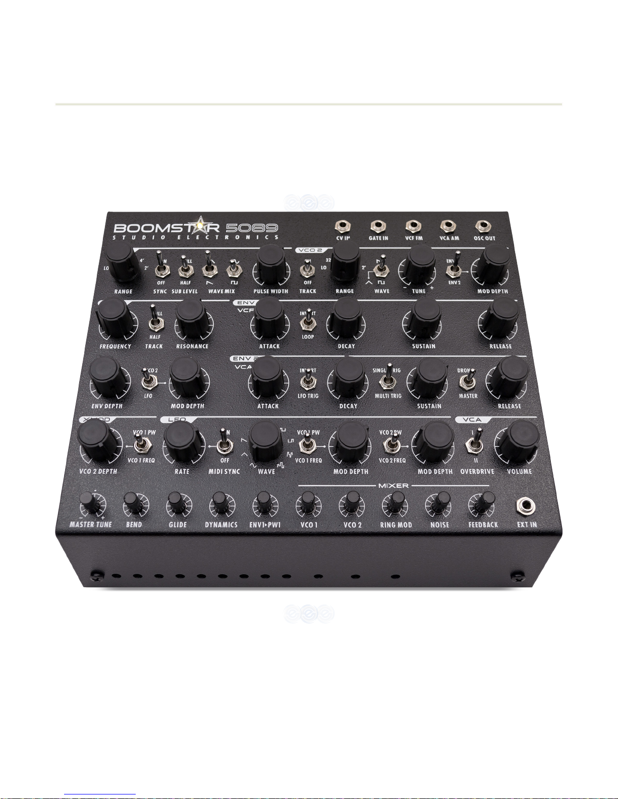
5.2 Top Panel ..................................... 11-19
5.2.1 SEM Controls .................................. 11
5.2.2 SE80 and 700 Controls ....................... 11
5.2.3 Patch Points ............................... 11-12
5.2.3.1 CV IN - Control Voltage In ............. 11
5.2.3.2 GATE IN - Gate Input .................. 11
5.2.3.3 VCF FM - VCF Frequency Mod In . . ... 11
5.2.3.4 VCA AM - VCA Amplitude Mod In . ... 11
5.2.3.5 OSC Out - Oscillator Output .......... 11
5.2.3.6 EXT IN - External Input ................ 12
5.2.4 VCO 1 - Voltage Controlled OSC 1 ......... 13
5.2.5 VCO 1 - Voltage Controlled OSC 2 ......... 14
5.2.6 VCF - Voltage Controlled Filter .......... 14-15
5.2.7 ENV 1 - Envelope 1 ........................ 15-16
5.2.8 ENV 2 - Envelope 2 ........................... 16
5.2.9 X MOD - Cross Modulation .................. 17
5.2.10 LFO - Low Frequency Oscillator ....... 17-18
5.2.11VCA-VoltageControlledAmplier ....... 18
5.2.12 Master Tune .................................. 18
5.2.13 Bend ........................................... 18
5.2.14 Glide ........................................... 18
5.2.15 Dynamics ..................................... 19
5.2.16ENV1•PW1-Envelope1toPulseWdth 19
5.2.17 MIXER ..........................................
19
5.2.17.1 VCO 1 - Voltage Cont. OSC ......... 19
5.2.17.2 VCO 2 - Voltage Cont. OSC 2 ....... 19
5.2.17.3 Ring Mod - Ring Modulation ........ 19
5.2.17.4 Noise .................................. 19
5.2.17.5 Feedback ............................. 19
5.3 Back Panel .................................... 20-21
5.3.1Connections,Switches,Warnings ..... 20-21
5.3.1.1 Audio Out ............................... 20
5.3.1.2 MIDI ..................................... 20
5.3.1.3 Power Adapter Connection .. .. ... . .. 20
5.4 Side Panel ........................................ 21
5.4.1 Rack Mounting Holes ........................ 21
6) Legal ................................ 22-23
6.1 Liability ........................................... 22
6.2 FCC ............................................. 22-23
6.2 Canada ............................................ 23
6.4 Europe ............................................ 23
7) Glossary................................ 24
8) FilterTalkers........................... 25
8.1 Bace ............................................... 25
8.2 Drew Neumann .................................. 25
9) The Ancient Chinese . . . . . . . . . . . . . . . . . . 26
10) Back PanelArt........................ 27
11) Troubleshooting ...................... 28
12) BlankPatchSheet1.................. 29
13) BlankPatchSheet2 .................. 30
BOOMSTAR OPERATION MANUAL

Studio Electronics Boomstar Manual 1Design Behind the‘Stars
1THE DESIGN BEHIND THE ‘STARS
As SEfansknow,we’vebeendoingthemultiplelterthingforsometime,andwhileourapproachhasneverbeen
one of exact emulation of the original synthesizers—that could only be accomplished if the entire signal path were
cloned as well—the focus and purpose was, and remains, to bring the main essence—the “spirit” of the classic
originals into our own unique, performance-based platforms, and in the case of the Boomstar accomplish that
withasmanyhardwarefeatures,i.e.,crossmod,ringmod,overdrive,feedback,thatwouldt!Judgingfromthe
manyatteringremarks(fromowners,well-wishers,followers),anddownrighteusivepraise,satisfactionhasbeen
achieved—andthankstoall!
Critical Circuit Details: For oscillators we’ve essentially been using the same Moog-based design since our reissue
of the MiniMoog® stabilized oscillator board. In the Boomstar synths we replaced the Fairchild cans with 3046s,
which are stabilized with temperature compensating resistors placed on top—something very similar to what is in
an S.E.M: it gives us just the right amount of warmth and tuning stability. The Moog®lteremployedinallourown
synths is a clone, except that in the Boomstar 5089, a 3046 replaces the original hand-matched transistors in the
top and bottom of the ladder. The resonance produced is lovely; it sits perfectly along with the signal, singing out,
but never dominates. The 4075, 3003, and S.E.M. are faithful to the original circuit designs, with some license taken
by Tim Caswell in case of the SE80lter,dueto1970scustomlterICsemployedinYamaha’sdesign.TheVCAinthe
BoomStar is the MiniM—g® VCA, which we used in the SE-1(X) as well, while the Omega and ATC series synths use
a VCA incorporating an LM13700, in case you were wondering.
Theseare“through-hole”(tobecontrastedwith“surface-mount”)anddecidedlydiscreteanalogsynthesizers:the
Holy Grail of PCB assembly procedures, built to last and remain completely serviceable—bound to be necessary if
theystickaroundmakingpeoplehappyaslongasweexpectthemto!
Greg St. Regis 5.3.14
El Segundo, CA USA

2Studio Electronics Boomstar Quick Start Manual Setup Essentials
2SETUP ESSENTIALS
2.1 Warnings, Precautions, and Advice
WARNING
-Whenusingelectricproductsbasicprecautionsshouldalwaysbefollowedtoavoidthepossibility
of serious injury or even death to you or others, as well as damage to the device or other property from electrical
shock,re,orotherrisks.Theseprecautionsinclude,butarenotlimitedto,thefollowing“todo”list
•Read,save,andunderstandalloftheinstructionsbeforeusingproduct.
•Donotuseproductnearanywatersource—suchasabathtub,washbasin,kitchensink,wetoor,orswimming
pool.
•Cleanwithasoft,dryclothwithunitunpluggedfromACoutlet.
•Thisproduct,eitheraloneorincombinationwithanamplierandheadphonesorspeakers,maybecapableof
producing sound levels that could cause permanent hearing loss. Do not operate for a long period of time at a high
volume level or at a level that is uncomfortable. If you experience any hearing loss or ringing in the ears, you should
consult an Audiologist.
•Donotplaceanythingheavyontheinstrument.
•Theproductshouldbesituatedsothatitslocationorpositiondoesnotinterferewithitsproperventilation.
•Theproductshouldbelocatedawayfromheatsourcessuchasradiators,heatregisters,orotheritemsthat
produce heat.
•Avoidusingtheproductwhereitmaybeaectedbydustorhotsunlight.
•MakesurethelinevoltageinyourlocationmatchestheinputvoltagespecicationsontheDCpoweradapter.
•AllBoomstarsynthmodelsuseanexternalpoweradapter.Nootherpowersupplyoradapterotherthantheone
provided by Analogia Inc./Studio Electronics is to be used under any circumstances. Analogia Inc./ Studio Electronics
accepts no responsibility for damage caused by use of an unauthorized power supply or adapter.
•Mutechannelvolumebeforemakingaudioconnectionstopreventmalfunctionandspeakerdamage.
•Unplugpowersupplycordfromoutletwhennotinuseforanextendedperiod.
•Donottramplethepowersupplycord,tripoverit,orpullatit;grasptheplugportionwhenunplugging.
•Careshouldbetakensothatobjectsdonotfallandliquidisnotspilledintotheenclosurethroughopenings.
•Protecttheunitfromstrongjoltsandvibrationandneverapplystrongpressuretothefront,backorsidepanels,
or strike them in any manner.

Studio Electronics Boomstar Manual 3Setup Essentials
The product should be serviced by qualied service personnel when:
a)Thepowersupplycordortheplughasbeendamaged.
b)Solidobjectsorliquideitherhavefallenorspilledintotheproduct.
c)Theproducthasbeenexposedtorain.
d)Theproductdoesnotappeartooperatenormallyorexhibitsamarkedchangeinperformance.
e)Theproducthasbeendropped,ortheenclosuredamaged.
•Donotattempttoservicetheproductbeyondthatdescribedintheusermaintenanceinstructions.Allother
servicingshouldbereferredtoqualiedtechnicians.
DANGER – INSTRUCTIONS RELEVANT TO RISK OF FIRE, ELECTRIC SHOCK, OR INJURY TO
PERSONS: Donotopenthechassis.Therearenouserserviceablepartsinside.Referallservicingtoqualied
personnel only. All Boomstar synth models use an external power adapter. No other power supply or adapter other
than the one provided by Analogia Inc./Studio Electronics is to be used under any circumstances. Analogia Inc./
Studio Electronics accepts no responsibility for damage caused by use of an unauthorized power supply or adapter.
•Mutechannelvolumebeforemakingaudioconnectionstopreventmalfunctionandspeakerdamage.
•Unplugpowersupplycordfromoutletwhennotinuseforanextendedperiod.
•Donottrampleonthepower-supplycord,tripoverit,norpullatit,butgrasptheplugportionwhenunplugging.
•Careshouldbetakensothatobjectsdonotfallandliquidisnotspilledintotheenclosurethroughopenings.
•Protecttheunitfromstrongjoltsandvibrationandneverapplystrongpressuretothefront,backorsidepanels,
or strike them in any manner.
GROUNDING INSTRUCTIONS: This product must be grounded. If it should malfunction or break down,
grounding provides a path of least resistance for electric current to reduce the risk of electric shock. This product
is equipped with a cord with equipment grounding conductor and a grounding plug, which must be plugged into an
appropriate outlet that is properly installed and grounded in accordance with all local codes and ordinances.
DANGER - Improper connection of the equipment grounding conductor can result in a risk of electric shock. Check
withaqualiedelectricianorservicemanifyouareindoubtastowhethertheproductisproperlygrounded.Donot
modifytheplugprovidedwiththeproduct.Ifitdoesnotttheoutlet,haveaproperoutletinstalledbyaqualied
electrician.
SAVE THESE INSTRUCTIONS!

4Studio Electronics Boomstar Quick Start Manual Setup Essentials
TRADEMARKS: TheSTUDIOELECTRONICSlogoisatrademarkofAnalogiaInc./StudioElectronics.Allother
trademarks included in the publication remain the property of their respective holders.
Specicationsandappearancesaresubjecttochangewithoutnotice.
COPYRIGHT ©2014 ANALOGIA INC. / STUDIO ELECTRONICS
2.2 Registration
RegisteringyourBOOMSTARsynthestablishesyourownership(shouldtherebealegalownershipdisputeinthe
future),whichthensecuresaccesstoAnalogiaInc.Tech.SupportandWarrantyService,and,ifyousodesire,to
productupdates,relatedinformation,andpromotionaloers.Asalways,ourRSSfeed,Newspage,Facebookand
Twitter outlets are current and generally useful.
Please register this product online at http://studioelectronics.com/support/registration/

Studio Electronics Boomstar Manual 5Setup Essentials
2.3 Smart and Safe Connections
Alwayspower-oallaudiogearbeforemakinganyconnections.Failingtodosomaydamageyourspeakers,or
other audio equipment and possibly your Boomstar Synth.
Aftercompletingallconnections,setalllevelsto0.Poweronthevariousdeviceswithaudioamplierormonitoring
system last, then raise the volumes to an appropriate listening level.
a) Plug Boomstar +/-15 VDC power supply male 5 pin din plug into female 5 pin din connector mounted on the right
sideofbackpanel,nearbottomof synth(marked Pin1/:Com...).
b) Plugfemale3prongIECcablepluginto+/-15VDCpowersupplymale 3prongIECsocket.
c) Plug male 3 prong IEC cable plug into AC outlet.
Note: A switchable power strip is recommended and highly useful for power recycling.
BOOMSTAR POWER ADAPTER REMOVAL PROCEDURE:
a) Unplugfemale3prongIECcableplugfrom+/-15VDCpowersupply.
b) Unplugfemale3prongIECcableplugfromACoutlet.
c) UnplugBoomstarmale+/-15VDCpowersupplyplugfromfemaleconnectoron therightsideofbackpanel,near
bottomofsynth (markedPin1/: Com...).
IMPORTANT WARNING: DO NOT POWER ON OR OFF THE BOOMSTAR BY ANY OTHER
METHOD THAN THAT SPECIFIED ABOVE TO PREVENT DAMAGE TO UNIT. BE CERTAIN
TO STRICTLY FOLLOW THE AFOREMENTIONED CONNECTION PROCEDURE CAREFULLY
AND ACCURATELY. THE IMPROPER CONNECTION AND DISCONNECTION OF THIS POWER
SUPPLY MAY RESULT IN DAMAGE TO SYNTHESIZER AND SUPPLY. THE OPERATOR
OF THIS SYNTHESIZER ASSUMES ALL RESPONSIBILITY AND LIABILITY. ANALOGIA
INC./STUDIO ELECTRONICS—OWNERS, OFFICERS, AND EMPLOYEES, ASSUME NO
RESPONSIBILITY OR LIABILITY FOR PERSONAL AND PROPERTY DAMAGE INCURRED DUE
TO ACCIDENT, CARELESS HANDLING, ABUSE OR MISUSE, IMPROPER CONNECTION AND OR
INSTALLATION, OR IMPROPER ELECTRICAL CONTACT OR GROUNDING. OWNERSHIP AND
OR USE OF BOOMSTAR SYNTHESIZER CONSTITUTES AN AGREEMENT WITH THESE TERMS.

6Studio Electronics Boomstar Quick Start Manual Setup Essentials
2.4 Boomstar Warming & Output Warning
Once the Boomstar is powered up, its temperature-regulated Oscillators will attain optimal temperature stabilization
in 5 minutes at which point it is ready for tuning and accurate control of all parameters.
IMPORTANT WARNING: DO NOT PATCH OUTPUTS TO OUTPUTS! THE “AUDIO OUT” ON THE
BACK PANEL MUST NOT BE PATCHED TO THE “OSC OUT” PATCH POINT ON THE FRONT
PANEL.

Studio Electronics Boomstar Manual 7Signal Flow Chart
3SIGNAL FLOW CHART

8Studio Electronics Boomstar Quick Start Manual Patch Reset
4PATCH RESET
3.1 Sawtooth Bass Patch - Factory Reset
“Wehavetalkedtoengineers,”andtheyadvisestarting(andreturningtothis“homebase”whenpuzzledorlost)with
this very basic patch to begin one’s exploration of the Boomstar sound and structure.

Studio Electronics Boomstar Manual 9Panels
5PANELS
5.1 Front Panel
5.1.1 Adjustment Holes
These unmarked holes on the front panel are motherboard access points for calibration potentiometers, set by
none other than Greg St. Regis, or a trained factory tech, and tweaking them without a knowledge and familiarity
of their function could result in your Boomstar sounding and playing quite poorly; that being said, some interesting
driveandVCAosetsettingscanbetailoredtoone’sownpreferences—proceedatownrisk.
Xcelite model R3322 screwdriver, or exact equivalent is recommended.
IMPORTANT WARNING: ONLY AN ANALOGIA INC./STUDIO ELECTRONICS RECOMMENDED
SCREWDRIVER OR EXACT EQUIVALENT CAN BE USED TO CHANGE THE BOOMSTAR’S FRONT PANEL
ADJUSTMENT HOLE SETTINGS TO INSURE UNIT IS NOT DAMAGED. BE CERTAIN TO STRICTLY
FOLLOW THIS REQUIREMENT. AN IMPROPER TOOL, AND OR IMPROPER USE OF SAID TOOL MAY
RESULT IN SERIOUS DAMAGE TO SYNTHESIZER AND OR SERIOUS INJURY TO OPERATOR. THE
OPERATOR OF THIS SYNTHESIZER ASSUMES ALL RESPONSIBILITY AND LIABILITY. ANALOGIA
INC./STUDIO ELECTRONICS OWNERS, OFFICERS,AND EMPLOYEES ASSUME NO RESPONSIBILITY
OR LIABILITY FOR PERSONAL AND PROPERTY DAMAGE INCURRED DUE TO ACCIDENT, CARELESS
HANDLING, ABUSE OR MISUSE, IMPROPER CONTACT OR GROUNDING, OR IMPROPER TOOLS OR
THEIR IMPLEMENTATION. OWNERSHIP AND OR USE OF BOOMSTAR SYNTHESIZER CONSTITUTES AN
AGREEMENT WITH THESE TERMS.
Holes from left to right:
5.1.1.1
#1 CV input tracking adjust.
5.1.1.2
#2 Oscillator 1 high tune adjust.
5.1.1.3
#3 Oscillator 1 octave adjust.
5.1.1.4
#4 Oscillator 1 initial tune adjust.
5.1.1.5
#5 Oscillator 1 scale adjust.
5.1.1.6
#6 Oscillator 2 scale adjust.

10Studio Electronics Boomstar Quick Start Manual Panels
5.1.1.7
#7 Oscillator 2 initial tune adjust.
5.1.1.8
#8 Oscillator 2 high tune adjust.
5.1.1.9
#9 Oscillator 2 octave adjust.
5.1.1.10
#10EnvelopeDrive:SettofullforMinim—g;backoformoreOberh—m-likesound.
5.1.1.11
#11VCAOset:Uniformwaveformadjust.
5.1.1.12
#12VCADCBalance:De-popsamplier.
A detailed calibration video will be posted at http://studioelectronics.com/support/tutorials/#boomstar

Studio Electronics Boomstar Manual 11 Panels
5.2 Top Panel
5.2.1 SEM Controls
NOTCH
Sweepsthe12dBltersettingfromlow-passtohigh-pass.The
ON
position enables
the
BANDPASS
ltermode,passingfrequencieswithinacertainrangeandrejecting,or
attenuating frequencies outside that range.
5.2.2 SE80 and 700 Controls
The
FREQ
knobsetsthehi-passlter(cuto)frequency:thegreaterthevalue,thefewerlow
frequencies pass through.
The
RESONANCE
knobsetsthelterresonance.Theresonance,or“Q”emphasizes,orboosts
thecutofrequencyregion,andmakesthepresenceofharmonicsmoreapparent.
5.2.3 Patch Points - Modular Synthesis Control—Anti-MIDI
5.2.3.1
Control Voltage Input: External sources for control would include Modular synthesizers, and step
sequencers;onevoltperoctaveisthevoltagespecication.
5.2.3.2
GateInput:ExternalGateInput;a+5voltagesourceisrequiredtoopenthevoltagecontrolledamplier—
thealternativetoMIDInoteonando.
5.2.3.3
VoltageControlledFilterFrequencyModulationInput:Useanexternalcontrolvoltagetomodulatethe
lterfrequency;modulationintheaudiorangeresultsinamorecomplexwaveform.
5.2.3.4
VoltageControlledAmplierAmplitudeModulation:Useacontrolvoltagetoexternallymodulate
Amplieramplitudeforleveladjustmentsandtremeloeects.
5.2.3.5
OscillatorOutput:Combinedpre-lteraudiooutputofoscillator1andoscillator.Toneispre-amplier
andthereforeconstant.SendthissignaltoyourDAWormixeranduseliberallyorsparingly.Thepurity,
clarity and transparency of all frequencies concerned are quite apparent and lovely.

12Studio Electronics Boomstar Quick Start Manual Panels
5.2.3.6
ExternalInput:TakesanexternalaudiosourceandprocessesitthroughtheBoomstar’slterandamplier.
Inordertohearthesoundyouwillneedtoopentheamplier,witheitheragateoraMIDInote.Patching
the
OSC OUT
to the
EXT IN
(picturedbelow) will add additional depth, harmonics, and distortion.

Studio Electronics Boomstar Manual 13 Panels
5.2.4 VCO 2 - Voltage Controlled Oscillator 1
A
word about the
Oscillators as a whole:
OscillatorsaretheAdam(andEve)ofAnalogsynthesis.Anoscillatorproducesperiodicorregularlyrepeating
waveforms, e.g., pitched sounds. The Oscillator’s tuning controls alter the frequency or pitch of the oscillators,
whereas its wave shape selectors determine the harmonic spectrum of the signal, its basic timbre, or tone
coloration.WehereatStudioElectronicsthinkVoltageControlledOscillatorsstillsoundbest.
What do these tone colors sound like, you wonder?
Triangle: Fluty, with odd harmonics like the square wave, but its amplitude is quite
weak in comparison to its fundamental. The Triangle possesses more brilliance
than the similarly shaped sine wave.
Sine: The most elemental waveform with its smooth fundamental and limited
harmonics—perfect for sub waveforms, simple “worm” leads, and enriching and
thickening the sound.
Sawtooth: Bright, buzzy, brassy—the richest harmonically—features a very
smoothtonewhenalow-passlterisengaged;itcontainsbothevenandodd
harmonics of the fundamental frequency.
Square: In its even state, it is a full bouncy sound—a bass beast for many. Near the
edges of its duty cycle, or width, It becomes a “clavi,” reedy, nasal sound, with odd
harmonics only.
The
RANGE
switch selects the octave:
LO
(lowfrequency—clicksandticksbelowtheaudiblerangeforhumans;clicks
canmakeforveryinterestingrhythmicpulsesandsequences),
32’
,
16’
,
8’
,
4’
,
2’
. The
LO
setting of Oscillator 2 can be
employedasaveryexiblemodulator.Thesefootpitchnumberscomefromthelengthsoforganpipesinthegreat
cathedrals and churches of old—half the length equals double the pitch.
The
SYNC
switch locks the pitch of Oscillator 2 to follow the pitch of Oscillator 1 in hard synchronization, so that OSC
2 will tune only to the harmonic frequencies of Oscillator 1. Intermediate frequencies of Oscillator 2 will produce
unusual, “metallic” wave shapes and timbres; both Oscillators sharing the same base frequency makes all of this
possible.
The
SUB LEVEL
switchselectsahalforfullvolumeoctavedownSquarewavewithacenteroposition—acommon
feature of the Boomstar enabling quick escapes from more complex programming settings.
The
WAVE MIX
switch selects single waveform settings or blending combinations of Triangle or Saw with Sine or
Squarewaveforms.Thecenterpositionisnull,oro.
The
PULSE WIDTH
knob sets the width of the Square waveform, ranging from wide, square rectangular forms to
narrow, nasally tall skyscraper-like shapes. A classic Square wave dials in a little left of the 12 o’clock knob setting—
for that wonderfully warm and yet hollowed-out rubbery tone.

14Studio Electronics Boomstar Quick Start Manual Panels
5.2.5 VCO 2 - Voltage Controlled Oscillator 2
The
TRACK
switch selects Oscillator 2’s pitch tracking response. The
ON
position is the “business as usual,” 1 volt per
octave default setting. The
OFF
positiondisconnectsthepitchcontrolofthekeyboardsoaxedorstaticpitchcanbe
achieved,whichisusefulandexpressiveinavarietyofways,i.e.,asaxedvaluelowfrequencymodulatorwhenthe
LO
settingisemployed,a“anged,”“phasey”syncedOscillatortimbreeect,oranon-tracking,staticdrone.Comeup
withsomeofyourown!
OSC 2’s
RANGE
switch functions identically to OSC 1’s
RANGE
switch for selecting the octave:
LO
(lowfrequency
inaudibleclicks),
32’, 16’, 8’, 4’, 2’
.
The
WAVE
switchselectstheSawtooth,Triangle,orxedSquarewave.
Thecoarse/ne
TUNE
knob sets the pitch, or synced harmonic value when the
SYNC
switch of Oscillator 1 is in the
ON
position—averypotenttweakinghotspot!Therangeofthetunepotisincreasedwhen
TRACK
iso.
The
MOD DEPTH
knob sets the depth at which
ENV 1
, or
ENV 2
modulates the frequency or pitch of 2.
5.2.6 VCF 2 - Voltage Controlled Filter
A
word about the Filter:
TheBoomstar’sunique,classiclterdesignsfeaturewiderange
lowpasslters,andinthecaseofthe5089, 4075, and 3003 self-
oscillatinglters.TheSEM features a notch that sweeps from
low-pass to high-pass, as well as a band-pass mode. The SE80 is a
multimodelter,withdualfrequencyandresonancecontrols,forthelow-passandhigh-passresponse.TheFilter
attenuates,orcutsothehigherfrequencycomponents—thosewhichlieabovetheadjustablecutofrequency—
and passes the lower frequency components of the audio signal. [see Filter Talk, p. 25]
The
FREQUENCY
knobsetsthiscutofrequency:thelowerthecutofrequency,thelessharmoniccontentthe
waveformwillretainafterpassingthroughthelter.Awaveshaperoundingandsmoothingoccursasthiscuto
frequency is reduced.
The
TRACK
switchselectstheltertracking(sometimescalledkeyboardfolloworkeyboardscaling)to
FULL, OFF
, or
HALF
.Filtertrackingapplieskeyboardcontrolvoltagetothelter:moretracking,morebrightnessasyouascendthe
keyboard. A
FULL
, tracking selection makes the low end and bassy and round, and the high end cut better with its
increased brightness, clarity, and edge.
The
RESONANCE
knobsetsthelterresonance.Theresonance,or“Q,”emphasizes,orboosts,thecutofrequency
region making the presence of harmonics more apparent. The 5089 and 4075lterswillbegintoself-oscillateas
the knob passes the 3 o’clock position. Resonance is a pure sine wave and can be used as a separate tone source.
Resonance is in fact negative feedback—a signature sound of subtractive synthesis.

Studio Electronics Boomstar Manual 15 Panels
The
ENV DEPTH
(Envelope)knobsetsthedepthofthemodulationamount
asitisappliedtotheltercutofrequency.Theshapeofthelter
envelope is determined by the contouring controls attack, decay, sustain,
and release; the amount or depth of the envelope contouring is
determined by this parameter. Note: If the
MASTER
/
DRONE
switch is set to
theMasterposition,thenthelterfrequencyismodulatedby
ENV 2
, not
ENV 1
.
The
MOD DEPTH
knobsetsthemodulationamountofthelterbyeither
VCO 2
(VoltageControlledOscillator2),or
LFO
(LowFrequencyOscillator),viatheswitchtoitsleft.Oscillator2becomesanLFOwhenitsrangeswitchissettoits
LO
position;inthehigherrangesettings(8,4,2)audiofrequencymodulation(thinkvocalandmetallictimbres/x-mod)
are achieved. The software-based LFO with its versatile, multiple waveforms can be synced to MIDI. [See pp. 17-18,
5.2.10]
5.2.7 ENV 1 - Envelope 1
A
word about the Filter Envelope:
Thelterenvelopeshapesthetimbreandovertonecontentoftheaudiosignalasitowsfromthecircuitryofthe
mixer.Thisenvelopeorcontourgeneratorisusedtodynamicallymovethecutofrequency.Itworksassuch:each
timeakeyisdepressedanenvelopeorcontourgeneratorattachedtothelter’scutofrequencyisactuated,and
sendsacontrolsignaltothelter.Thecontrolsignalrisesatonerate,fallsatasecondrate,levelsoatacertain
point,andthennallyfallsoatathirdrate.Thesefourparametersandtheireectuponthecutofrequencyare
explained below.
The
ATTACK
knob sets the attack time. The attack time determines the initial segment of the envelope. The frequency
atwhichthecontourbeginsisdeterminedbythelterfrequencysetting,whilethepeak,whichitreaches,is
determinedbythelterfrequencyandEnvelope1amountsettingscombined.Incrementingthe
ATTACK
knob value
from“0-10”willresultinthebrightnessofthesoundincreasingsharplyatrst,andthenmoregraduallyasthe
attack time lengthens. Switching
INVERT
on reverses the behaviour of the normal ADSR envelope. During the attack
phase(beginningwhenthekeyispressed),thesoundfadesfromthemaximumamplitudetozero;duringthedecay
phase, it rises to the value determined by the sustain setting; after the key has been released, the sound parameter
rises from sustain amplitude back to maximum amplitude: tricky and nice. Switching
LOOP
on causes the attack and
decayvaluestorepeatorloop,transformingEnvelope1intoaquasiLFO.Thesustainparameterisineectaswell.
The
DECAY
knob sets the decay time. The decay time determines the duration of the second segment of the envelope,
i.e.,thefallfromtheattackpeaktothesustainlevel.Whenrepeatedlydepressingakeyandincrementingthevalue
from“0–10,”youwillatrsthearthebrightnessdropsharplyaftertheinitialattack.Thisdropwillbecomemore
gradual as the decay time lengthens.
The
SUSTAIN
knobsetsthesustainlevel.Thesustainleveldeterminesthelterfrequencyatwhichtheenvelope
“levelso”aftertheinitialriseandfall.Thefrequencyofthesustainlevelcanbeashighastheinitialpeak,inwhich
case there is no decay after the initial rise, or it can be as low as the frequency at which the envelope contour began.
The
RELEASE
knobsetsthereleasetimeandisthefourthandnalstageoftheenvelopecontour.Finally,afterthe

16Studio Electronics Boomstar Quick Start Manual Panels
initialriseandfalloftheattackanddecaytimestothesustainlevel,thereleasetimetakeseectafterthesustain
level segment, when the played key or note is lifted. The frequency at which the sustain level is set, falls to the initial
ltercutofrequencylevelattheratesetbythereleasetime.
5.2.8 ENV 2 - Envelope 2
A
word about the Amplier Envelope:
The volume of the audio signal, which passes through the VCA envelope, is contoured by the
ENV 2
controls. Each
timeakeyispressed,theenvelopeorcontourgeneratorattachedtotheamplierisactuated,andsendsacontrol
signaltotheamplier.Likethelterenvelopecontrolsignal,theVCAenvelopecontrolsignaliscomposedofthe
same four segments: initial rise, decay, sustain level, and release time. The volume of the note is shaped according
to the settings of the envelope controls. These four parameters are shown below.
The
ATTACK
knob sets the attack time. The attack time determines the duration of the initial rise in volume to a peak.
Noticethesoundtakeondierentqualitiesasyouincreasefromashortsharpattacktoalongslowcrescendo.
Switching
INVERT
onreversesthebehaviourofthenormalADSRenvelope...Waitthissoundfamiliar:ENV2’sinvert
functionsisanexactclone(whatusedtobecalledacarboncopy)ofENV1’s.The
LFO TRIG
(LowFrequencyOscillator
Trigger)switchselection,triggersthe“gate”ofENV2:theamplierenvelope.
The
DECAY
knob sets the decay time. The decay time determines the duration of the drop in volume from the initial
peak to the sustain level. Shorter decay times will produce more percussive/snappy sounds, longer times open up
and stretch out the sound. Switching
SINGLE TRIG
(singletrigger)onallowsforthecontinuationofthedecaycycle
through a legato, or multi-note phrase. Switching
MULTI TRIG
(multipletrigger)onforcestheattackanddecaycycleof
both
ENV 1
and
ENV 2
to restart with every key press, or note on command.
The
SUSTAIN
knob sets the sustain level. The sustain level determines the volume level at which the envelope contour
levelsoaftertheattackanddecay.Setat“0,”nosustainlevelisheard.Setat“5,”thecontourdiminishestoalow
volume.Setat“10,”nodropinvolumeisheardaftertheinitialpeakisreached.With
DRONE
on, the last note received
bytheBoomstar—MIDIorCV—isindenitelysustained.The
MASTER
switch setting makes
ENV 2
modulate both the
lterandtheamplier.
ENV 1
’s controls are still active in that they can still modulate the frequency of Oscillator 2
and the pulse width of Oscillator 1. To restate for clarity’s sake:
ENV 2
’s knobs assume the Boomstar’s Attack, Decay,
Sustain,andReleasevaluesforbothlterandamplier:atidyandretrosoundstylingthatbringstomindcertain
beloved analog keyboards from the ‘80s.
The
RELEASE
knob sets the release time. The release allows the sound to fade out at the time set, rather than
immediatelyuponreleaseofanoteorkey.This“naldecay”takeseectafterthesustainlevelsegmentofthe
envelope and “does work” after the playing, triggering, or sequencing is done.
Table of contents
Other Studio Electronics Synthesizer manuals