Studio Technologies 374 User manual

Copyright © 2016 by Studio Technologies, Inc., all rights reserved
www.studio-tech.com
50627-0916, Issue 2
User Guide
Issue 2, September 2016
This User Guide is applicable for serial numbers
M374-00151 and later with application firmware 1.3 and later
and Dante firmware 2.0 (Ultimo 3.10.1.12) and later
Model 374 Intercom Beltpack

This page intentionally left blank.

Model 374 User Guide Issue 2, September 2016
Studio Technologies, Inc. Page 3
Table of Contents
Revision History ............................................................ 4
Introduction ................................................................... 5
Getting Started .............................................................. 7
Operation ...................................................................... 15
Technical Notes ............................................................. 18
Specifications ................................................................ 21

Issue 2, September 2016 Model 374 User Guide
Page 4 Studio Technologies, Inc.
Revision History
Issue 2, September 2016:
1. Revised to show support for 44.1 and 48 kHz sampling rates.
Issue 1, August 2016:
1. Initial release.

Model 374 User Guide Issue 2, September 2016
Studio Technologies, Inc. Page 5
Introduction
The Model 374 Intercom Beltpack starts
with the features offered by traditional
broadcast party-line (PL) intercom user
devices and adds a range of new features
along with the advanced performance and
capabilities that Dante audio-over-Ethernet
provides. With four independent talk and
listen channels the Model 374 bridges
the gap between typical single- and dual-
channel party-line devices and permanent-
ly installed multi-channel intercom panels.
Imagine the possibilities—four channels
of high-quality party-line intercom in a
compact, user-worn package.
Over a standard IP network, multiple
Model 374 units can be used in PL inter-
com applications with help from an exter-
nal Dante-enabled audio matrix. Or, units
can be used “point-to-point” or directly
interfaced with ports on compatible matrix
intercom systems. Only a single Power-
over-Ethernet (PoE) connection is required
for operation. Key user features can be
easily configured including preamplifier
gain, independent talk button operation,
and individual-channel headphone signal
routing. User features include integrated
sidetone, remote talk channel turn off
(“mic kill”), and monitor only modes. This
capability, along with the great audio qual-
ity provided by the digital audio signal
path, offers a unique and powerful user
experience.
Set up and configuration of the Model
374 is simple. An etherCON® RJ45 jack
is used to interconnect with a standard
twisted-pair Ethernet port associated with
a local-area network (LAN). This connec-
tion provides both power and bidirectional
digital audio. A broadcast or intercom-
style stereo or monaural headset with a
dynamic microphone interfaces with the
unit using a 5-pin XLR connector. DIP
switches and software-based configura-
tion are used to establish the unit’s operat-
ing parameters. Four “push-in/push-out”
rotary level controls make it easy to set
and maintain the desired headphone out-
put. The Model 374’s enclosure is made
from an aluminum alloy which offers both
light weight and ruggedness. A stainless
steel “belt clip,” located on the back of the
unit, allows direct attachment to a user’s
clothing.
The audio quality of the Model 374’s four
audio channels is excellent, with low
distortion, low noise, and high headroom.
Careful circuit design and rugged com-
ponents ensure long, reliable operation.
Figure 1. Model 374 Intercom Beltpack top and bottom views

Issue 2, September 2016 Model 374 User Guide
Page 6 Studio Technologies, Inc.
A wide range of applications can be sup-
ported, including sports and entertain-
ment TV and radio events, streaming
broadcasts, corporate and government AV
installations, and post-production facilities.
Dante Audio-over-Ethernet
Audio data is sent to and received from
the Model 374 using the Dante audio-over-
Ethernet media networking technology.
As a Dante-compliant device, the Model
374’s four output (Dante transmitter) and
four input (Dante receiver) audio channels
can be interconnected (routed) with other
devices using the Dante Controller soft-
ware application. The Dante transmitter
and receiver channels are limited to
supporting four Dante flows, two in
each direction. The digital audio’s bit
depth is up to 24 with a sampling rate
of 44.1 or 48 kHz.
Two bi-color LEDs provide an indication
of the Dante connection status. The Dante
Controller’s identify command takes on a
unique role with the Model 374. Not only
will it cause the talk button LEDs to light
in a unique highly visible sequence, it will
also turn off any active talk channels.
Audio Quality
The Model 374’s completely “pro” perfor-
mance is counter to the less-than-stellar
reputation of typical intercom audio.
A low-noise, wide dynamic-range micro-
phone preamplifier and associated volt-
age-controller-amplifier (VCA) dynamics
controller (compressor) ensures that mic
input audio quality is preserved while
minimizing the chance of signal overload.
The output of the microphone preamp and
compressor is routed to an analog-to-digi-
tal converter (ADC) section that supports a
sampling rate of 44.1 and 48 kHz with a bit
depth of up to 24. The audio signal, now in
the digital domain, routes through the pro-
cessor and on to the Dante interface sec-
tion where it is packetized and prepared
for transport over Ethernet.
Audio input signals arrive via the four
Dante receiver channels and pass into
the Model 374’s processor. The sampling
rate will be 44.1 or 48 kHz with a bit depth
of up to 24. Channel routing, headphone
level control, and sidetone creation are
performed within the digital domain. This
provides flexibility, allows precise control,
and keeps the five level potentiometers
(channels 1-4 and sidetone) from having
to directly handle analog audio signals.
The audio signals destined for the 2-chan-
nel headphone output are sent to a high-
performance digital-to-analog converter
and then on to robust driver circuitry. High
signal levels can be provided to a variety of
headsets, headphones, and earpieces.
Configuration Flexibility
A highlight of the Model 374 is its ability
to be easily configured to the meet the
needs of specific users and applications.
Three DIP switches allow control of the
microphone preamplifier gain and a button
backlight mode. A software-based configu-
ration mode allows optimizing talk button
operation and the routing of the audio
inputs to the headphone output channels.
The gain of the microphone preamplifier
can be selected from among four choices.
This allows compatibility with the dynamic
microphones that are part of the many
industry-standard broadcast and intercom
headsets. A button backlight mode can
be enabled to ensure that an LED associ-
ated with each of the four talk buttons

Model 374 User Guide Issue 2, September 2016
Studio Technologies, Inc. Page 7
will always be lit. This is provided for
applications where there is little or no ambi-
ent lighting available to assist in identifying
button locations.
A highly unique Model 374 feature is the
ability to individually configure the way in
which the four pushbutton switches func-
tion; four choices are available. For stan-
dard intercom beltpack operation either
push to talk or push to talk/tap to latch
operation can be selected. For situations
where only monitoring of an intercom
channel is desired a talk disable mode is
available. And for advanced monitoring-
only situations a mode can be selected
such that a button will serve in an audio
on/off role.
Four audio channels arrive via Dante and
are destined for the 2-channel headphone
output. Each input can be independently
routed to the left and right, left-only, or
right-only headphone channels. This flex-
ibility allows a variety of listening environ-
ments to be created, including stereo,
single-channel monaural, and dual-
channel monaural.
Ethernet Data and PoE
The Model 374 connects to an Ethernet
data network using a standard 100 Mb/s
twisted-pair Ethernet interface. The physi-
cal interconnection is made by way of
a Neutrik® etherCON RJ45 connector.
While compatible with standard RJ45
plugs, etherCON allows a ruggedized and
locking interconnection for harsh or high-
reliability environments. An LED displays
the status of the network connection.
The Model 374’s operating power is pro-
vided by way of the Ethernet interface us-
ing the 802.3af Power-over-Ethernet (PoE)
standard. This allows fast and efficient
interconnection with the associated data
network. To support PoE power man-
agement, the Model 374’s PoE interface
reports to the power sourcing equipment
(PSE) that it’s a class 1 (very low power)
device. If a PoE-enabled Ethernet port
can’t be provided by the associated Ether-
net switch a low-cost PoE midspan power
injector can be utilized.
Future Capabilities and
Firmware Updating
The Model 374 was designed such that
its capabilities and performance can be
enhanced in the future. A USB connector,
located on the unit’s main circuit board
(underneath the unit’s cover), allows the
application firmware (embedded software)
to be updated using a USB flash drive.
The Model 374 uses Audinate’s Ultimo™
integrated circuit to implement the Dante
interface. The firmware in this integrated
circuit can be updated via the Ethernet
connection, helping to ensure that its
capabilities remain up to date.
Getting Started
What’s Included
Included in the shipping carton are a
Model 374 Intercom Beltpack and a print-
ed copy of this guide. As a device that is
Power-over-Ethernet (PoE) powered, no
external power source is provided. Should
a PoE midspan power injector be required
it must be purchased separately.
Connections
In this section signal interconnections
will be made using the two connectors
located on the bottom of the Model 374’s
Issue 2, September 2016 Model 374 User Guide
Page 8 Studio Technologies, Inc.
enclosure. An Ethernet data connection
with Power-over-Ethernet (PoE) capability
will be made using either a standard RJ45
patch cable or an etherCON protected
RJ45 plug. A dual- or single-earpiece
headset (stereo or monaural) will be con-
nected using a cable-mounted 5-pin male
XLR connector.
Ethernet Connection with PoE
A 100BASE-TX Ethernet connection that
supports Power-over-Ethernet (PoE) is
required for Model 374 operation. This one
connection will provide both the Ethernet
data interface and power for the Model
374’s circuitry. A 10BASE-T connection is
not sufficient and a 1000BASE-T (“GigE”)
connection is not supported unless it can
automatically “fall back” to 100BASE-TX
operation. The Model 374 supports Ether-
net switch power management, enumerat-
ing itself as a PoE class 1 device.
The Ethernet connection is made by way
of a Neutrik etherCON protected RJ45
connector that is located on the bottom
of the Model 374’s enclosure. This allows
connection by way of a cable-mounted
etherCON connector or a standard RJ45
plug. The Model 374’s Ethernet interface
supports auto MDI/MDI-X so that a “cross-
over” or “reversing” cable will not be
required.
Ethernet Connection without PoE
As previously discussed in this guide, the
Model 374 was designed such that the
Ethernet connection will provide both data
and Power-over-Ethernet (PoE) power.
There may be situations where the asso-
ciated Ethernet switch does not provide
PoE power. In such cases an external PoE
midspan power injector can be used. If
the selected midspan power injector is
802.3af-compatible it should function cor-
rectly. Midspan units are available from a
variety of sources, including many on-line
retailers.
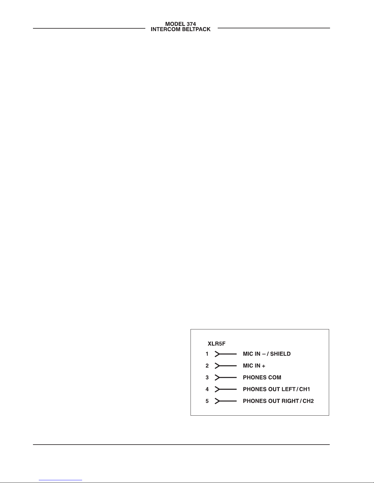
Headset Connection
The Model 374 provides a 5-pin female
XLR connector that interfaces with the
microphone and headphone connections
of an intercom or broadcast-style headset.
Refer to Figure 2 for connection details.
The microphone input connections are
intended for use with unbalanced dynamic
microphones. Balanced microphones
should, in most cases, also function cor-
rectly if the signal – (low) is connected to
Model 374’s mic in –/shield connection.
No support is provided for microphones
that require low-voltage “eletret,” P12
phantom, or P48 phantom powering.
To allow users of stereo (dual-earpiece or
“double muff”) headsets to hear a monau-
ral version of the two headphone output
channels does not require special wiring
of the 5-pin male XLR mating connector.
The headset’s left headphone channel
should always be wired to pin 4 and the
right headphone channel to pin 5. Con-
figuration choices, discussed later in this
guide, can then be used to create the
Figure 2. Headset connection pinout chart

Model 374 User Guide Issue 2, September 2016
Studio Technologies, Inc. Page 9
desired monaural output. It’s important not
to connect together (short) pins 4 and 5
of the Model 374’s headset connector as
damage to the Model 374’s output circuit-
ry could result.
Monaural (single-earpiece or “single
muff”) headsets should be wired such that
its headphone is wired only to pin 4; pin 5
should be remain unused. The configura-
tion mode, discussed later in this guide,
can be used to create a monaural output.
It’s possible that some Beyerdynamic in-
terconnecting cable assemblies terminate
the earpiece’s left and right connections
opposite from what the Model 374 and
other broadcast equipment implements.
This may require “flipping” two wires in
a headset’s 5-pin male XLR connector
so that left and right from the Model 374
match correctly.
Dante Configuration
For audio to pass to and from the Model
374 requires that several Dante-related
parameters be configured. These configu-
ration settings will be stored in non-volatile
memory within the Model 374’s circuitry.
Configuration will typically be done with
the Dante Controller software application
which is available for download free of
charge at www.audinate.com. Versions
of Dante Controller are available to sup-
port Windows® and OS X® operating
systems. The Model 374 uses the Ultimo
4-input/4-output integrated circuit to imple-
ment the Dante architecture.
The four Dante transmitter (Tx) channels
associated with the Model 374’s Dante
interface must be assigned to the desired
receiver channels. This achieves routing
the Model 374’s four talk output audio
channels to the device (or devices) that
will be “listening” to them. Within Dante
Controller a “subscription” is the term
used for routing a transmitter flow (a
group of output channels) to a receiver
flow (a group of input channels). The num-
ber of transmitter flows associated with an
Ultimo integrated circuit is limited to two.
These can either be unicast, multicast,
or a combination of the two. If the Model
374’s transmitter channels need to be
routed to more than two flows it’s possible
that an intermediary device, such as a
rack-mounted digital signal processor unit
with more available flows, can be used to
“repeat” the signals.
The four Dante receiver (Rx) channels
associated with the Model 374’s audio
inputs also need to be routed to the de-
sired Dante transmitter channels. These
four audio signals will be sent to the Model
374’s 2-channel headphone output.
The Model 374 supports audio sample
rates of 44.1 and 48 kHz with a limited
selection of pull-up/pull-down values
available. In most cases the default will be
used and a pull-up or pull-down rate will
not be selected. The Model 374 can serve
as the clock master for a Dante network
but in most cases it will be configured to
“sync” to another device.
The Model 374 has a default Dante device
name of ST-M374 and a unique suffix. The
suffix identifies the specific Model 374 that
is being configured. The suffix’s actual
alpha and/or numeric characters relate
to the MAC address of the unit’s Ultimo
integrated circuit. The four Dante transmit-
ter (Tx) channels have default names of
Ch1, Ch2, Ch3, and Ch4. The four Dante
receiver (Rx) channels have default names
of Ch1, Ch2, Ch3, and Ch4. Using Dante

Issue 2, September 2016 Model 374 User Guide
Page 10 Studio Technologies, Inc.
Controller the default device name and
channel names can be revised as appropri-
ate for the specific application.
Model 374 Configuration
Many of the Model 374’s operating pa-
rameters can be configured to match the
needs of specific applications. The Model
374 provides four DIP switches of which
three are used to configure operating func-
tions. Two switches allow the gain of the
microphone preamplifier to be adjusted.
One switch selects if a special button back-
light mode is enabled. The fourth switch is
not utilized at this time. A software-based
configuration method is used to select the
talk button modes as well as setting the
way in which incoming audio is routed to
the headphone output channels. The DIP
switches and pushbutton switch that en-
ables configuration are accessible from
the back of the unit’s enclosure through
a rectangular opening that is located
under the top of the belt clip.
The DIP switches are connected to the
Model 374’s logic circuitry which responds
to changes by way of the application firm-
ware; no audio passes directly through the
switches. Changes made to a DIP switch
will immediately be reflected in the unit’s
operation. Changes made to the talk button
modes or headphone audio routing will be
incorporated once the configuration pro-
cess has been completed. A power cycle
is not required for configuration changes
to be recognized and implemented
Accessing the DIP Switches and
Configure Button
To access the switches and configure
button requires that the belt clip be
rotated. Normally the belt clip is secured
to the back of the enclosure using one
rivet (non-removable) and one machine
screw that has a thread pitch of 6-32. To
allow the belt clip to rotate, remove the
machine screw using a #1 Phillips head
screw driver. The belt clip should now be
able to rotate in either direction. Save the
screw so that it can be re-installed once
the desired configuration choices have
been made. Note that the threaded fas-
tener within the back of the Model 374’s
chassis has an internal locking mecha-
nism (a plastic bushing) that prevents
the belt clip’s 6-32 machine screw from
vibrating loose. So no additional method
of thread locking, such as a lock washer
or chemical compound, is necessary.
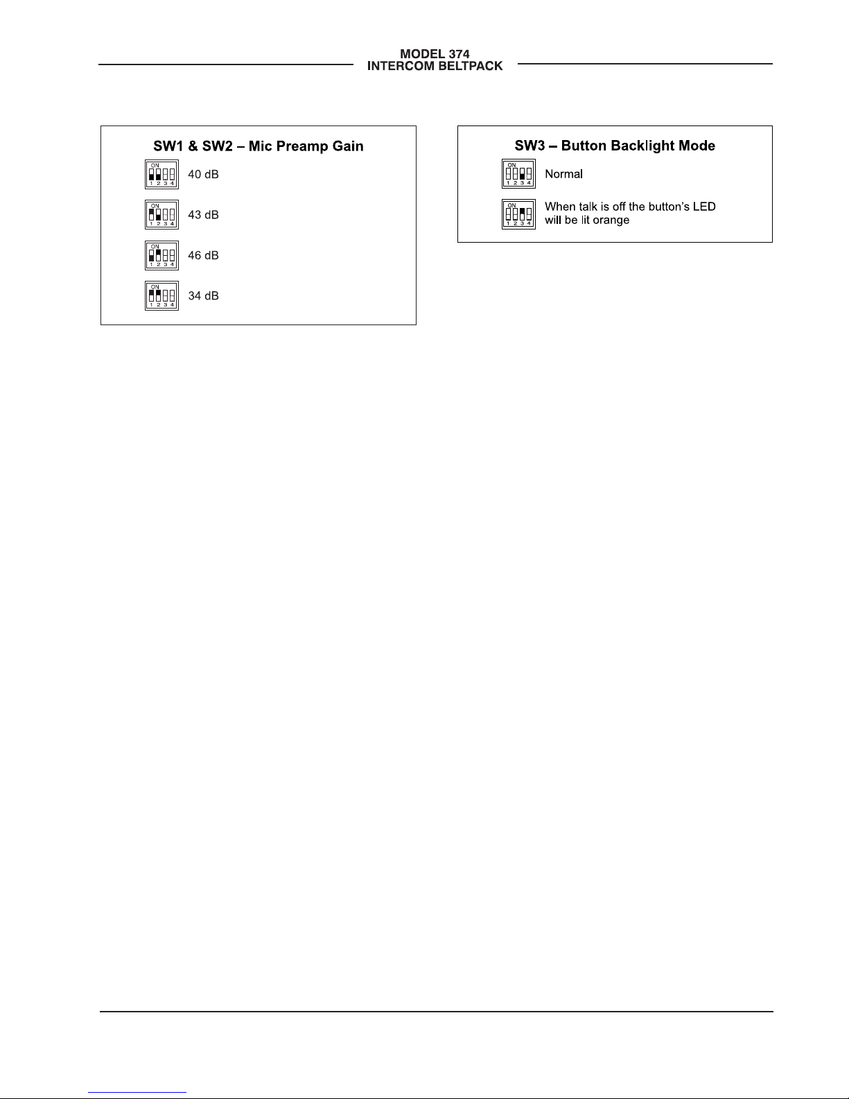
Microphone Preamp Gain
Switches SW1 and SW2 allow the gain of
the microphone preamplifier to be select-
ed. When SW1 and SW2 are in their down
(off) position 40 dB of gain is selected.
This will be appropriate for most applica-
tions. (Technically this gain is approxi-
mately equal to the gain provided within
an RTS® BP-325 analog party-line belt-
pack.) Placing SW1 to its up (on) position
while leaving SW2 in its down (off) posi-
tion selects the 43 dB gain setting. Leav-
ing SW1 to its down (off) position while
placing SW2 in its up (on) position selects
the 46 dB gain setting. This additional 3 or
6 dB of gain may be helpful in some ap-
plications, such as with headsets that have
a low microphone output level. The higher
gain settings may also be useful when
the Model 374 is going to be deployed at
events where users are not able to speak
at normal levels, e.g., sporting events
such as golf tournaments.
Model 374 User Guide Issue 2, September 2016
Studio Technologies, Inc. Page 11
Placing SW1 and SW2 to their up (on)
positions selects the gain to be 34 dB. This
reduced gain setting could be valuable
should the connected microphone have a
high sensitivity (high output level for a giv-
en acoustical input) or an enthusiastic user
routinely talks loudly into the microphone.
The compressor active LED, visible on the
bottom of the Model 374’s enclosure adja-
cent to the headset connector, can act as
a guide when setting the preamp gain. Dur-
ing normal talk operation the compressor
active LED should light intermittently. If, for
example, it rarely lights and the gain is set
to 40 dB, it might be a good idea to change
to setting to 43 or 46 dB. If the LED is lit
fully during normal talking and the gain is
set for 40, 43, or 46 dB, changing it to one
of the lower values might be warranted.
There’s no “hard and fast” rule about which
gain setting is appropriate. But unless oth-
erwise indicated, 40 dB is typically a good
initial choice.
Button Backlight Mode
Switch SW3 controls the button backlight
mode, something that typically will not be
enabled. This special function provides the
user with a positive indication of the real-
time status of the talk on/off buttons. It will
ensure that in most cases each of the four
buttons will have an LED lit at all times.
Normally when a talk channel is enabled
the button’s backlight will be green and
when the channel is not enabled no LED
will be lit. When the button backlight mode
is enabled each button’s orange LED will
be lit when talk is off. In this way each but-
ton will be lit orange for off and green for
on. The only exception is when a button is
configured to act as a channel audio moni-
tor on/off control. In this case the button
backlight mode will not perform any func-
tion for that specific button.
Talk Button and Headphone Audio
Configuration
A miniature pushbutton switch, located
to the right of the four DIP switches,
allows the Model 374 to be placed in its
software-based configuration mode. Two
functions within this configuration mode
allow selecting how the four talk buttons
function as well as configuring how the
four input audio sources are routed to the
2-channel headphone output. The pushbut-
ton switch, accessible only when the belt
clip rotated, is used to enter the configura-
tion mode, move between the functions
being configured, and then return the Mod-
el 374 to normal operation. The four talk
buttons and their associated LEDs, located
on the Model 374’s top panel, are used to
make the specific configuration selections.
Figure 4. Button backlight mode configuration
switch
Figure 3. Microphone preamp gain
configuration switches

Issue 2, September 2016 Model 374 User Guide
Page 12 Studio Technologies, Inc.
Entering Configuration Mode
To enter the configuration mode press
and hold the configure button for a short
period of time. A minimum of 500 mil-
liseconds (1/2 second) is required for
the “press” to be recognized. This was
implemented to ensure that the configura-
tion mode is correctly entered, used, and
exited. Once the configuration mode has
been entered normal Model 374 operation
will cease. No talk audio will be sent out
by way of the Dante transmitter channels;
no Dante receive audio will be sent to the
headphone output channels.
Once the configuration mode has been
entered the currently configured operating
mode for each of the four buttons will be
displayed. Besides displaying the mode
using their backlight LEDs, the buttons
will also be used to change the selected
mode, independently for each channel.
The buttons will light green in 1, 2, 3, or 4
flash sequences that repeat continuously.
Each button indicates how its own mode
has been configured. Refer to Figure 5 for
a description of what each flash sequence
indicates. Press each button to advance
to the next operating mode; each button
will advance from 1 to 2, 2 to 3, 3 to 4, and
then “wrap” from 4 back to 1.
Figure 5. Button mode and audio routing configuration descriptions

Model 374 User Guide Issue 2, September 2016
Studio Technologies, Inc. Page 13
It can seem overwhelming to see all four
buttons flashing in identical or different
sequences. But if one concentrates on
observing only one button at a time it can
be quite simple to understand and use.
Even blocking three of the four buttons
with ones fingers, leaving just one visible,
can be helpful.
Here’s a summary of what each button’s
“flash” pattern will indicate:
• Button flashes green one time:
push to talk.
• Button flashes green two times:
push to talk/tap to latch.
• Button flashes green three times:
talk disabled, no talk output on assoc-
iated output channel; normal audio
monitoring.
• Button flashes green four times:
talk disabled, button acts as audio
monitor on/off control; no talk on that
channel, button controls on/off status
of the audio being sent to the head-
phone output.
When the push to talk mode is selected
the operation is self-explanatory. Only
when a talk button is pressed will talk
audio be sent out its associated Dante
transmitter channel.
When the push to talk/tap to latch mode
is selected a “hybrid” function of sorts is
enabled. Pressing and holding the talk
button will enable audio to be sent out
its associated Dante transmitter chan-
nel. When the button is released audio
will stop being sent out the associated
transmitter channel. Tapping (momen-
tarily pressing) the button will cause the
function to “latch” in the talk active mode.
Again tapping the button will cause
the function to “unlatch” and talk will
no longer be active.
Many applications are best served when
the buttons are configured for push to talk
mode operation. This ensures that a chan-
nel won’t accidentally be left in the talk
mode. But there are certainly valid situ-
ations when the push to talk/tap to latch
mode setting will prove to be very useful.
When the talk disabled mode is selected
microphone audio will not be sent out the
associated Dante transmitter channel. This
can be useful when the input audio from
this channel is going to be monitored but
microphone audio from this specific Model
374 is not allowed to “join” this specific
intercom channel.
When the talk disabled/audio monitor on/
off control mode is selected the button will
not impact talk audio but will instead con-
trol the on/off state of the audio being sent
to the headphone output. In this mode talk
audio will never be sent out the associated
Dante transmitter channel. This is an inter-
esting mode, allowing one or more Model
374 audio channels to serve in a “monitor
mixer” function. The button will allow quick
on/off control while the rotary level control
can remain in its desired position.
Once the appropriate button modes have
been selected the configuration button,
located to the right of the DIP switches,
will be used to move on to the next con-
figuration. Don’t press it yet. Please move
on to the next paragraph of this guide for
details.

Issue 2, September 2016 Model 374 User Guide
Page 14 Studio Technologies, Inc.
Headphone Audio Routing Modes
To leave the talk button operation configu-
ration simply requires one to press and
momentarily hold the configure button.
This will move on to allow configuring the
audio routing to phones mode. The four
talk on/off buttons will display the current
modes for the four audio input channels.
The buttons are also used to change the
configurations as desired. When in this
mode each button will flash orange one,
two, or three times in a continuous se-
quence to display its current setting. Press
each channel button to change to the next
mode — 1 to 2, 2 to 3, and then “wrap”
from 3 back to 1.
Here’s a summary of what each button’s
“flash” pattern will indicate:
• Button flashes orange one time:
audio source sent to left and right
channels of the headphone output.
• Button flashes orange two times:
audio source sent to left channel
of the headphone output.
• Button flashes orange three times:
audio source sent to right channel
of the headphone output.
How the Model 374’s four audio inputs
(Dante receiver channels) are routed to
the headphone output channels can be
configured using this configuration mode.
The choices provide flexibility in how the
audio sources are presented to the user.
When using a stereo (“double muff”)
headset it’s common for the four audio
input sources to always be routed to both
the left and right channels. But the Model
374’s flexibility allows each source to be
independently configured for sending to
the left and right, left only, or right only
headphone channels.
When using a stereo headset sending all
inputs to both channels is often referred
to as a dual-channel mono output. If a
monaural (“single muff”) headset is used
the left only configuration option allows
the four input channels to be combined to
monaural so that the listener can hear all
the sources.
Once any desired changes have been
made this mode can be exited. Refer to the
next paragraphs of this guide for details.
Exiting Configuration and Return to
Normal Operation
Press and momentarily hold the configure
button to leave the audio routing mode.
At this time any changes made to the but-
ton modes and audio routing modes will
be stored in non-volatile memory and nor-
mal Model 374 operation will resume. Any
changes made to the operating modes will
be immediately reflected in how the
unit functions.
Restore Factory Defaults
If you press and hold the configuration but-
ton for 5 seconds the factory default config-
urations will be restored and then saved in
non-volatile memory. The factory configura-
tion settings are push to talk for the buttons
and input audio sent to the left and right
channels of the headphone output.
Inactivity Timer
Whenever a Model 374 is in its configure
mode an inactivity time function will be in
effect. If the function detects that there is
no button-press activity for a continuous
60-second interval the unit will return to
normal operation with no configuration
changes saved.

Model 374 User Guide Issue 2, September 2016
Studio Technologies, Inc. Page 15
Operation
At this point everything should be ready
and Model 374 operation can commence.
An Ethernet connection with Power-over-
Ethernet (PoE) capability should have
been made. Alternately, a midspan power
injector, in “series” with the Ethernet con-
nection, should have been put into place.
A headset terminated on a 5-pin male XLR
connector should be plugged into the
headset connector.
The Model 374’s Dante configuration set-
tings should have been selected using
the Dante Controller software application.
In this way the unit’s four audio output
channels (Dante transmitter channels) and
four audio input channels (Dante receiver
channels) should have been routed to
the receiver and transmitter channels on
associated equipment. The Model 374’s
configuration switches should have been
set and the configuration modes selected
such that the desired operating character-
istics are established.
Initial Operation
The Model 374 will start to function as
soon as a Power-over-Ethernet (PoE)
power source is connected. However, it
may take 20 to 30 seconds for full opera-
tion to commence. Upon initial power
up the three status LEDs located on the
bottom panel below the RJ45 jack will
begin to light as network and Dante con-
nections are established. The green and
orange LED backlights within the four
pushbutton switches on the top panel may
initially light randomly and then will light in
a test sequence to indicate that the main
operating firmware (embedded software)
has started. Once the entire sequence has
completed and the Dante connection has
been established full operation will begin.
Ethernet and Dante Status
LEDs
Three status LEDs are located below the
etherCON RJ45 connector on the Model
374’s bottom panel. The LINK ACT LED
will light green whenever an active con-
nection to a 100 Mb/s Ethernet network
has been established. It will flash in re-
sponse to Ethernet data packet activity.
The SYS and SYNC LEDs display the
operating status of the Dante interface
and associated network. The SYS LED
will light red upon Model 374 power up
to indicate that the Dante interface is not
ready. After a short interval it will light
green to indicate that it is ready to pass
data with another Dante device. The SYNC
LED will light red when the Model 374 is
not synchronized with a Dante network. It
will light solid green when the Model 374
is synchronized with a Dante network and
an external clock source (timing reference)
is being received. It will slowly flash green
when the Model 374 is part of a Dante
network and is serving as a clock master.
It’s possible that up to 30 seconds may
be required for the SYNC LED to reach its
final state.
How to Identify a Specific
Model 374/Remote Talk Off
Function
The Dante Controller software application
offers an identify command that can be
used to help locate a specific Model 374.
When identify is selected it will send a
command to a single Model 374 unit. On
that specific unit the four pushbutton LEDs
will light in a unique pattern. In addition,

Issue 2, September 2016 Model 374 User Guide
Page 16 Studio Technologies, Inc.
the SYS and SYNC status LEDs, located
directly below the etherCON RJ45 con-
nector on the bottom panel, will slowly
flash green. After a few seconds the LED
identification pattern will cease and normal
Model 374 button LED and Dante status
LED operation will resume.
The identify command also causes a talk
off (“mic kill”) function to activate. If any
of the four talk buttons are configured to
the push to talk/tap to latch mode, and
they are latched on, the identify command
will cause them to latch off. This allows
talk channels on a specific Model 374
that have been accidentally enabled to
be remotely turned off.
Listen Level
Four rotary potentiometers (“pots”),
located on the Model 374’s top panel,
allow individual adjustment of the level
of the four audio input signals as they
are sent to the 2-channel headphone
output. Depending on the configuration
of the unit, each audio input can be sent
to both the left and right channels of the
headphone output, to the left headphone
output, or to the right headphone output.
The pots are “push in/push out” type
which allow their associated knobs to be
in their “out” position to be adjusted and
their “in” position when protection from an
unwanted change is desired.
Users should find the headphone output
audio quality to be excellent, with high
maximum output level and low distortion.
Analog audio signals do not pass directly
through the level pots. The position of the
pots is recognized by the Model 374’s
processor which then adjusts the signal
level within the digital domain. When a pot
is in its fully counterclockwise position the
associated audio signal is fully muted. In
most cases the on/off status of the four talk
channels does not impact the headphone
output. However, one configuration setting
assigns the associated button to function
as a channel listen audio on/off selector.
Compressor Active LED
A yellow LED indicator is located on the
bottom panel adjacent to the headset con-
nector. Labeled COMP, the LED displays
the status of the microphone audio com-
pressor function. It will light whenever the
input level from the microphone, along with
the configured mic preamp gain, is such
that the dynamic range of the talk signal is
being controlled. It’s perfectly acceptable
for this LED to light intermittently whenever
a user is talking at a normal voice level
into the associated microphone. But if the
COMP LED lights solid while a user is talk-
ing at a normal voice level this will typically
indicate that the mic gain setting should
be reduced. Conversely, if the COMP LED
almost never lights when normal talking is
taking place, it’s possible that changing the
gain to a higher value would be beneficial.
Note that due to the design of the circuitry
the compressor active LED will function
whether or not any of the four talk channels
are active.
Talk Buttons
Four pushbutton switches are associated
with the Model 374’s four intercom chan-
nels. How they function will depend on the
configuration of the unit. Each button can
be configured independently.
Push to Talk
When a button has been configured for the
push to talk mode how it functions is pretty
self-explanatory. Press and hold the button

Model 374 User Guide Issue 2, September 2016
Studio Technologies, Inc. Page 17
when headset microphone audio is to be
sent out the associated dante audio out-
put channel. The button’s green LED will
light to indicate that the output is active.
Push to Talk/Tap to Latch
If a button has been configured for the
push to talk/tap to latch mode operation
is a bit different and certainly more flex-
ible. Press and hold the button to activate
the talk function. When released the talk
function will turn off. Momentarily pressing
(“tapping”) the button will cause the func-
tion to change states; off-to-on or on-
to-off. Whenever the talk function is active
the green LED will light.
Talk Disabled
A button that is configured to the disabled
mode will never allow talk audio to be sent
to the associated Dante output channel.
But to provide “feedback” that the button
has been pressed the button’s orange
LED will flash rapidly three times. This
says, in effect, “yes, I recognize that you
pressed the button but I’m not going to
do anything in response!”
Talk Disabled/Audio Monitor On/Off
Control
In the talk disabled/audio monitor on/off
control configuration the button will never
allow talk audio to be sent to the associat-
ed Dante output channel. But instead the
button will serve an alternate function,
providing an audio channel on/off func-
tion. The button will always operate in a
tap to latch mode and its orange LED will
light when audio is being sent, by way of
the associated level control, to the head-
phone output. Momentarily pressing
(“tapping”) the button will cause the
phones audio signal to change states;
off-to-on or on-to-off. The exact head-
phone output level will continue to follow
the setting of the rotary level control. But
its overall on/off state will follow that of the
pushbutton.
Sidetone Function
The Model 374 includes a sidetone func-
tion that sends microphone audio to both
the left and right headphone output chan-
nels whenever any of the talk buttons
are active. The audio quality should be
excellent and will provide the Model 374
user with a confidence signal that they
are actively talking to other intercom us-
ers. Sidetone audio is always sent to both
headphone channels and is not a configu-
rable choice. This is because the function
is trying to simulate what a user would
hear if they didn’t have a headset cover-
ing their ears. It is not intended to indicate
to the user which Dante talkback output
channel or channels are actively being
sent audio.
The level of the sidetone audio being sent
to the left and right headphone channels
is adjusted using the rotary level control
(“pot”) that is located on the bottom of the
Model 374’s enclosure. A small straight
blade screwdriver (e.g., a “greenie”) can
be used to adjust the pot. Although with
some practice one’s thumb and index
finger can also be effective. Typically the
exact sidetone level is not critical and
most users will not be concerned about
revising it to a specific value. But setting
the sidetone level to something reason-
able is important. Setting the level too
low will encourage users to speak too
loudly; setting it too high and users will
be tempted to speak hesitantly. The four
headphone level controls on the top panel

Issue 2, September 2016 Model 374 User Guide
Page 18 Studio Technologies, Inc.
of the unit do not impact the sidetone level.
Audio does not pass directly through the
sidetone pot. The pot’s position is moni-
tored by the Model 374’s processor which
then controls the level within the digital
audio domain.
Technical Notes
IP Address Assignment
By default the Model 374’s Ethernet inter-
face will attempt to automatically obtain an
IP address and associated settings using
DHCP (Dynamic Host Configuration Pro-
tocol). If a DHCP server is not detected an
IP address will automatically be assigned
using the link-local protocol. This proto-
col is known in the Microsoft® world as
Automatic Private IP Addressing (APIPA).
It is also sometimes referred to as auto-IP
(PIPPA). Link-local will randomly assign
a unique IP address in the IPv4 range of
169.254.0.1 to 169.254.255.254. In this
way multiple Dante-enabled devices can
be connected together and automatically
function, whether or not a DHCP server is
active on the LAN. Even two Dante-enabled
devices that are directly interconnected us-
ing an RJ45 patch cord will, in most cases,
correctly acquire IP addresses and be able
to communicate with each other.
An exception does arise when trying to
directly interconnect two Dante-enabled
devices that use Ultimo integrated circuits
to implement Dante. The Model 374 uses
the Ultimo “chip” and, as such, a direct
one-to-one interconnection to another
Model 374 (or other Ultimo-based product)
is not supported. An Ethernet switch linking
the two units is required to successfully in-
terconnect two Ultimo-based devices. The
technical reason that a switch is required
relates to the need for a slight latency
(delay) in the data flow. And an Ethernet
switch will provide this. While this is cer-
tainly an anomaly, since PoE power is re-
quired for Model 374 operation it’s highly
unlikely that an application would use two
Model 374 units without a PoE-enabled
Ethernet switch being present.
Using the Dante Controller software ap-
plication the Model 374’s IP address and
related network parameters can be set for
a fixed (static) configuration. While this is a
more involved process than simply letting
DHCP or link-local “do their thing,” if fixed
addressing is necessary then this capabil-
ity is available. But in this case it’s highly
recommended that each unit be physically
marked, e.g., directly using a permanent
marker or “console tape,” with its specific
static IP address. If knowledge of a Model
374’s IP address has been misplaced
there is no reset button or other method
to easily restore the unit to a default IP
setting.
In the unfortunate event that a device’s IP
address is “lost,” the Address Resolution
Protocol (ARP) networking command can
be used to “probe” devices on a network
for this information. For example, in Win-
dows OS the arp –a command can be
used to display a list of LAN information
that includes MAC addresses and cor-
responding IP addresses. The simplest
means of identifying an unknown IP ad-
dress is to create a “mini” LAN with a
small PoE-enabled Ethernet switch con-
necting a personal computer to the Model
374. Then by using the appropriate ARP
command the required “clues” can be
obtained.

Model 374 User Guide Issue 2, September 2016
Studio Technologies, Inc. Page 19
Optimizing Network
Performance
For best Dante audio-over-Ethernet perfor-
mance a network that supports VoIP QoS
capability is recommended. This can typi-
cally be implemented on virtually all con-
temporary managed Ethernet switches.
There are even specialized switches that
are optimized for entertainment-associated
applications. Refer to the Audinate website
(www.audinate.com) for details on optimiz-
ing networks for Dante applications.
Application Firmware Version
Display
As part of the Model 374’s power-up
sequence the unit’s application firmware
(embedded software) version number can
be displayed. This is useful when working
with factory personnel on application sup-
port and troubleshooting. Before connect-
ing the PoE-enabled Ethernet cable, press
and hold the channel 4 talk button. Then
connect the Ethernet cable. Upon applica-
tion of PoE power the Model 374 will go
through its normal power-up sequences
followed by a display of the firmware ver-
sion. The LED associated with the chan-
nel 1 talk button will “flash” to display
the major version number. Then the LED
associated with the channel 2 talk button
will “flash” to display the minor version
number. Once the version number has
been displayed button 4 can be released
and normal operation will begin. As an ex-
ample of what would be a typical firmware
display, if the channel 1 talk button “flash-
es” once followed by the channel 2 talk
button “flashing” three times this would
indicate that application firmware version
1.3 was present in the Model 374.
Application Firmware Update
Procedure
It’s possible that updated versions of the
application firmware (embedded software)
that is utilized by the Model 374’s proces-
sor (microcontroller or MCU) integrated
circuit will be released to add features or
correct issues. Refer to the Studio Tech-
nologies website for the latest application
firmware file. The unit has the ability to
load a revised file into the MCU’s non-vol-
atile memory by way of a USB interface.
The Model 374 implements a USB host
function that directly supports connec-
tion of a USB flash drive. The Model 374’s
MCU updates its firmware using a file
named m374.bin.
The update process begins by preparing
a USB flash drive. The flash drive doesn’t
have to be empty (blank) but must be in
the personal-computer-standard FAT32
format. Save the new firmware file in the
root directory with a name of m374.bin.
Studio Technologies will supply the ap-
plication firmware file inside a .zip archive
file. While the firmware file inside of the zip
file will adhere to the naming convention
required by the Model 374, the name of
the zip file itself will include the file’s ver-
sion number. For example, a file named
m374v1r3MCU.zip would indicate that
version 1.3 of the application firmware
(m374.bin) is contained within this zip file.
Once the USB flash drive is inserted
into the USB interface, located on the
main circuit board under the cover, the
unit must be powered off and again
powered on. At this point the file will auto-
matically load. The precise steps required
will be highlighted in the next paragraphs
of this guide. After the firmware has been

Issue 2, September 2016 Model 374 User Guide
Page 20 Studio Technologies, Inc.
updated the LEDs associated with the
channel 1 and channel 2 talk buttons
should be used to confirm that the desired
application firmware version has been
successfully installed.
To install the application firmware file
follow these steps:
1. Disconnect power from the Model 374.
This will entail removing the Ethernet
connection that is providing PoE
power.
2. Remove the cover from the Model 374.
Begin by removing the four Phillips
head screws (#1 screw driver tip), two
per side. Be certain to save the screws
so that re-assembly will be fast and
painless. Then carefully slide the cover
forward to separate it from the level
controls and buttons and then lift it off.
3. Locate the USB connector on the main
circuit board. It’s near the channel 1
talk button. Insert the prepared USB
flash drive into it.
4. Apply power to the Model 374 by con-
necting to a Power-over-Ethernet (PoE)
Ethernet source.
5. After a few seconds the Model 374 will
run a “boot loader” program that will
automatically load the new application
firmware file (m374.bin). This loading
process will take only a few seconds.
During this time period the channel 4
talk button LED will flash slowly in al-
ternate colors. Once the entire loading
process is over, taking approximately
10 seconds, the Model 374 will restart
using the newly-loaded application
firmware.
6. At this time the Model 374 is function-
ing with the newly-loaded application
firmware and the USB flash drive can
be removed. But to be conservative,
remove PoE power first and then
remove the USB flash drive.
7. To confirm that the desired firmware
version has been correctly loaded,
press and hold the channel 4 talk
button, apply power to the Model 374,
and “read” the application firmware
version number by observing the chan-
nel 1 and channel 2 talk button LEDs.
Ensure that this is the desired version.
Note that upon power being applied to the
Model 374 if a connected USB flash drive
doesn’t have the correct file (m374.bin) in
the root folder no harm will occur. Upon
power up the channel 4 talk button’s LED
will flash on and off rapidly for a few sec-
onds to indicate this condition and then
normal operation using the unit’s existing
application firmware will begin.
Ultimo Firmware Update
As previously discussed in this guide,
the Model 374 implements Dante connec-
tivity using the 4-input/4-output Ultimo
integrated circuit from Audinate. The
Dante Controller software application
can be used to determine the version
of the firmware (embedded software)
residing in the Ultimo “chip.” This firmware
can be updated by way of the Model 374’s
Ethernet connection. The latest Dante
firmware file is available on the Studio
Technologies website. The Dante Firm-
ware Update Manager (FUM) application
is used to install the firmware. This pro-
gram is also available for download on
the Studio Technologies website.
Table of contents
Popular Cables And Connectors manuals by other brands


Amphenol
Amphenol ePower-lite C10-765779-3XS1 instructions

Briteq
Briteq LD-SPLIT IP68 - INSTALLATION V1.0 installation manual

Larson Electronics
Larson Electronics EPCO-20A Series INSTALLATION, OPERATION & MAINTENANCE DATA SHEET

Paradyne
Paradyne BitStorm 6051 installation instructions

Tait
Tait TMAA04-05 installation instructions

EMTELLE
EMTELLE FIBREFLOW Installation And Maintenance Training Manual


