EMTELLE FIBREFLOW Installation guide

INNOVATION AND FLEXIBILITY
“This document is intended as a guide only. Whilst the information it contains is believed to be correct, Emtelle can take no responsibility for actions taken based on the information contained in this document. Emtelle reserves the
right to make changes to this document without notice. All sales of product are subject to Emtelle’s terms and conditions of sale only, which can be found on Emtelle’s website.”
1
INNOVATION IS OUR TRADITION DESIGNED FOR FLEXIBILITY
THE INSTALLATION AND MAINTENANCE TRAINING MANUAL
INNOVATION AND FLEXIBILITY
Issue 7: June 2009
The Installation
And Maintenance Training Manual

INNOVATION AND FLEXIBILITY
THE INSTALLATION AND MAINTENANCE TRAINING MANUAL
Amendment Records
A record of all changes or reprints will be made and recorded in the amendments table below.
Release
Number
Date Details Author Approval
Issue 4 6/05 Review and Release HF D.S.
Issue 5 6/06 Updated Procedures and Equipment HF
Issue 6 1/08 Addition of new products, some procedures removed PJC
Issue 7 6/09 Addition of new products PJC
This document is intended as a guide only. Whilst the information it contains is believed to be correct, Emtelle can take no responsibility for actions
taken based on the information contained in this document. Emtelle reserves the right to make changes to this document without notice. All sales of
product are subject to Emtelle’s terms and conditions of sale only, which can be found on Emtelle’s website.
This document is protected by copyright © Emtelle UK Limited [2008]. The products depicted are protected by intellectual property rights.Any
unauthorized copying of this document or of our products is prohibited and Emtelle UK Limited will take action to prevent any infringement of its
rights and to claim damages for the loss that it suffers
2 INNOVATION AND FLEXIBILITY

INNOVATION AND FLEXIBILITY
THE INSTALLATION AND MAINTENANCE TRAINING MANUAL
Contents
I Amendment records . . . . . . . . . . . . . . . . . . . . . . . . . . . . . . . . .2
II Contents list,page order . . . . . . . . . . . . . . . . . . . . . . . . . . . . . .3
III Preface . . . . . . . . . . . . . . . . . . . . . . . . . . . . . . . . . . . . . . . . . . .5
IV Document Control . . . . . . . . . . . . . . . . . . . . . . . . . . . . . . . . . . .6
1 Risk, Health & Safety . . . . . . . . . . . . . . . . . . . . . . . . . . . . . . . . .7
2 The Last Mile . . . . . . . . . . . . . . . . . . . . . . . . . . . . . . . . . . . . . .11
2.1 Introduction . . . . . . . . . . . . . . . . . . . . . . . . . . . . . . . . . . .11
2.2 Introducing Fibre Unit. . . . . . . . . . . . . . . . . . . . . . . . . . . .11
3 Outdoor installation. . . . . . . . . . . . . . . . . . . . . . . . . . . . . . . . .12
3.1 Tight Protected Microduct (TPM) . . . . . . . . . . . . . . . . . . .12
3.2 Loose Protected Microduct (LPM) . . . . . . . . . . . . . . . . . . .13
3.3 Different ways to create a fibre route . . . . . . . . . . . . . . . .13
3.4 Handling & Deploying Protected Microduct 14
3.5 Drum and Coil Handling: Drums . . . . . . . . . . . . . . . . . . . .14
3.6 Drum and Coil Handling: Coils . . . . . . . . . . . . . . . . . . . . .15
3.7 Direct Burial Installation . . . . . . . . . . . . . . . . . . . . . . . .. 16
Positioning individual cable lengths on-site . . . . . . . . . . .17
Water . . . . . . . . . . . . . . . . . . . . . . . . . . . . . . . . . . . . . . . 17
Sealing the MicroductAssembly End . . . . . . . . . . . . . . . .18
Cable End Sealing – Stretch End Cap . . . . . . . . . . . . . . . .18
Cable End Sealing – Heat Shrink End Cap . . . . . . . . . . . . .20
DB Sequence . . . . . . . . . . . . . . . . . . . . . . . . . . . . . . . . .. 21
Additional Protection . . . . . . . . . . . . . . . . . . . . . . . . . . . .21
Stone Impingement . . . . . . . . . . . . . . . . . . . . . . . . . . . . .22
Thermal Effects. . . . . . . . . . . . . . . . . . . . . . . . . . . . . . . . .22
Conduit Installation . . . . . . . . . . . . . . . . . . . . . . . . . . . . .22
3.8 Direct Installation – Blowing into a subduct . . . . . . . . . . .22
Ducts that are not empty . . . . . . . . . . . . . . . . . . . . . . . . . 22
Direct Installation – Pulling into a duct . . . . . . . . . . . . . . .23
Pull tensions. . . . . . . . . . . . . . . . . . . . . . . . . . . . . . . . . . .24
When Cables Jam . . . . . . . . . . . . . . . . . . . . . . . . . . . . . . .25
Bends . . . . . . . . . . . . . . . . . . . . . . . . . . . . . . . . . . . . . . . 25
Lubricants . . . . . . . . . . . . . . . . . . . . . . . . . . . . . . . . . . . . 25
Swivel and Fuses . . . . . . . . . . . . . . . . . . . . . . . . . . . . . . .26
Installation Guidelines for Direct Installation Products . . .27
Informative Guide to Correct Duct or Conduit Placement
(UK experience) . . . . . . . . . . . . . . . . . . . . . . . . . . . . . . . . 28
3.9
Numbering / Identifi cation ofTight Protected Microduct (TPM)
. .31
3.10Installation into slots . . . . . . . . . . . . . . . . . . . . . . . . . . . .32
3.11Mole Ploughing . . . . . . . . . . . . . . . . . . . . . . . . . . . . . . . .34
3.12 General Installation advice. . . . . . . . . . . . . . . . . . . . . . . .35
storage and handling / installation. . . . . . . .36
3.13Aerial Installations . . . . . . . . . . . . . . . . . . . . . . . . . . . . . .36
4 Indoor installations and LFH products . . . . . . . . . . . . . . . . . . .37
4.1 Building Entry. . . . . . . . . . . . . . . . . . . . . . . . . . . . . . . . . .37
4.2 Indoor installation (LFH) . . . . . . . . . . . . . . . . . . . . . . . . . 38
4.3 Indoor and Vertical Planning Rules . . . . . . . . . . . . . . . . . .39
5 Tube assembly preparation . . . . . . . . . . . . . . . . . . . . . . . . . . .41
5.1 Tools. . . . . . . . . . . . . . . . . . . . . . . . . . . . . . . . . . . . . . . . .41
5.2 DBmf Microduct Assembly Stripping Techniques . . . . . . .42
5.3 Sheath Removal /Window Cutting of Direct Install
and LFH Products . . . . . . . . . . . . . . . . . . . . . . . . . . . . . . .44
5.4 Sheath removal of 1DB 5mm . . . . . . . . . . . . . . . . . . . . . .44
6 ClosuresAnd Their Selection . . . . . . . . . . . . . . . . . . . . . . . . .. 45
6.1 Introduction to Closures for Blown Fibre Installations . . . .45
6.2 Selection charts to help define the correct closure
for each application.. . . . . . . . . . . . . . . . . . . . . . . . . . . . .46
6.3 Closure Assembly: General Instructions . . . . . . . . . . . . . .49
6.4 Building entry Closure Requirements . . . . . . . . . . . . . . . 50
Dual Circuit Box . . . . . . . . . . . . . . . . . . . . . . . . . . . . . . . .51
Multi-Circuit Splicing Point . . . . . . . . . . . . . . . . . . . . . . . .52
6.5 Gas / Water Blocking of Microduct Interstices . . . . . . . . .. 53
6.6 Demarcation methods for microduct assemblies. . . . . . . .54
7 Connectors . . . . . . . . . . . . . . . . . . . . . . . . . . . . . . . . . . . . . . .56
7.1 Straight Connectors . . . . . . . . . . . . . . . . . . . . . . . . . . . . .56
7.2 Reducer Connectors . . . . . . . . . . . . . . . . . . . . . . . . . . . . .57
7.3 End Caps . . . . . . . . . . . . . . . . . . . . . . . . . . . . . . . . . . . . .57
7.4 Collet Locking Tool (7236). . . . . . . . . . . . . . . . . . . . . . . . .58
7.5 The Rounding Tool (7949) . . . . . . . . . . . . . . . . . . . . . . . . .58
7.6 Gas Blocking Connectors . . . . . . . . . . . . . . . . . . . . . . . . .59
7.7 Water Blocking Connectors (for 2 & 4 fibre units only) . . .61
7.8 Barb Insert 5mm – 3mm ~ for 2 and 4 fi bre units only . . .62
7.9 FTTH Reducing Connector, 3mm (7513) . . . . . . . . . . . . . .62
7.10Closedown Connectors (2A and 3A) . . . . . . . . . . . . . . . . .63
7.11 Slimline Bulkhead Connector (7248). . . . . . . . . . . . . . . . .68
8 Fibre UnitsAnd Fibre Handling . . . . . . . . . . . . . . . . . . . . . . . . .65
8.1 Emtelle Fibre Units (FU) . . . . . . . . . . . . . . . . . . . . . . . . . .65
8.2 Bend Radius Notes for Emtelle Fibre Units. . . . . . . . . . . . .65
8.3 Other Technical Data. . . . . . . . . . . . . . . . . . . . . . . . . . . . .66
8.4 Pans and Packaging . . . . . . . . . . . . . . . . . . . . . . . . . . . . .66
8.5 Fibre Stripping Instructions . . . . . . . . . . . . . . . . . . . . . . . .67
8.6 Fibre Colour Configurations . . . . . . . . . . . . . . . . . . . . . . .68
8.7 DriveWheels and Plates . . . . . . . . . . . . . . . . . . . . . . . . . . .69
8.8 Beads . . . . . . . . . . . . . . . . . . . . . . . . . . . . . . . . . . . . . . . .70
8.9 Fibre Restraint . . . . . . . . . . . . . . . . . . . . . . . . . . . . . . . . . .71
9 Fibre Blowing . . . . . . . . . . . . . . . . . . . . . . . . . . . . . . . . . . . . .73
9.1 The Blowing Principles . . . . . . . . . . . . . . . . . . . . . . . . . . .73
9.2 The Blowing Set-Up . . . . . . . . . . . . . . . . . . . . . . . . . . . . .74
9.3 Performance – How Far Will it Blow? . . . . . . . . . . . . . . . .74
9.4 Bends in the Route . . . . . . . . . . . . . . . . . . . . . . . . . . . . . .75
9.5 Blowing through unequal m/d Sizes . . . . . . . . . . . . . . . . .76
9.6 Compressors . . . . . . . . . . . . . . . . . . . . . . . . . . . . . . . . . .77
9.7 Compressed Air Data . . . . . . . . . . . . . . . . . . . . . . . . . . . .78
9.8 Air Preparation Kit and Off-Shelf Compressors . . . . . . . .. 79
9.9 Blowing Performance and Installation Distance . . . . . . . .80
9.10 Bend Radius for FU and Microduct . . . . . . . . . . . . . . . . . .81
9.11 Blowing equipment for FU . . . . . . . . . . . . . . . . . . . . . . . .82
“This document is intended as a guide only. Whilst the information it contains is believed to be correct, Emtelle can take no responsibility for actions taken based on the information contained in this document. Emtelle reserves the
right to make changes to this document without notice. All sales of product are subject to Emtelle’s terms and conditions of sale only, which can be found on Emtelle’s website.”
3
INNOVATION AND FLEXIBILITY

INNOVATION AND FLEXIBILITY
THE INSTALLATION AND MAINTENANCE TRAINING MANUAL
Contents
Air Flow testing . . . . . . . . . . . . . . . . . . . . . . . . . . . . . . . .83
PressureTesting . . . . . . . . . . . . . . . . . . . . . . . . . . . . . . . . . . . . 85
ContinuityTest . . . . . . . . . . . . . . . . . . . . . . . . . . . . . . . . .86
Continuity Fault Finding . . . . . . . . . . . . . . . . . . . . . . . . . .87
Air Flow Charts. . . . . . . . . . . . . . . . . . . . . . . . . . . . . . . . .88
9.12 Blowing equipment for fibre unit installation . 89
Blowing unit 2a (7016) . . . . . . . . . . . . . . . . . . . . . . . . . . . . . . 89
Blowing unit 2a – Blowing Head. . . . . . . . . . . . . . . . . . . .91
Blowing Head set up. . . . . . . . . . . . . . . . . . . . . . . . . . . . .92
Buckle Detector Operation . . . . . . . . . . . . . . . . . . . . . . . .93
Blowing Head control unit . . . . . . . . . . . . . . . . . . . . . . . . . . . 93
The 15 Bar Dispenser (7855) . . . . . . . . . . . . . . . . . . . . . . . . . . 94
Flow Meter Kit (7778) . . . . . . . . . . . . . . . . . . . . . . . . . . . . . . . 95
Fibre coiler 1a (7004) . . . . . . . . . . . . . . . . . . . . . . . . . . . . . . . . 96
9.13 Fibre Blowing Methods . . . . . . . . . . . . . . . . . . . . . . . . . .99
Point to Point Blowing . . . . . . . . . . . . . . . . . . . . . . . . . . . . . . . 99
Onward Blowing . . . . . . . . . . . . . . . . . . . . . . . . . . . . . . . . . . . 100
Centre Blowing. . . . . . . . . . . . . . . . . . . . . . . . . . . . . . . .101
Tandem Blowing . . . . . . . . . . . . . . . . . . . . . . . . . . . . . . . . . . . 104
Troubleshooting Guide . . . . . . . . . . . . . . . . . . . . . . . . . .105
Water in the Microduct . . . . . . . . . . . . . . . . . . . . . . . . . .114
10 Maintenance of installation equipment . . . . . . . 107
10.1Blowing Head. . . . . . . . . . . . . . . . . . . . . . . . . . . . . . . . . . . . . . 107
10.2The Coiler . . . . . . . . . . . . . . . . . . . . . . . . . . . . . . . . . . . . . . . . . 111
11 Repair Procedures . . . . . . . . . . . . . . . . . . . . . . . . . . 113
11.1 Repairs to DB Bundles . . . . . . . . . . . . . . . . . . . . . . . . . . . . . . 113
11.2 Repair Procedure for 1 DB Joint (code 7787) . . . . . . . . . . . 117
Appendix – Product Code IdentificationTable . . . . . . . . . . . . . . . . . 118
Terminology: IEC 60794 has defined that ‘tubes’ in the context of blown fibre products, shall be named ‘microducts’, since they are used as
ducts, awaiting the installation of micro-sized fibre cables (units) The abbreviation ‘m/d’ may be used henceforward, to mean ‘microduct’
“This document is intended as a guide only. Whilst the information it contains is believed to be correct, Emtelle can take no responsibility for actions taken based on the information contained in this document. Emtelle reserves the
right to make changes to this document without notice. All sales of product are subject to Emtelle’s terms and conditions of sale only, which can be found on Emtelle’s website.”
4 INNOVATION AND FLEXIBILITY

INNOVATION AND FLEXIBILITY
THE INSTALLATION AND MAINTENANCE TRAINING MANUALTHE INSTALLATION AND MAINTENANCE TRAINING MANUAL
Preface
Introduction
The Installation and MaintenanceTraining Manual (now referred to as I & M) is intended for network installers who wish to deploy
fibre bundles through empty microducts (m/d) by means of compressed air.
Overview of the I & M
The I & M is intended to be used as a stand alone document and should be used as an aide- memoire to the course. All information contained within is
included for guidance only. The web page or the technical department should be consulted for current information. Should specific information not be
included within this document,it may be sourced by contacting theTechnical Department. Contact details may be found at the rear of the preface.
Purpose, Scope and Objectives
The purpose of the manual is to teach the correct fibre bundle installation practice by means of compressed air. The course will include the following;
■Health and safety aspects as they relate to blown fibre bundle (Fibre units) installation
■Preparation of tube bundles (Protected MicroductAssemblies)
■Handling, deploying and testing tube bundles
■Microduct Connectors and Enclosures
■Installation Procedures
■Operation of blowing equipment and its maintenance
■BlowingTechniques
■Product Code Listings
If the candidate passes the I and M assessment he will be awarded Emtelle’s Installation and Maintenance Certificate.
Training Schedule and Cost Summary
The I & M training will be carried out at Emtelle in Hawick or at the Customer’s Location. An appropriate fee will be ascertained and made available
upon request.
“This document is intended as a guide only. Whilst the information it contains is believed to be correct, Emtelle can take no responsibility for actions taken based on the information contained in this document. Emtelle reserves the
right to make changes to this document without notice. All sales of product are subject to Emtelle’s terms and conditions of sale only, which can be found on Emtelle’s website.”
5
INNOVATION AND FLEXIBILITY
Installation Practice
Installation of the Materials must be undertaken by a Registered Installer, in strict accordance with the Emtelle InstallersTraining Manual and in
compliance with the Network design requirements detailed in the Design and Engineering Manual.
In particular installers must comply with the minimum bend radii for various microducts, tube bundles and fibre units, as specified in the relevant
product data sheet. Further, the microducts and tube bundles shall remain closed to the external environment and free of any contaminants which
may partially or totally obstruct the bore of the microduct or adversely affect the microduct and in particular the inner layer of the microduct.The
microduct must not be subject to excessive compression such that the bore is restricted.
Materials are to be installed and used in both physical conditions and an environment which are suitable for their use and which are in all respects
suitable to protect the Materials from corrosion or deterioration from natural or artificial causes,compression or damage howsoever caused.
Installation of fibre products,break-out of fibres and storage of fibres,must also be carried out in accordance with the Design and Engineering
Manual by a Registered Installer using Emtelle installation equipment.All installation equipment shall be maintained in accordance with
the relevant Emtelle maintenance guidelines detailed in the InstallerTraining Manual.
The fibre products must not be exposed to aggressive contaminants, including but not limited to acid or alkaline solutions, organic reagents, ionising
and non-ionising radiation.
Only Emtelle approved products supplied by Emtelle or a duly authorised distributor of Emtelle products may be installed in the Network
and in particular, all microducts, tube bundles,microduct connectors,microduct closures, fibre products including fibre bundle and fibre optic cable,
and blowing equipment.

INNOVATION AND FLEXIBILITY
THE INSTALLATION AND MAINTENANCE TRAINING MANUAL
Document Control
Issue Management
All issues will be controlled by the author and approved by theTechnical Director.
Revision History
All revisions shall be documented and shown on the inside front page of the manual.
Document Storage
This document was created in theTechnical Department using Word and the file is stored under
T: Services andTraining / I&M / I&M – Issue 6
Document Owner
Company Details
Emtelle UK Limited
Haughhead
Hawick
Scotland
TD9 8LF
Tel: +44 (0) 1450 364 000
Fax: +44(0) 1450 364 001
www.emtelle.com
“This document is intended as a guide only. Whilst the information it contains is believed to be correct, Emtelle can take no responsibility for actions taken based on the information contained in this document. Emtelle reserves the
right to make changes to this document without notice. All sales of product are subject to Emtelle’s terms and conditions of sale only, which can be found on Emtelle’s website.”
6 INNOVATION AND FLEXIBILITY

INNOVATION AND FLEXIBILITY
THE INSTALLATION AND MAINTENANCE TRAINING MANUAL
1 Risk, Health & Safety
Emtelle supports the implementation of the Health and Safety atWorksAct 1974 which requires the Employer to safeguard so far as is
reasonably practicable the health, safety and welfare of all the people who work for him.
What that implies is that Emtelle comply with the following;
■ Provide a safe working environment.
■ Provide safe tools and equipment.
■ Provide safe methods of work.
■ Provide safe access and egress.
■ Provide safe handling, storage and transport of articles and substances.
■ Provide necessary information.
■ Instruction, training and supervision.
The Health and Safety at Work act also requires that an employer must,
■ Ensure,so far as is reasonably practicable,the health and safety of people not in his employment but who may be affected by the work he is
carrying out
There is moreover an obligation on the employee,
■ To take reasonable care of him/her self and of other persons who may be affected by his acts or omissions.
■ To co-operate with his employer in meeting legal requirements.
Failure to follow safety regulations and recommendations could result in injury
Safety is paramount to Emtelle and it is taken seriously within the company. Information relevant to your training will be given by theTrainer but
information can also be found.
■ On Notice Boards throughout the factory.
■ Around Buildings – Safety signs,notices,etc.
InstallationTechnicians and Engineers are reminded that they must obey general as well as specialised safety recommendations and everyone must
obey the rules governing safety in the event of a fire.
General Safety
■ Walk – Do NOT run.
■ Keep all corridors, passages and access ways clear.
■ Keep all Fire Exits clear and do NOT leave Fire Doors open.
■ Do NOT obstruct Fire Fighting Equipment.
■ Clean up spillages as soon as they occur.
■ Do NOT stand on chairs,desks etc – use stepladders.
■ Use the correct tools and equipment for the task and wear the appropriate PPE (personal Protective Equipment) as directed.
■ Take note of any instruction and any safety information which may be issued from time to time.
This manual is intended to give technicians working with products essential information and advice as it relates to the efficient and
safe working practice of procedures described within. It is expected that each individual will make a risk assessment on any part of the work carried
out to highlight any possible causes for concern.
“This document is intended as a guide only. Whilst the information it contains is believed to be correct, Emtelle can take no responsibility for actions taken based on the information contained in this document. Emtelle reserves the
right to make changes to this document without notice. All sales of product are subject to Emtelle’s terms and conditions of sale only, which can be found on Emtelle’s website.”
7
INNOVATION AND FLEXIBILITY

INNOVATION AND FLEXIBILITY
THE INSTALLATION AND MAINTENANCE TRAINING MANUAL
1 Risk, Health & Safety
The assessments of risks are listed below:
■ Injury due to incorrect lifting and manual handling
• Compressor to and from van.
• Unloading large or heavy drums.
■ Injury to back or fingers when removing / replacing manhole lids
• Use correct tools,mechanical aids and methods.
■ Injury due to slips, trips and falls
• Keep cables and hoses away from walking routes.
• Be careful around open manholes,dug holes and trenches.
■ Injury due to poor communication between team members
• Keep in touch (maybe on the phone) to tell the others helping what is happening,especially if equipment is about to ‘go’,or large drums are
about to rotate.
■ Always use correct cable and fibre handling tools and Protective Equipment
• Strip coatings off fibre units with the correct tool. Small pieces of optical fibre present a great hazard, they can easily stick into hands and
fingers and due to their size and brittleness are difficult to remove
• Optical fibre is almost invisible due to the purity of the glass. It may be invisible if it finds its way into the eye and therefore extremely difficult to
remove.
•Always wear suitable eye protection when working with fibres.
• Use a CIN BIN (sharps bin) for disposal of small pieces of fibre. Do not leave them on the floor or place them into a waste paper bin.
• Using knife blades to cut cable insulations is hazardous. Use tools illustrated.
•Take care when using heat to seal heat-shrink closures and sleeves.
■ Equipment Operational Safety
• Before commencing blowing familiarise yourself with the environment, carry out a risk assessment and implement control procedures e.g.
signage and guarding.
• Before operating any equipment ensure no-one is at risk.
• Operate the equipment only in accordance with the operating instructions.
• In the event of a malfunction, stop the machine and have any defects rectified before the machine is re-used.
■ Transportation Safety
•When transporting equipment ensure that it is secure and will not move during transit.
•Avoid carrying petrol but if needed ensure any petrol is contained within a proper can and made secure for transit. A fire extinguisher is
necessary.
• Ensure a means of communication is made available if travelling off site.
■ Traffic Management
• Signage and Guarding must comply with the New StreetWorksAct (1991).
“This document is intended as a guide only. Whilst the information it contains is believed to be correct, Emtelle can take no responsibility for actions taken based on the information contained in this document. Emtelle reserves the
right to make changes to this document without notice. All sales of product are subject to Emtelle’s terms and conditions of sale only, which can be found on Emtelle’s website.”
8 INNOVATION AND FLEXIBILITY

INNOVATION AND FLEXIBILITY
Emergency Procedures
THE INSTALLATION AND MAINTENANCE TRAINING MANUAL
You must know what to do in the event of an emergency;
■ In the event of FIRE
•The alarm sounds like a high pitched ringing siren.
• Evacuate the building by the nearest exit. Leave all belongings.
• Do not attempt to tackle the fire unless you can use the equipment and your life is in no danger.
• Muster at the designated Muster Point.
■ If you need First Aid
• See your trainer and he will locate a first aider.
• If a serious accident has occurred and you need to call an ambulance dial 9999.
■ If someone suffers an electric shock
• Isolate yourself.
• Switch off the power.
• Seek a first aider.
Issues when Working with Compressed Air
Pressurised air must be treated with great respect and care
• Ensure all fittings and m/d ends are free from contamination before making connections.
• Ensure all fittings are approved by Emtelle.
• Ensure all fittings about to be pressurised are secure.
• Ensure m/ds are not cut or damaged before pressurisation.
• Do not put exhaust m/ds or fittings near the face.
• Do not disconnect hoses,open blow heads or closures etc until depressurised.
• Never fool around with air jets,they can be dangerous.
• Never exceed 15 bar pressure for external m/d products or 10 bar pressure for internal m/d products.
Safety When Working in Manholes and Access Chambers
It is important that safety precautions are taken whenever working in‘deep’ manholes,both for those directly involved, and the general public in the
vicinity.
It is never safe to assume that the ‘air’ below the lid you lift is normal air as in the street. Many underground gases can seep into chambers and pits
and make the air unbreathable or even explosive.
Hazards
■ Physical matters as previously discussed.
■ Water-filled manholes.
•Water filled manholes should be pumped out. There may be a legal / local requirement to dispose of this water so check with the local authority.
■ Asphyxiating gas presence or lack of oxygen.
■ Explosive or flammable gas presence.
■ FirstAid and illness.
• Manholes and sub-ground cavities can contain contaminated water.Cuts etc incurred shall be disinfected and treated without delay. Flu-like
symptoms could indicate ‘rat flu’ from infected rat urine.This is a serious condition; explain the full circumstances to a doctor without delay.
• Be prepared to carry out resuscitation or first-aid if someone becomes unconscious.
The Site Manager
In general, the manholes are the responsibility of the site manager, and we work to his authority. It is therefore normal that safe working practices
and equipment be the responsibility of that manager. He should advise Emtelle employees of the equipment and procedures to be used. Otherwise,
Emtelle employees should REQUEST such aid before beginning work. Equipment on loan to Emtelle shall be verified as in good order, complete,
calibrated etc.
EMTELLE EMPLOYEES SHALL NOT IGNORE CORRECT MANHOLE SAFETY PROCEDURES
“This document is intended as a guide only. Whilst the information it contains is believed to be correct, Emtelle can take no responsibility for actions taken based on the information contained in this document. Emtelle reserves the
right to make changes to this document without notice. All sales of product are subject to Emtelle’s terms and conditions of sale only, which can be found on Emtelle’s website.”
9
INNOVATION AND FLEXIBILITY

INNOVATION AND FLEXIBILITY
THE INSTALLATION AND MAINTENANCE TRAINING MANUAL
Civils Matters
■ Working areas including manhole sites shall be coned off or guarded to warn traffic and deter access by the public, especially children.
■ Manholes should not be left open and unattended if it can be avoided, especially at night or weekend.
■ Emtelle employees shall use only the correct manhole lifting gear to lift lids etc. Generally this means cleaning out grab holes and using correct
lift levers,typically two people per lid. If any lid is stuck fast, help shall be requested. Never risk back injury or other strain.Do not risk trapping
fingers when handling lids.Do not have lids or other heavy items balanced unsecured over an occupied hole.Do not leave lids on loose earth by
the hole.
Opening Manholes
Generally, it is important to judge the apparent level of risk:
■ If the manhole is full of water,get it pumped out. No gas risk is likely while the water is present. Do not enter a deep water-filled manhole under
any circumstances.Also, assume all water is contaminated.
■ If the manhole/chamber is shallow (street at chest height or lower when stood inside) then leaving the lid off for 20 minutes should disperse all
gases present.
■ Deep,mostly dry manholes,especially when greater than man-depth, are to be treated with caution, due to the possible presence of flammable
and/or disabling gases.Two people must be present when opening these. Put out cigarettes.Never use a naked flame of any kind or climb inside
within seconds of removing such a lid. Perform gas testing as described below.
Gas Testing
Use an approved Gas Detection Unit (GDU), equipped to identify oxygen levels and the presence of flammable gas. Only enter manholes when it is
totally safe.
If you leave the site for a while then return
Re-test the chamber, as gas can have seeped into it from the ducts.
If gas does return in this way, contact the site manager.
Emergency Procedures
“This document is intended as a guide only. Whilst the information it contains is believed to be correct, Emtelle can take no responsibility for actions taken based on the information contained in this document. Emtelle reserves the
right to make changes to this document without notice. All sales of product are subject to Emtelle’s terms and conditions of sale only, which can be found on Emtelle’s website.”
10 INNOVATION AND FLEXIBILITY
INNOVATION AND FLEXIBILITY
THE INSTALLATION AND MAINTENANCE TRAINING MANUAL
2 The Last Mile
2.1 Introduction –
How is fibreflow different from traditional optical installations?
Wide Area City to city High Fibre counts
Big cables
No connections
Local Area PoP to customer Low Fibre counts
Small cables
Hundreds of connections
One of the problems for the Last Mile (TheAccess Network) is the ever-changing requirement for new connections to an existing system.With
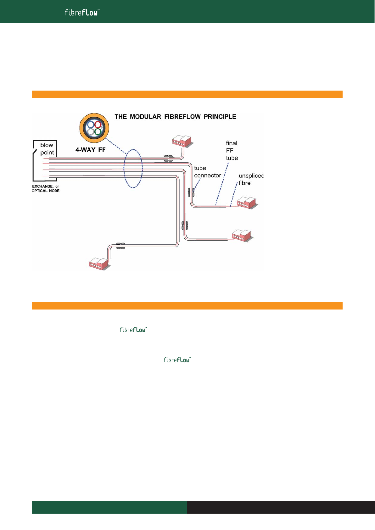
traditional fibre cables,these additions would involve splices and a great deal of re-digging (the most expensive part of the project)
But using a modular system of tubes,called microducts (m/d) additions can be made simply, and with no need for splices. FU can be blown right
through the whole route,even if it consists of five pieces of m/d, linked together with connectors.
2.2 Introducing Fibre Unit
Traditional fibre optic cables contain strength members to protect the delicate glass fibre from installation tensions. Glass breaks at only 2.5%
elongation, so traditional optical cables contain steel wires or GRP rods to protect the optical fibres from damage.
The concept of fibre units is based around fibre cables with no tensile reinforcement. Since they are blown into waiting microducts, they require
NO TENSILE forces to install them.
Consequently fibre units (FU) are very small, typically 1 or 1.5mm in diameter.
Fibre units form the basis for Blown Fibre installations into the Access network, and a full chapter on FUs appears later in this manual.
“This document is intended as a guide only. Whilst the information it contains is believed to be correct, Emtelle can take no responsibility for actions taken based on the information contained in this document. Emtelle reserves the
right to make changes to this document without notice. All sales of product are subject to Emtelle’s terms and conditions of sale only, which can be found on Emtelle’s website.”
11
INNOVATION AND FLEXIBILITY
INNOVATION AND FLEXIBILITY
THE INSTALLATION AND MAINTENANCE TRAINING MANUAL
3 Outdoor Installation
3.1 Tight Protected Microduct (TPM)
The protected microduct is the heart of the system.The polyethylene tubing is used as a fibre pathway, providing enhanced performance
when used for fibre blowing.Microducts are bundled untwisted in various combinations to give product assemblies for installation into the network.
All microducts (m/d) are suitable for use with standard push fit connectors,creating a totally modular system. Connections made like this can be buried
and forgotten,as FU will pass through them later.The‘Standard’ system microducts have an outside diameter of 5mm and an inside
diameter of 3.5mm.Smaller ones are outside diameter 3mm and inside diameter 2.1mm.The construction of these bundles can be one of the following:
■ Direct Install (DI)
■ Direct Bury (DB)
■ Low Fire Hazard (LFH)
■ Plenum Rated (PL) (not 5mm or 3mm)
■ Metal Free Products (eg DBmf)
Emtelle can manufacture tube bundles using larger microduct sizes eg 10mm,12mm, and can also manufacture other type of sheathing for both the
standard microducts and the larger microducts.Other sheathing systems are:
■ Low Fire Hazard Reinforced (LFR)
■ Direct Bury Reinforced (DBR)
■ Direct Bury Termite Resistant (DBT)
■ Direct Bury Reinforced Termite Resistant (DBRT)
■ Aerial or outdoor deployment
■ Petrochemical Resistant
■ Anti-Tracking
2 The Last Mile
“This document is intended as a guide only. Whilst the information it contains is believed to be correct, Emtelle can take no responsibility for actions taken based on the information contained in this document. Emtelle reserves the
right to make changes to this document without notice. All sales of product are subject to Emtelle’s terms and conditions of sale only, which can be found on Emtelle’s website.”
12 INNOVATION AND FLEXIBILITY
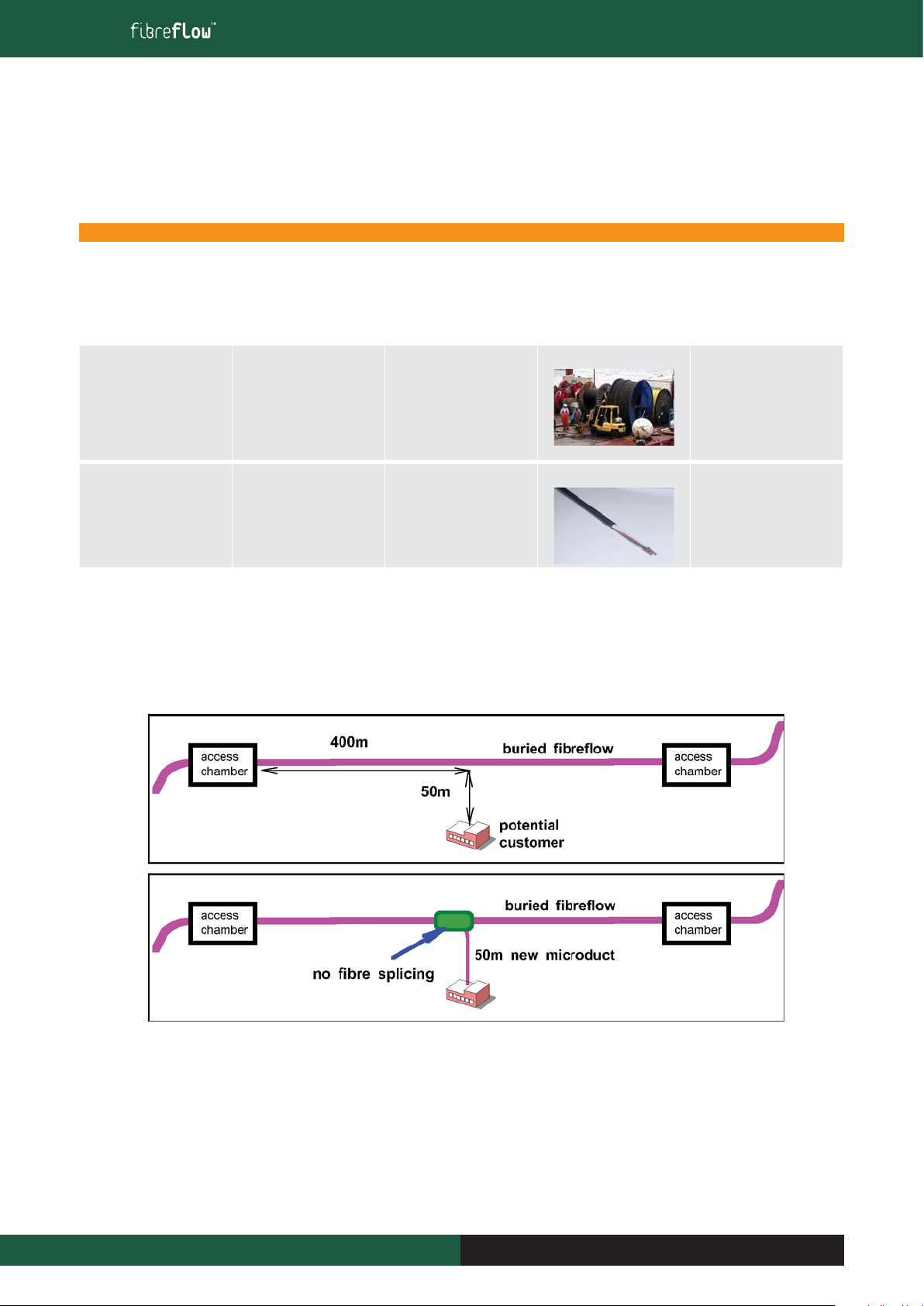
Installation of
Blown Fibre
Since blown fibre is based on the
later adding of fibres to a pre-
installed tube route,the installation
methods are rather different to
those for power or fibre cables.See
in the sketch how tube bundles
branch off BEFORE the customer
building,to permit smooth curving
routes for the travelling fibres.
Remember that installing the tube
bundles is not the last operation,
but that fibres have to be able to
negotiate the route the installer has
created.See section 3.8 for more
information.
Note:
Please refer to Installation Practice
Clause on Page 5.
INNOVATION AND FLEXIBILITY
THE INSTALLATION AND MAINTENANCE TRAINING MANUAL
3 Outdoor Installation
3.2 Loose Protected Microduct (LPM)
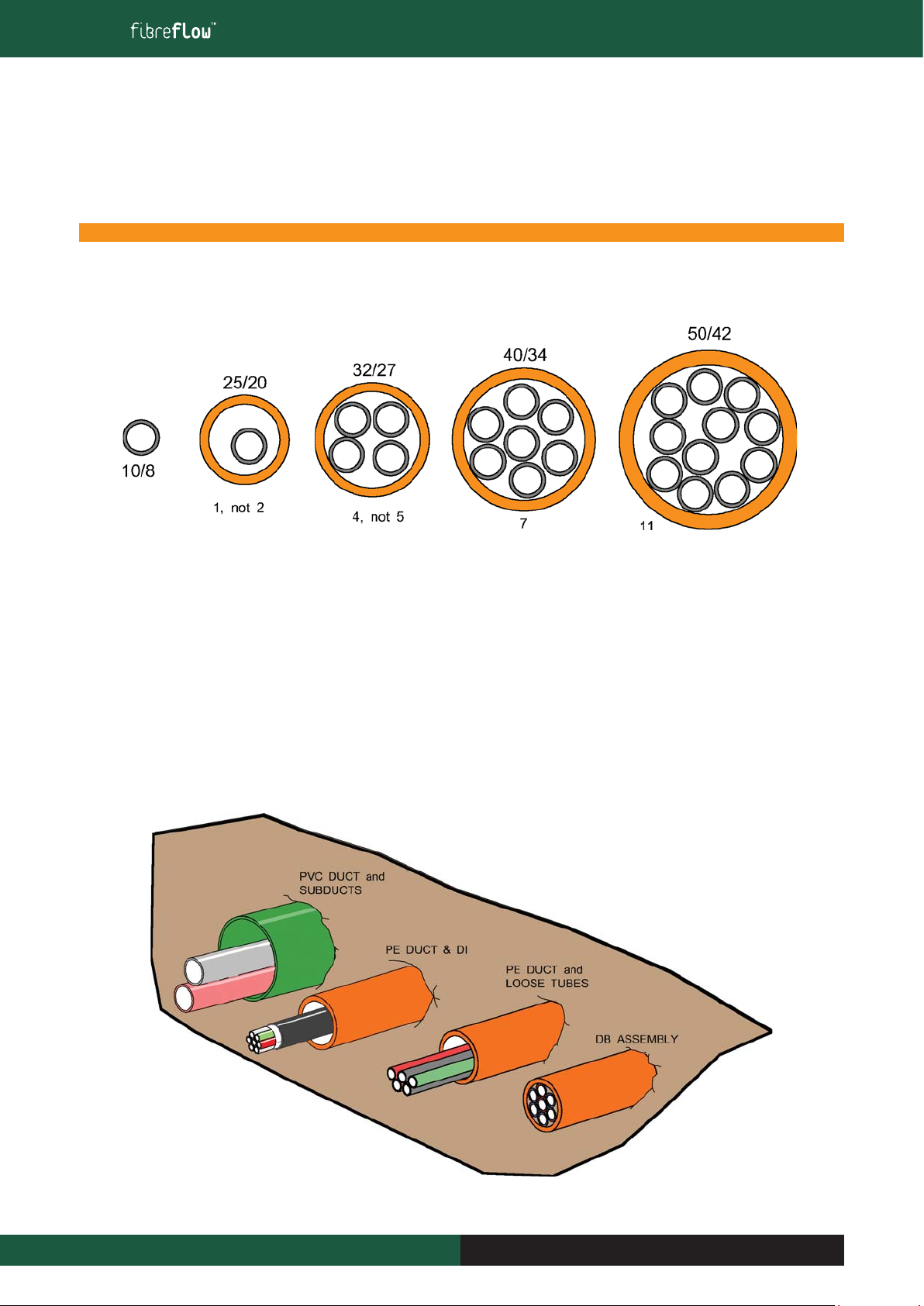
Using four standard duct sizes,and usually 10mm or 12mm m/d, in any reasonable combination: eg:
3.3 Different ways to create a fibre route:
a) A PVC duct carrying other sub-ducts in turn carrying large fibre cables (eg FEEDER networks)
b) Buried PE duct, used to carry either a fibre cable, or a DI bundle.The DI bundle is lightweight and flexible, and relies on the PE duct for its main
protection.
c) Buried PE duct with loose protected m/d (LPM) inside.The advantage is that almost any combination of m/d numbers and sizes can be
accommodated, as above.
d) A simple method to bury bundles of m/d for FU blowing or mini-cable blowing:The DB bundle.
Emtelle provide all these solutions,but the SIZE of the optical element usually determines the carrier duct or micro-duct: Eg:
For heavy fibre cable, eg 300 fibres, install them directly into a buried PE duct
For mini-cables, between 24f and 96f, blow these into 10mm or 12mm bundles in either LPM or TPM versions.
“This document is intended as a guide only. Whilst the information it contains is believed to be correct, Emtelle can take no responsibility for actions taken based on the information contained in this document. Emtelle reserves the
right to make changes to this document without notice. All sales of product are subject to Emtelle’s terms and conditions of sale only, which can be found on Emtelle’s website.”
13
INNOVATION AND FLEXIBILITY
“This document is intended as a guide only. Whilst the information it contains is believed to be correct, Emtelle can take no responsibility for actions taken based on the information contained in this document. Emtelle reserves the
right to make changes to this document without notice. All sales of product are subject to Emtelle’s terms and conditions of sale only, which can be found on Emtelle’s website.”
14
THE INSTALLATION AND MAINTENANCE TRAINING MANUAL
INNOVATION AND FLEXIBILITY
3.4 Handling, & Deploying Protected Microduct
For to be installed correctly and to ensure satisfactory performance for the full designed lifetime, the code of practice outlined in this
manual should be followed.
Risks and Health and Safety
The procedures summarized in this manual assume that all personnel instructed to perform this work are fully trained in the handling and installation
of cables and sub-duct and follow correct safety procedures as outlined in Risks and Safety Section at the start of this manual.
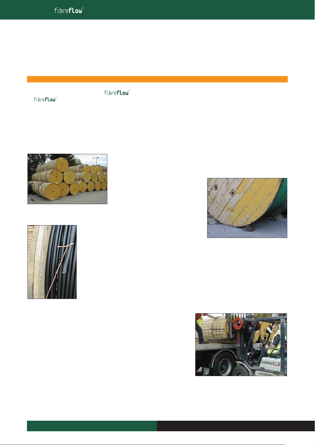
3.5 Drum and Coil Handling: Drums
Drums with full battens can be stored on top of each other on a level stable surface.Drum or pallet
stacks should not exceed 3 metres high. Drums must be secured at the base with correct size chocks.
Drums without battens should be stored just one
metre high and secured with chocks. It must not be
possible for the drum to be pushed over the chock.
Leave the heat shrink end cap in place until the protected microduct product has been installed. Blowing into clean
tubes is best.
Deploy the protected microduct from the drum or trailer so it lies straight. Make a long figure of‘8’ on the ground (i.e.
twist free) if necessary. If deploying protected microduct from a rotating drum into a trench or duct, ensure the drum
stand or trailer is firmly located, and that the rotation will not cause any problem. Consider the pulling force that may
be applied from the other end.
Drum Handling on Site
Drums should be loaded and unloaded from the wagon with the correct lifting machine.This
will typically be a fork lift truck. Never drop the drums off the wagon to the ground and if you
require assistance ask for it.
3 Outdoor Installation

“This document is intended as a guide only. Whilst the information it contains is believed to be correct, Emtelle can take no responsibility for actions taken based on the information contained in this document. Emtelle reserves the
right to make changes to this document without notice. All sales of product are subject to Emtelle’s terms and conditions of sale only, which can be found on Emtelle’s website.”
15
THE INSTALLATION AND MAINTENANCE TRAINING MANUAL
INNOVATION AND FLEXIBILITY
3 Outdoor Installation
Small drums can be rolled carefully to the installation point but never let drums roll freely down a
slope. In all other cases use a drum trailer or similar arrangement. Remove any battens only when
ready to install.
Do not lie the drum flat and pull coils off, as
these corkscrew twists will not ‘pull out’, the
microduct product will not lie flat and this will
cause installation problems or microduct
assembly damage.
3.6 Drum and Coil Handling: Coils
Deployment of 1DB to many houses in one area can potentially involve a high number of drums.
Emtelle provides such product in coils,which eliminates the problem of handling and disposal of
such drums.Coil weights are low and do not require lifting equipment.The Emtelle trolley carries
and deploys 1DB in a controlled way, and is light enough to deploy single-handed. See the relevant
instruction sheet.
Remember to handle the coils sensibly, so that they fit well onto the trolley
and are not seriously distorted.
Low Fire Hazard Products must be stored indoors, as they have limited
UV (daylight) resistance.
Storage and DeploymentTemperatures: see page 36

INNOVATION AND FLEXIBILITY
THE INSTALLATION AND MAINTENANCE TRAINING MANUAL
3.7 Direct Burial Installation (from a drum or a trolley)
Products for direct burial may be ‘loose’ or ‘tight’ (as defined in IEC 60794-5):
TPM =Tight Protected Microduct.These‘DB’ microduct bundles are fixed in place inside the tough outer sheath, and the bundle may also include
filler material, foam, tapes and metal foil.The options are all geometrically ‘standard’, eg 7-way, 12-way 19-way, and each bundle is minimal in
diameter.
LPM = Loose Protected Microduct.The microducts along with no other elements, are free to move inside a sheath that is essentially a polythene
subduct.These products are installed in the same way as PE subducts.In fact they look and behave very much like DB. One difference is that the
individual m/d inside can be custom-specified with respect to number and size: whatever will fit conveniently inside the duct.And of course they have
no fixed ‘position’ or configuration, and must be identified individually at the break-out stage.
■ Direct BuryTPM and LPM protected microduct may be buried directly into suitably prepared ground.
■ Burying 3 to 4 feet deep (0.9m to 1.2m) may help prevent environmental hazards including freezing water, crushing rocky soil, ground disruption
from rodents or construction work.
■ Trench width is normally no less than 10 inches (0.25m)
■ Trenches should be kept narrow unless extra width for personnel is needed at some point.
■ Maintain a regular and flat trench bottom so that the assembly is fully supported before backfilling begins.
■ The protected microduct should have an even covering all around for at least 4” (0.1m) of sand or pea gravel to guarantee a problem free
installation.This includes avoiding frozen lumps of sand,if dug in sub-zero conditions.
■ Compacting onto a badly undulating m/d bundle can cause serious distortion which will
affect blowing performance.
■ Microduct fibre units blow better through straight microducts and around smooth large
radius bends. Leave trench
space for appropriate
bend radii when changing
direction, so protected
microducts can make
comfortable bends.
3 Outdoor Installation
“This document is intended as a guide only. Whilst the information it contains is believed to be correct, Emtelle can take no responsibility for actions taken based on the information contained in this document. Emtelle reserves the
right to make changes to this document without notice. All sales of product are subject to Emtelle’s terms and conditions of sale only, which can be found on Emtelle’s website.”
16 INNOVATION AND FLEXIBILITY
INNOVATION AND FLEXIBILITY
THE INSTALLATION AND MAINTENANCE TRAINING MANUAL
3.7.1 Positioning individual cable lengths on-site:
When installing a m/d assembly cable, leave sufficient length at each chamber or hole for future operations.This may mean just passing the
cable through the access point, or it may mean creating a wave or loop to increase the eventual m/d lengths for termination.
Sequencing:
When installing the protected microduct whether into a trench, duct or cable tray (or other), always install the tube bundles in one
direction otherwise the primary m/ds will not line up.This will mean crossing m/d over, causing connectorisation problems, congestion, and
increasing the time to make a m/d joint.
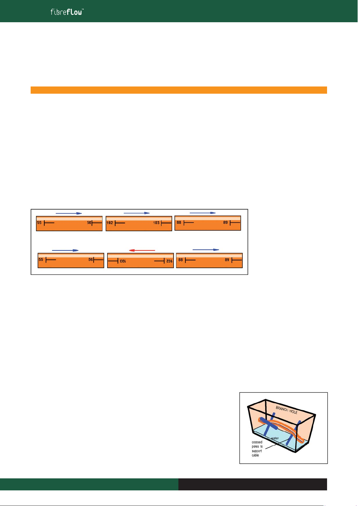
Use the printed metre marks to determine the direction of each piece of DB.
It may not be that all lengths are exactly sequential. For example, if the last length in a street needs to be 150m long, and there is only 100m
left on the current drum, the 150m will come from the next drum. But ensure it lies in the same ‘metre-mark’ orientation as the adjacent
lengths.
Good DB sequence (all L-to-R)
Poor sequence. M/ds will cross over
3.7.2 Water
It is common to find water in holes or chambers at branch or cable join points, and to minimise problems which may arise due to water
contamination, there are important things to do:
■ Do not cut or break into m/d assembly cables at these places until it is necessary.
■ At the time to cut or branch, pump out any standing water if possible.
■ Before working on a m/d assembly cable, cover the hole/chamber with a tent (especially if rain is likely)
■ Arrange the m/d assembly cable working position ‘above ground’, e.g. use double cross bars as per diagram shown or similar so cables do not
lie on the ground/in the water.
■ If a m/d assembly cable end has to be created by cutting through the continuous cable, fit a sealing end cap until time to ‘work’ on the m/d
assembly cable end.
■ If cut m/d assembly cables have to be left overnight or longer, always seal ends to prevent water ingress.
REMEMBER: if water finds its way into primary m/ds, it will have to be removed before fibre
unit or mini cable blowing can begin, and prevention of this by capping will avoid time spent in
decontamination.
3 Outdoor Installation
“This document is intended as a guide only. Whilst the information it contains is believed to be correct, Emtelle can take no responsibility for actions taken based on the information contained in this document. Emtelle reserves the
right to make changes to this document without notice. All sales of product are subject to Emtelle’s terms and conditions of sale only, which can be found on Emtelle’s website.”
17
INNOVATION AND FLEXIBILITY
INNOVATION AND FLEXIBILITY
THE INSTALLATION AND MAINTENANCE TRAINING MANUAL
3.7.3 Sealing the m/d Assembly End
If there is a capped cable end at a chamber or hole, do not cut the cap off until access to the inner is required. Cut off the m/d assembly end and
cap, exposing the individual primary m/ds, remove some sheath, and then cap each m/d with an end cap connector until needed so it becomes
water-resistant.
The m/d cutter should always be used for making a clean cut on the
end of the m/d before inserting into any connector. Always try to cut
the m/d at a 90° angle.
3.7.4 Cable End Sealing – Stretch End Cap
The purpose of this instruction is to demonstrate the method of sealing a microduct
assembly using a cold applied end cap. The instructions that follow are based on
sealing a 24DB 3/2.1 microduct assembly but the procedure can be adopted for any
assembly end provided that the correct size of stretch end cap is available.
This procedure is strongly recommended by Emtelle when using the
system to inhibit water penetration into the tube bundles.The product can be used in
manholes,hand holes and in trenches.
SAFETY: ENSURE LATEX GLOVES ARE WORN WHEN USING THIS
PRODUCT
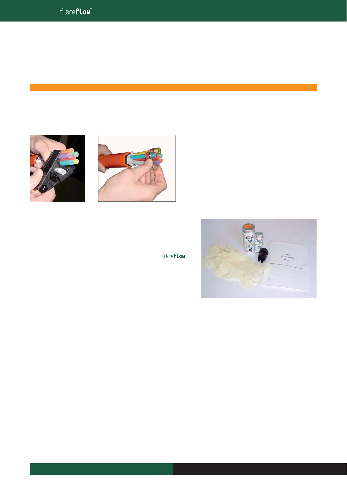
Items Required
Latex Gloves 14454
Stretch End Cap,21-29mm, (size 2) 7278
Resin Pack 9B 7077
Please read the health & Safety Instructions supplied and obey all disposal regulations.
Before using the product the microduct assembly must be free from water and dirt. If it is not wipe it with a cloth and ensure it is dry. Check that the
resin 9B is within its shelf life. The expiry date is found on the lid of the Resin tin.
3 Outdoor Installation
“This document is intended as a guide only. Whilst the information it contains is believed to be correct, Emtelle can take no responsibility for actions taken based on the information contained in this document. Emtelle reserves the
right to make changes to this document without notice. All sales of product are subject to Emtelle’s terms and conditions of sale only, which can be found on Emtelle’s website.”
18 INNOVATION AND FLEXIBILITY
INNOVATION AND FLEXIBILITY
THE INSTALLATION AND MAINTENANCE TRAINING MANUAL
Stretch End Caps Available
Stretch End Cap (38-45) 7730
Stretch End Cap (29-38) 7729
Stretch End Cap (21-29) 7728
Stretch End Cap (15-21) 7726
Stretch End Cap (10-16) 7724
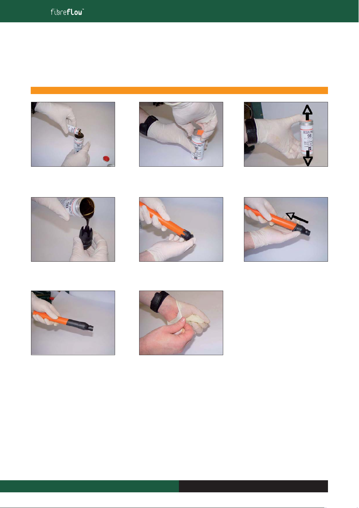
1. Pour the small tin of hardener into the
larger tin containing the resin.
4.Pour the resin into the stretch cap to just
under the widest point of the stretch cap.
7.When completed,the rubber should be fully
unrolled as shown.
2. Screw the top back onto the large tin
5. Push the cap as far as possible onto the
m/d bundle.
8. Dispose of Gloves and empty tins in
accordance with local authority regulations.
3. Shake the tin of resin up and down for
1minute
6. Begin to roll the rubber on the end cap
along the m/d bundle sheath.
3 Outdoor Installation
“This document is intended as a guide only. Whilst the information it contains is believed to be correct, Emtelle can take no responsibility for actions taken based on the information contained in this document. Emtelle reserves the
right to make changes to this document without notice. All sales of product are subject to Emtelle’s terms and conditions of sale only, which can be found on Emtelle’s website.”
19
INNOVATION AND FLEXIBILITY

INNOVATION AND FLEXIBILITY
THE INSTALLATION AND MAINTENANCE TRAINING MANUAL
3.7.5 Cable End Sealing – Heat Shrink End Cap
The purpose of this instruction is to demonstrate the method of applying a heat shrink end cap to the end of a m/d assembly.
Re-capping with an end cap is especially important if the microduct assembly is to pass through a subduct, or trench filled with water or mud.
Preparing the assembly end is important and it must be clean, smooth and dry. If it is greasy, use a solvent wipe to remove it.
A flame should be applied over the sheath for 3 or 4 seconds to prepare it for adhesion. Polyethylene does not adhere well so this step helps to make
a strong bond. Be careful not to melt the polyethylene when using the flame or heated items.
Fit the correct size of end cap (who’s free shrunk size would be less than the microduct assembly diameter) over the end and heat it with a flame or
heat gun.
Heat should be applied evenly to the whole of the cap surface,starting with the closed end, to ensure regular shrinking,and melting of the inner hot-
melt adhesive. When fully cool, check the cap does not pull off, otherwise re-clean, check cap sizes and repeat.
Under no circumstance should the end be taped, e.g.do not use electrical insulation tape.During installation it will form a plug and jam the cable.
Equipment Required Product Code
Heat source N/A
Heat Shrink End Cap (57 - 22mm*) 7480
Heat Shrink End Cap (40 – 17mm) 7588
Heat Shrink End Cap (36 -15mm) 7057
Heat Shrink End Cap (20 – 8mm) 7058
* size ‘before’ and ‘after’ shrinking, so select a cap whos
smaller diameter is LESS than the cable being capped.
1. Place cap onto the end of the m/d
assembly requiring sealing.Apply the
heat evenly over the entire cap surface.
2.Wait for the end cap to cool before
handling or burying.
3 Outdoor Installation
“This document is intended as a guide only. Whilst the information it contains is believed to be correct, Emtelle can take no responsibility for actions taken based on the information contained in this document. Emtelle reserves the
right to make changes to this document without notice. All sales of product are subject to Emtelle’s terms and conditions of sale only, which can be found on Emtelle’s website.”
20 INNOVATION AND FLEXIBILITY
Table of contents
Popular Cables And Connectors manuals by other brands

Burndy
Burndy Continental Industries thermOweld CR-5 instructions

Panduit
Panduit KMTRTH installation instructions

Pressalit
Pressalit R8491 Mounting instruction

Philips
Philips SWV3511NZ Specifications

Eaton
Eaton COOPER POWER SERIES Assembly/installation instructions

Tektronix
Tektronix P6105A instruction manual


National Instruments
National Instruments SH160DIN-4XDB50F-2A installation instructions

Philips
Philips SDW5206GN Specifications

Ophit
Ophit DHPS user guide

Nederman
Nederman 744 Series Original user manual

Digitus
Digitus DA-70130-4 Quick installation guide

Cadman
Cadman 4000M OPERATOR'S PARTS and MAINTENANCE MANUAL