Product Registration
Please register your product via the online form at www.actisense.com/
support/prodreg.
Your product package includes a unit serial number. The serial number is six
digits long and can be found below the barcode on the label. Your registration
will assist Actisense Support to link your product to your details, simplifying any
future assistance you may require.
Product Guarantee
All Actisense products are provided with a 3 year guarantee as standard. To
activate the 5-year guarantee offered with this product please complete
product registration either online at www.actisense.com/support/prodreg or by
completing and returning the warranty card supplied in the box with the product.
If you suspect that the unit is faulty please refer to the Troubleshooting Section
of the User Manual before contacting support.
It is a requirement of the guarantee that all installations of electronic equipment
follow the NMEA 0400 specication. Any connection to a battery or power
supply must meet the mandatory essential safety requirements that may be
imposed by local regulatory agencies.
Actisense products are intended for use in a marine environment, primarily for
below deck use. If a product is to be used in a more severe environment, such
use may be considered misuse under the Active Research Ltd guarantee.
Important Notices
The device to which this manual relates complies with the Electromagnetic
Compatibility requirements according to:
IEC60945:2002-08, DNVGL-CG-0339:2019 & IACS UR E10 Rev7. The unit
should always be used in conjunction with appropriately approved, shielded
cable and connectors as per NMEA 0400 to ensure compliance. A declaration
of conformity is available for download at www.actisense.com.
If the device to which this manual relates is to be installed within ve metres
of a compass, please refer to the ‘Compass Safe Distance’ section in the
‘Technical Specications’ table.
Trademarks and Registered Trademarks
Actisense®and the Actisense logo are registered trademarks of Active Research
Limited (Ltd). All other trademarks are the property of their respective owners.
The NMEA®name and NMEA logo are copyright held by the NMEA. All uses in
this manual are by permission and no claim on the right to the NMEA name or
logo are made in this manual.
Fair Use Statement
The contents of this manual may not be transferred or copied without the
express written permission of Active Research Ltd.
Copyright © 2021 Active Research Ltd. All rights reserved.
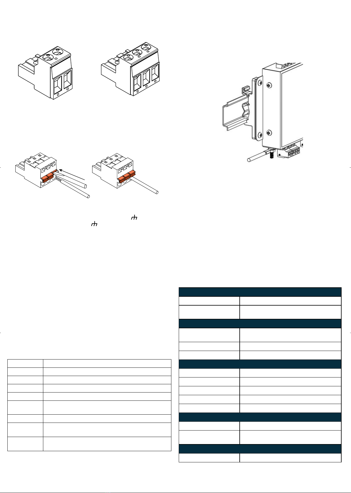
Before getting started
The wire colours used in this quick start guide are in accordance with
the NMEA 0183 specication (v.4.10, June 2014) and are for illustration
purposes only. Please ensure you check the wiring colours in the installation
instructions for the devices you wish to interface to the PRO-BUF-2.
Introduction & Features
PRO-BUF-2 is reliable, robust, type approved device which provides industry
leading isolation on all inputs and outputs as standard, enabling safe connection
of all devices and avoiding hazardous ground loops. With two NMEA 0183
inputs, twelve NMEA 0183 outputs, a bi-directional serial port and an Ethernet
port, the PRO-BUF-2 is a perfect solution for large networks on commercial
shipping, class society vessels and leisure vessels.
The PRO-BUF-2 is designed to suit the majority of NMEA 0183 systems and
ready to go ‘out of the box’ by simply hard-wiring the two mode inputs as
required which can drastically reduce installation time with no complicated
setup required. Helpful LEDs indicate power, data in, data out, status and the
alarm status to aid diagnostics.
Technical Accuracy
To the best of our knowledge the information contained in this document was
correct at the time it was produced. Active Research Ltd cannot accept liability
for any inaccuracies or omissions.
The products described in this manual and the specications thereof may be
changed without prior notice. Active Research Ltd cannot accept any liability
for differences between the product and this document. To check for updated
information and specications please check actisense.com.
Active Research Ltd will not be liable for infringement of copyright, industrial
property rights, or other rights of a third party caused by the use of information
or drawings described in this manual.
Product Disposal
Please dispose of this product in accordance with the WEEE Directive. The
product should be taken to a registered establishment for the disposal of
electronic equipment.
Intelligent Type Approved
NMEA Buffer
Quick Start Guide
PRO-BUF-2
®
Issue 1.05
Active Research Ltd
21 Harwell Road
Poole
Dorset
UK, BH17 0GE
Tel: +44 (0)1202 746682
Web: www.actisense.com
Connect without limits