Studio Technologies 207 eSports Console User manual

Copyright © 2021 by Studio Technologies, Inc., all rights reserved
studio-tech.com
User Guide
Issue 3, March 2021
This User Guide is applicable for serial numbers
M207-00151 and later with application firmware 1.2 and later
50648-0321, Issue 3
Model 207 eSports Console

This page intentionally left blank.

Model 207 User Guide Issue 3, March 2021
Studio Technologies, Inc. Page 3
MODEL 207
eSPORTS CONSOLE
Table of Contents
Revision History ........................................................... 4
Introduction ................................................................... 5
Getting Started ............................................................. 8
Operation ...................................................................... 19
Technical Notes ............................................................ 23
Specifications ............................................................... 27
Appendix A ................................................................... 28

Issue 3, March 2021 Model 207 User Guide
Page 4 Studio Technologies, Inc.
MODEL 207
eSPORTS CONSOLE
Revision History
Issue 3, March 2021:
• Updated document for clarity and consistency.
Issue 2, June 2019:
• Documents addition of Fixed Ch 3 & 4 Level headphone feature.
Issue 1, May 2019:
• Documents miscellaneous perfomance improvements.
Issue Preliminary 1, April 2019:
• Initial release.
Model 207 User Guide Issue 3, March 2021
Studio Technologies, Inc. Page 5
MODEL 207
eSPORTS CONSOLE
Introduction
The Model 207 eSports Console offers a
unique combination of analog and digital
audio resources specifically intended to
support eSports-related live event, entertain-
ment, and streaming broadcast applications.
The unit is housed in a compact, rugged
steel enclosure that’s intended for table-top
use. Its diminutive size also makes it ideal
for use in space-constrained locations. Blue
LED lights cast a distinctive “underglow”
from the bottom of the enclosure. The Model
207 supports Dante® audio-over-Ethernet
digital media technology with AES67 com-
patibility for integration into contemporary
applications. The unit is extremely simple
to deploy, is “pro” quality throughout, and
provides an intuitive user experience. The
Model 207’s audio quality is excellent, with
low distortion, low noise, and ample head-
room. Careful circuit design and rugged
components ensure long, reliable operation.
The Model 207 integrates directly into both
Dante audio-over-Ethernet and standard an-
alog audio environments. With just a Power-
over-Ethernet (PoE) connection, a broadcast
or “gaming” headset, and a connection to a
stereo line-level audio source, a complete
player position can be created.
Model 207 operating features are configured
using the STcontroller software application.
An extensive set of parameters allows the
unit’s functions to be tailored to meet the
needs of many applications. STcontroller is
a fast and simple means of confirming and
revising the unit’s operating parameters.
Applications
The Model 207 on its own can provide an
“all-Dante” solution for one game player
location. The unit’s small size makes it ideal
for live applications where physical space
for personnel is very limited. Four Dante
receiver (input) channels supply the user
with their talent cue (IFB) signals. Should
the cue signal be “mix-minus” an integrated
sidetone function can provide the user with
a microphone confidence signal. Two Dante
audio output channels are associated with a
connected headset’s microphone, one des-
ignated as main and the other as talkback.
Two additional Dante outputs have signal
sources derived from the Model 207’s stereo
line input. These two audio channels, typi-
cally provided by a personal computer, can
also be routed to the headphone output. The
four Dante transmitter (output) channels are
routed via an associated local area network
(LAN) to inputs on Dante-compatible de-
vices. Two pushbutton switches, main and
talkback, provide the user with direct control
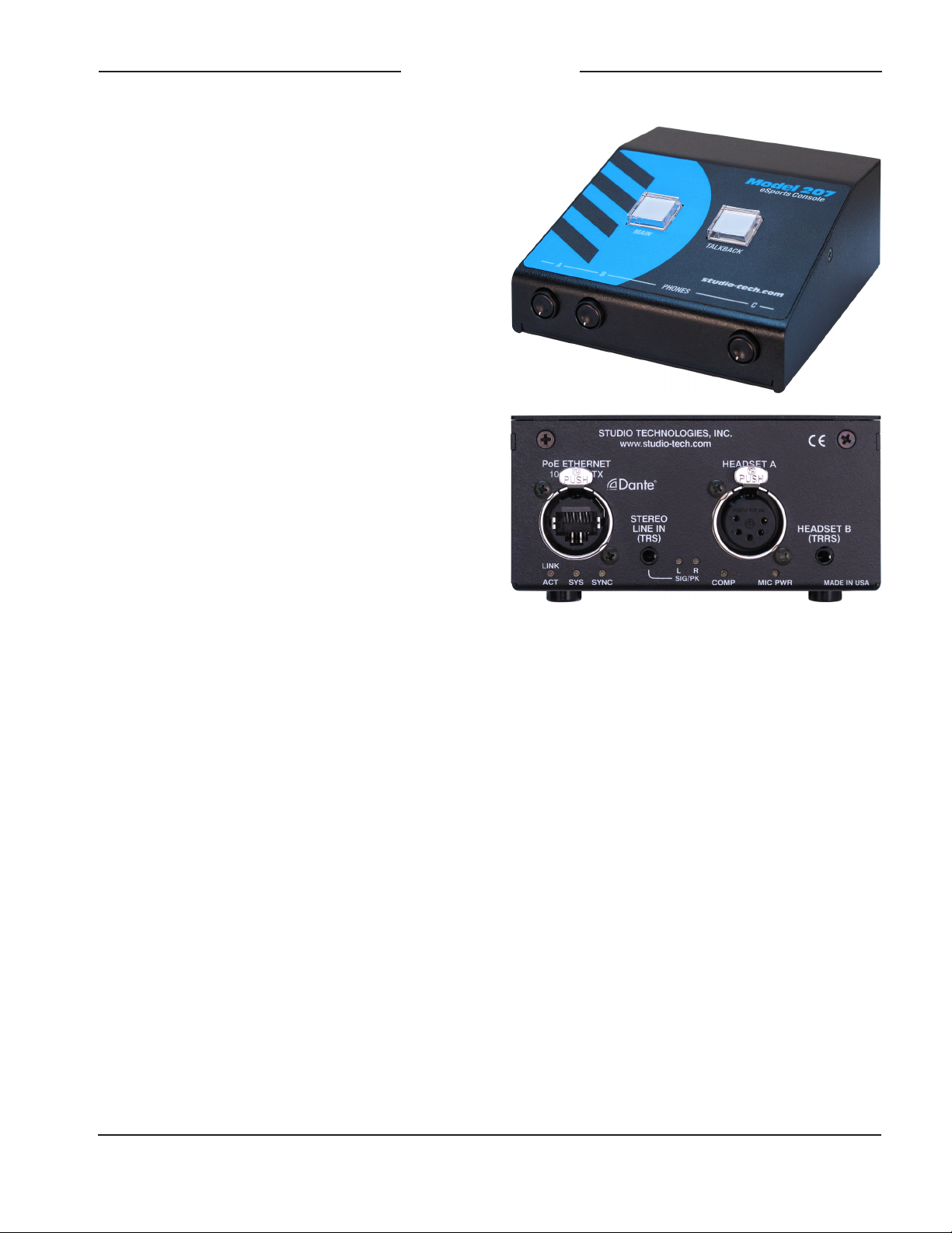
Figure 1. Model 207 eSports Console front and
back views

Issue 3, March 2021 Model 207 User Guide
Page 6 Studio Technologies, Inc.
MODEL 207
eSPORTS CONSOLE
over audio routing. The audio switching is
performed in the digital domain and is virtu-
ally “click-free.” Three rotary controls allow
the user to create their own headphone
audio mix.
Setup and Operation
Set up, configuration, and operation of the
Model 207 is simple. An etherCON® RJ45
jack is used to interconnect with a standard
twisted-pair Ethernet port associated with a
PoE-enabled network switch. This connec-
tion provides both power and bidirectional
digital audio.
A dual-channel (dual-ear or “stereo”) broad-
cast headset can be directly connected to
the unit’s 5-pin female XLR connector. In
addition, a 3.5 mm 4-conductor TRRS jack
allows direct connection of gaming-style
headsets. For each headset type, the micro-
phone input is compatible with dynamic or
electret microphones. The integrated low-
voltage DC source provides power support
for electret microphones.
A 3.5 mm 3-conductor TRS jack supports
connection of a computer’s analog line-level
audio output. The Model 207 takes this
computer audio source and makes it part of
the Dante audio network by first converting
it to digital and then outputting it by way of
two Dante transmitter (output) channels. The
audio from the stereo line input can also be
configured to be part of the sidetone confir-
mation signal that is sent to the headphone
output.
The STcontroller software application is used
to configure the wide range of Model 207
operating parameters. This allows the unit’s
performance to be optimized to meet the
needs of specific applications.
The user is presented with two pushbutton
switches and three push-in/push-out rotary
level potentiometers. This makes it easy to
control the status of the main and talkback
outputs as well as adjusting the signals that
are sent to the headphone output channels.
Ethernet Data and PoE
The Model 207 connects to a local area net-
work (LAN) by way of a standard 100 Mb/s
twisted-pair Ethernet interface. The physical
100BASE-TX interconnection is made by way
of a Neutrik® etherCON RJ45 connector.
While compatible with standard RJ45 plugs,
etherCON allows a ruggedized and locking
interconnection for harsh or high-reliability
environments.
The Model 207’s operating power is provided
by way of the Ethernet interface using the
802.3af Power-over-Ethernet (PoE) standard.
This allows fast and efficient interconnection
with the associated data network. To support
PoE power management, the Model 207’s
PoE interface enumerates (reports) to the
power sourcing equipment (PSE) that it’s a
class 2 (low power) device. If a PoE-enabled
Ethernet port can’t be provided by the associ-
ated Ethernet switch a low-cost PoE midspan
power injector can be utilized.
Dante Audio-over-Ethernet
Audio data is sent to and received from
the Model 207 using the Dante audio-over-
Ethernet media networking technology. As
a Dante-compliant device, the Model 207’s
two Dante transmitter (output) channels and
four Dante receiver (input) channels can be
assigned (routed or “subscribed”) to other
devices using the Dante Controller software
application. The Dante transmitter (output)
and receiver (input) channels are limited to
supporting four Dante flows, two in each
direction. The digital audio’s bit depth is up
to 24 with a sampling rate of 44.1 or 48 kHz.
Two bi-color LEDs provide an indication of
the Dante connection status. An additional

Model 207 User Guide Issue 3, March 2021
Studio Technologies, Inc. Page 7
MODEL 207
eSPORTS CONSOLE
LED displays the status of the associated
Ethernet connection.
The Model 207 is compatible with the AES67
interoperability standard. In addition, the unit
is compatible with the Dante Domain Man-
ager™ (DDM) software application.
Audio Quality
The Model 207’s audio performance is
completely “pro.” A low-noise, wide dynamic-
range microphone preamplifier and asso-
ciated voltage-controlled-amplifier (VCA)
dynamics controller (compressor) ensures
the headset’s microphone audio quality is
preserved while minimizing the chance of
signal overload. The output of the micro-
phone preamp and compressor is routed to
an analog-to-digital conversion (ADC) sec-
tion that supports sampling rates of 44.1
and 48 kHz with a bit depth of up to 24.
The audio signal, now in the digital domain,
routes through a 32-bit microprocessor and
on to the Dante interface section where it is
packetized and prepared for transport over
Ethernet.
Audio signals arrive via the four Dante
receiver (input) channels and pass into the
Model 207’s microprocessor. The supported
sampling rates are 44.1 and 48 kHz with a
bit depth of up to 24. Channel routing, head-
phone level control, and sidetone creation
are performed within the digital domain. This
provides flexibility, allowing precise control
and keeping the three level potentiometers
from having to directly handle analog audio
signals. The audio channels destined for
the phones outputs are sent to a high-
performance digital-to-analog converter
and then on to robust driver circuitry. High
signal levels can be provided to the connect-
ed headset or earbuds with microphone.
Configuration Flexibility
The Model 207 can be configured to meet
the needs of specific applications and user
preferences. All configuration choices are
performed using the STcontroller software
application. Selectable parameters include
microphone preamplifier gain, microphone
power source on/off, button operation, head-
phone source routing and control operation,
sidetone operation, and overall unit opera-
tion. In addition, the intensity of the LED
indicators can be configured as desired.
The gain of the microphone preamplifier can
be selected from among five choices. This
allows the Model 207 to match the output
sensitivity of a range of headset-associated
microphones. A source of low-voltage DC
power can be enabled if required to support
electret microphones.
The main and talkback pushbutton switches
can be individually configured. The main but-
ton can be selected to operate from among
six modes while the talkback button can
be selected from among four. These choices
allow the Model 207’s operation to be tai-
lored to meet the specific needs of many
applications. As an example, for an on-air
application the main button might need to be
configured to provide a push to mute (cough)
function. The microphone signal routed to
the Dante main output channel would re-
main active unless a game player needs to
momentarily disable it. The talkback button
would most likely be set to the push to talk
mode as its use would be intermittent.
The audio sources and the way in which
they are assigned to the headphone output
channels and front-panel rotary controls can
be configured from among many choices.
Each choice is unique, allowing almost any
required headphone monitoring situation to
be implemented.

Issue 3, March 2021 Model 207 User Guide
Page 8 Studio Technologies, Inc.
MODEL 207
eSPORTS CONSOLE
There’s even the ability to route two Dante
receiver (input) channels directly to the
headphone output channels. In this configu-
ration the level of the audio signals sent to
the headphone output will not be impacted
by the rotary controls. This capability is
included specifically to support gaming ap-
plications where a “masking” audio signal
needs to be sent to each player’s headset.
The integrated sidetone function allows
audio associated with the microphone input
to be sent to the headphone output. This is
important as different applications may pro-
vide either a “full mix” or a “mix-minus” talent
cue signal. If a full mix cue signal is provided
then sidetone audio will not be needed and
the function can be disabled. In the case
where a mix-minus signal is present, provid-
ing the user with sidetone can be an impor-
tant means of confirming the signal that’s
coming from the connected microphone.
Three system modes select the overall way
in which the Model 207 functions. The on-
air mode is optimized for applications where
strict separation between on-air and produc-
tion audio channels is required. Other ap-
plications will benefit from the two available
production modes.
Future Capabilities and
Firmware Updating
The Model 207 was designed so that its ca-
pabilities and performance can be enhanced
in the future. A USB connector, located on
the unit’s main circuit board (underneath the
unit’s cover), allows the application firmware
(embedded software) to be updated using a
USB flash drive.
The Model 207 uses the Audinate Ultimo™
integrated circuit to implement the Dante
interface. The firmware in this integrated
circuit can be updated via the Ethernet
connection, helping to ensure that its capa-
bilities remain up to date.
Getting Started
What’s Included
Included in the shipping carton are a Model
207 Announcer’s Console and a printed
copy of this guide. As a device that is Power-
over-Ethernet (PoE) powered, no external
power source is provided. In most applica-
tions an Ethernet switch with PoE capability
will be utilized.
Connections
In this section signal interconnections will be
made using the four connectors located on
the back of the Model 207’s enclosure. An
Ethernet data connection with Power-over-
Ethernet (PoE) capability will be made using
either a standard RJ45 patch cable or an
etherCON protected RJ45 plug. A dual-
channel or single-channel (dual- or single-
ear) headset will be connected using a
cable-mounted 5-pin male XLR connector.
Alternately, a headset with a 3.5 mm 4-
conductor TRRS plug can be used. (The
headset’s plug needs to follow the CTIA™/
AHJ configuration standard.) A source of
stereo unbalanced analog audio may be
connected to the Model 207 using a 3.5 mm
3-conductor TRS plug.
Ethernet Connection with PoE
A 100BASE-TX Ethernet connection that
supports Power-over-Ethernet (PoE) is
required for Model 207 operation. This one
connection will provide both the Ethernet
data interface and power for the Model 207’s
circuitry. A 10BASE-T connection is not suf-
ficient and a 1000BASE-T (GigE) connection
is not supported unless it can automatically
Model 207 User Guide Issue 3, March 2021
Studio Technologies, Inc. Page 9
MODEL 207
eSPORTS CONSOLE
“fall back” to 100BASE-TX operation. The
Model 207 supports Ethernet switch power
management, enumerating itself as a PoE
class 2 device.
The Ethernet connection is made by way
of a Neutrik etherCON protected RJ45
connector that is located on the back of the
Model 207’s enclosure. This allows connec-
tion by way of a cable-mounted etherCON
connector or a standard RJ45 plug. The
Model 207’s Ethernet interface supports
auto MDI/MDI-X so that a crossover cable
is not required.
Headset Connections
The Model 207 allows two different types of
headsets to be connected. A 5-pin female
XLR connector, located on the Model 207’s
back panel, allows connection of a standard
broadcast- or intercom-style communica-
tions headset. A 3.5 mm 4-conductor TRRS
jack, also located on the back panel, allows
a computer gaming headset to be directly
connected. The Model 207’s two headset
connectors are electrically wired in parallel.
As such, only one type of headset should
be connected at one time.
Headset A
The Model 207 provides a 5-pin female
XLR connector that interfaces with the
microphone and headphone connections
of a single- or dual-ear intercom or broad-
cast-style headset. The connector is labeled
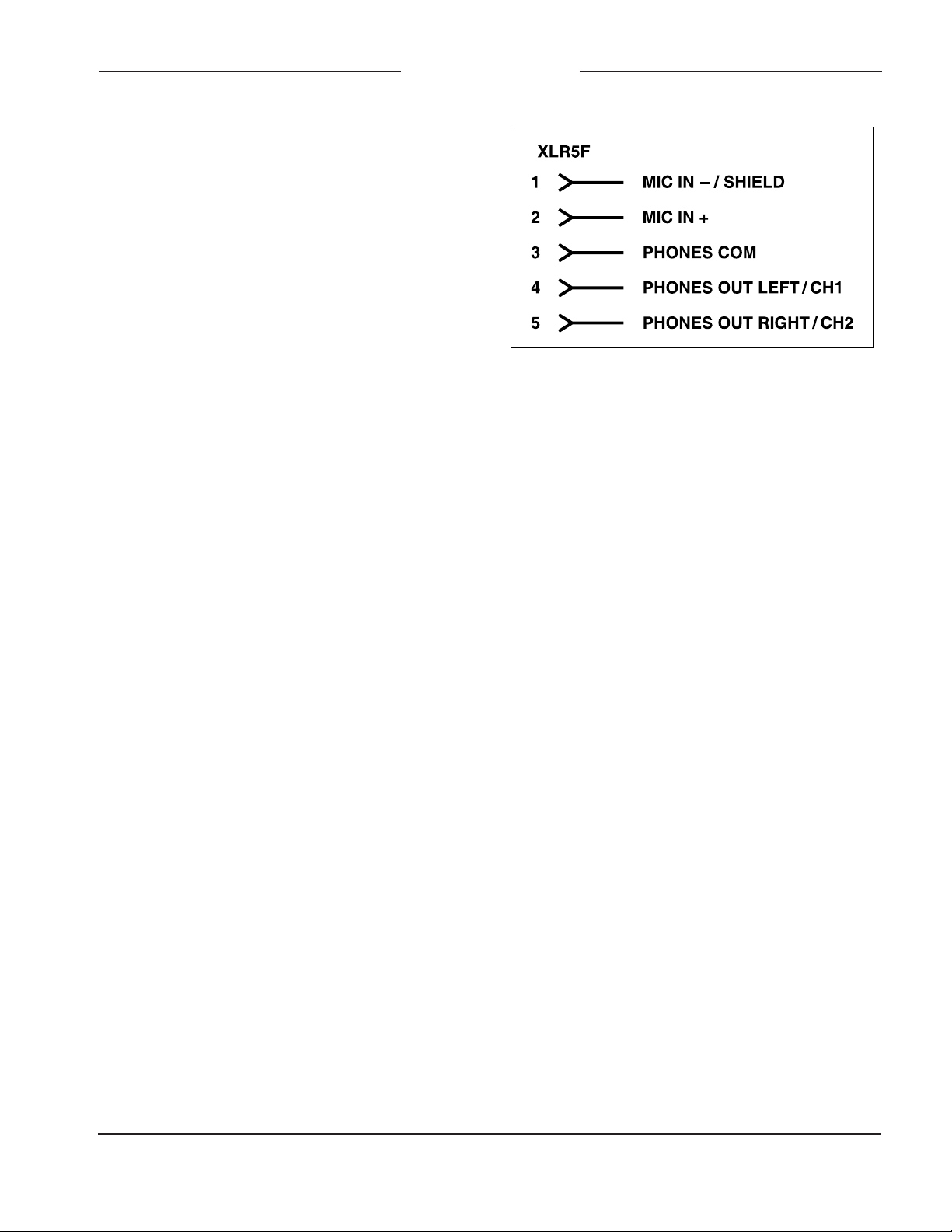
Headset A. Refer to Figure 2 for connection
details. The microphone input connections
are compatible with most unbalanced dy-
namic or electret (low-voltage DC-powered)
microphones. A balanced dynamic micro-
phone should, in most cases, also function
correctly if its signal – (low) is connected to
Model 207’s mic in –/shield connection. No
support is provided for microphones that
require P12 or P48 phantom power.
To allow users of stereo (dual-earpiece or
“double-muff”) headsets to hear a monaural
version of the two headphone output channels
does not require special wiring of the 5-pin
male XLR mating connector. The headset’s
left headphone channel should always be
wired to pin 4 and the right headphone chan-
nel to pin 5. Configuration choices, discussed
later in this guide, can then be used to create
the desired monaural output. It’s important
not to connect together (short) pins 4 and 5
of the headset’s connector as damage to the
Model 207’s output circuitry could result.
A monaural (single-earpiece or “single-muff”)
headset should be wired such that its head-
phone is wired only to pin 4; pin 5 should
be remain unused. Configuration choices,
discussed later in this guide, can be used to
create a monaural output.
It’s possible that some Beyerdynamic head-
set interconnecting cable assemblies termi-
nate the earpiece’s left and right connections
opposite from what the Model 207 and other
broadcast equipment require. These cables
may terminate the left earpiece to pin 5 of
the 5-pin male XLR connector and the right
earpiece to pin 4. If this condition is present
it will require reversing or “flipping” the two
wires in a headset’s connector such that the
left earpiece connects to pin 4 and the right
earpiece to pin 5.
Figure 2. Headset A connection pinout chart
Issue 3, March 2021 Model 207 User Guide
Page 10 Studio Technologies, Inc.
MODEL 207
eSPORTS CONSOLE
If a separate microphone and pair of head-
phones need to be connected an adapter
cable assembly should be fabricated. It would
consist of a 5-pin male XLR connector wired
to both a 3-pin female XLR connector for the
microphone and a ¼-inch or 3.5 mm TRS
jack for the headphones. In this scenario the
microphone would in most cases be a dy-
namic type as the Model 207 provides only
low-voltage DC electret power. Phantom-
powered (P12 or P48) microphones would
not be compatible. Most hand-held or “stick”
microphones are dynamic and should func-
tion correctly.
Headset B
The Model 207 also allows direct connec-
tion of gaming headsets that are ubiquitous
in the personal computer world. The 3.5 mm
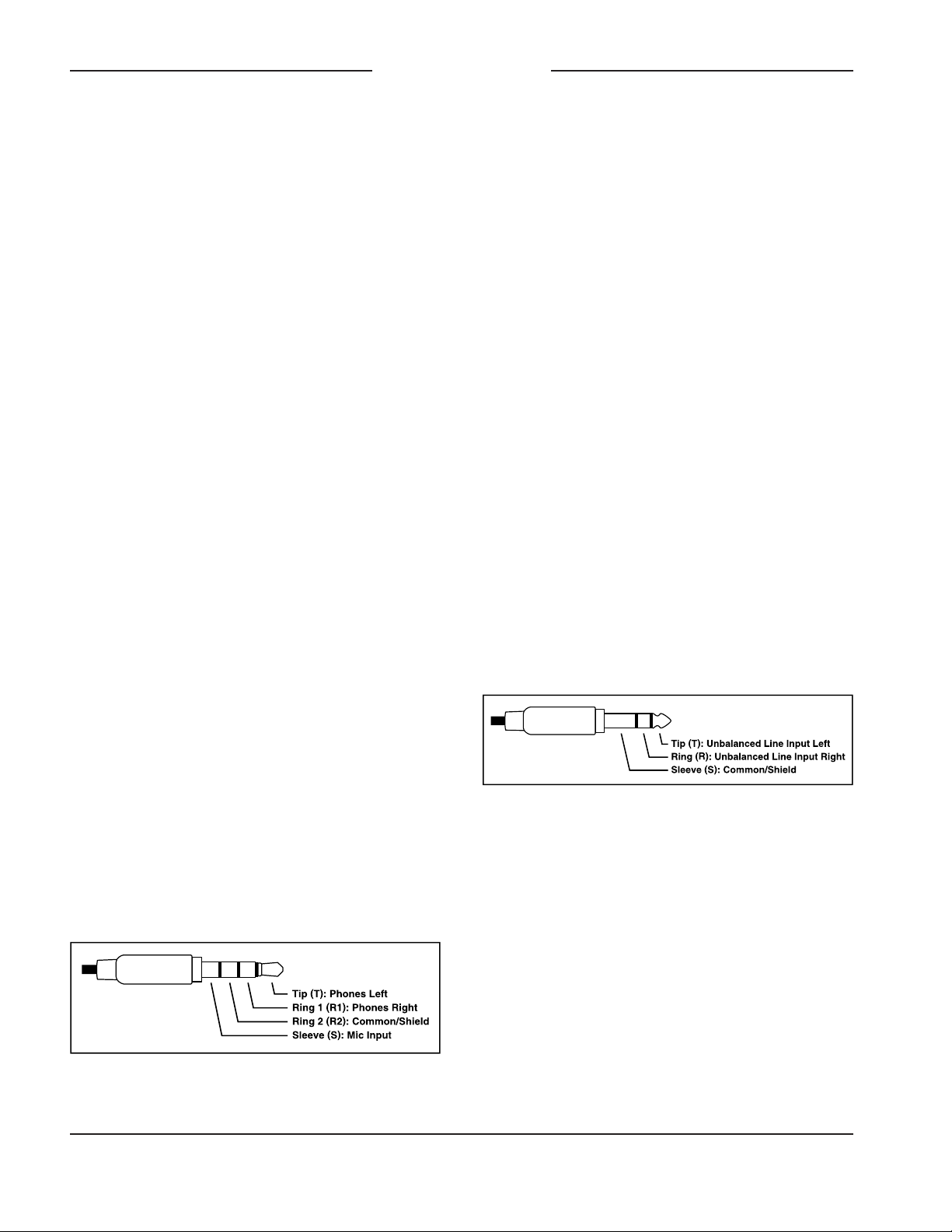
4-conductor TRRS jack, labeled Headset B,
is compatible with the CTIA™/AHJ configu-
ration standard which has the headphone
left channel on the tip connection, the head-
phone right channel on the ring 1 connection,
common/shield on the ring 2 connection,
and the microphone on the sleeve con-
nection. Compatible headsets are readily
available, typically described as personal
computer or gaming headsets. The micro-
phones used in these headsets are electret
type which require a low-voltage DC source
for operation. The Model 207 is able to pro-
vide this power and requires only that the ap-
propriate setting in STcontroller be selected.
Refer to Figure 3 for a detailed description of
the compatible TRRS plug.
Stereo Line Input
The Model 207 provides a 3.5 mm 3-conduc-
tor TRS jack for interfacing with a source
of unbalanced stereo line-level audio. The
nominal level of the unbalanced source is
expected to be in the area of –15 dBV. An
STcontroller configuration setting allows the
stereo line input to be compatible with signals
that have a fairly wide nominal level range.
Located on the back panel, the jack is
labeled Stereo Line In and is specifically pro-
vided to allow direct interconnection with
a personal computer’s analog line output.
(This is typically the light-green-colored jack
on a personal computer.) Using a standard
patch cord with 3.5 mm 3-conductor TRS
plugs on each end will make interconnec-
tion very simple. As is standard for personal
computers and other personal electronics the
Model 207 implements the jack such that the
left channel is on the tip lead, the right chan-
nel is on the ring lead, and common/shield
is on the sleeve lead. Refer to Figure 4 for a
detailed view of the appropriate mating plug.
Figure 3. Headset B (TRRS) connection pinout
chart
Figure 4. Stereo line in (TRS) connection pinout
chart
Dante Configuration
For audio to pass to and from the Model 207
requires that several Dante-related param-
eters be configured. These configuration
settings will be stored in non-volatile memory
within the Model 207’s circuitry. Configuration
will typically be done with the Dante Control-
ler software application which is available for
download free of charge at audinate.com.
Versions of Dante Controller are available
to support Windows® and OS X® operating

Model 207 User Guide Issue 3, March 2021
Studio Technologies, Inc. Page 11
MODEL 207
eSPORTS CONSOLE
systems. The Model 207 uses the Ultimo
4-input/4-output integrated circuit to imple-
ment the Dante functionality. The Model 207
is compatible with the Dante Domain Manag-
er (DDM) software application. It can also be
configured for AES67 operation. This requires
a setting to be enabled within the Device Info
section of the Dante Controller application.
The four Dante transmitter (output) channels
associated with the Model 207’s Dante inter-
face must be assigned to the desired receiver
channels on associated equipment. This will
route the Model 207’s four output audio chan-
nels to the device (or devices) that will be
“listening” to them. Within Dante Controller a
“subscription” is the term used for routing a
transmitter flow (a group of output channels)
to a receiver flow (a group of input channels).
The number of transmitter flows associated
with an Ultimo integrated circuit and, as such
the Model 207, is limited to two. These can
either be unicast, multicast, or a combination
of the two. (Note that in the AES67 mode the
four transmitter (output) channels will func-
tion in multicast; unicast is not supported.) If
the Model 207’s transmitter channels need to
be routed to more than two flows it’s possible
that an intermediary device with enhanced
flow capability, such as the Studio Technolo-
gies’ Model 5422A Dante Intercom Audio
Engine, can be used to “repeat” the signals.
(Use the Model 5422A’s pass-thru group con-
figuration mode to provide this resource.)
The desired audio sources need to be routed
to the receiver (input) channels associated
with the Model 207’s Dante audio inputs.
The unit provides four audio input channels
although the exact number utilized will
depend on the specific application. Follow-
ing the unit’s headphone source and routing
configuration selections these audio signals
will be sent to the Model 207’s 2-channel
headphone output.
The Model 207 supports audio sample rates
of 44.1 and 48 kHz with no pull-up/pull-down
values available. In most cases it’s anticipated
that the default rate of 48 KHz will be appro-
priate. While technically the Model 207 can
serve as a clock master for a Dante network
(as can all Dante-enabled devices) in virtually
all cases the unit will be configured to receive
“sync” from another device.
The Model 207 has a default Dante device
name of ST-M207- along with a unique suffix.
The suffix identifies the specific Model 207
that is being configured. The suffix’s actual
alpha and/or numeric characters relate to the
MAC address of the unit’s Ultimo integrated
circuit. The four Dante transmitter (output)
audio channels have default names of Main,
Talkback, Line In L, and Line In R. The
four Dante receiver (input) audio channels
have default names of Headphone Ch1,
Headphone Ch2, Headphone Ch3, and
Headphone Ch4. Using Dante Controller
the default device name and channel names
can be revised as appropriate for the specific
application.
Model 207 Configuration
The STcontroller software application is used
to configure the way in which the Model 207
functions. No DIP switch settings or other
local actions are used to configure the unit.
This makes it imperative that STcontroller
be available for convenient use in a personal
computer that’s connected to the related LAN.
Installing STcontroller
STcontroller is available free of charge on
the Studio Technologies’ website. If required,
download and install STcontroller onto a
designated personal computer. This personal
computer must be on the same local area
network (LAN) and subnet as the Model 207
unit or units that are to be configured. Immedi-
ately after starting STcontroller the application

Issue 3, March 2021 Model 207 User Guide
Page 12 Studio Technologies, Inc.
MODEL 207
eSPORTS CONSOLE
will locate the devices that it can control. The
one or more Model 207 units to be config-
ured will appear in the device list. Use the
Identify command to allow easy recognition
of a specific Model 207 unit. Double-clicking
on a device name will cause the associated
configuration menu to appear. Review the
current configuration and make any changes
that are desired.
Parameters
The configurable functions include:
• Microphone input – electret power on/off
• Microphone input – gain
• Stereo line input – gain
• Headphone output routing, controls, and
sidetone
• Button Operation – main and talkback
• System – operating mode and LED light
intensity
Changes made using STcontroller will be
immediately reflected in the unit’s operation;
no Model 207 “reboot” is required. Each time
a change is made the main and talkback but-
tons on the front panel will both flash orange
in a distinctive pattern to indicate that a com-
mand from STcontroller has been received.
Microphone Input – Electret Power
Choices are Enabled and Disabled.
Enable the Electret Power check box if the
connected headset has an electret micro-
phone which requires a source of low-
voltage DC power for operation. In virtually
all cases a gaming or computer headset that
uses a 3.5 mm TRRS plug will require mi-
crophone power. If the associated headset
has a dynamic (non-powered) microphone
do not the Electret Power check box. Most
broadcast headsets that terminate on 5-pin
male XLR connectors will not require micro-
phone power. The on/off status of the micro-
phone power is displayed by way of an LED,
red in color, that is located on the Model
207’s back panel adjacent to the Headset A
connector.
Note that the Model 207 cannot supply P12
or P48 phantom power that may be required
for balanced condenser (capacitor) micro-
phones. In almost all cases this should not
pose an issue as phantom-powered micro-
phones are essentially never associated
with headsets that are used for Model 207
applications.
Microphone Input – Gain
Choices are 24 dB, 30 dB, 36 dB, 42 dB,
and 48 dB.
The gain of the Model 207’s microphone
preamplifier can be selected from among
five choices. The compressor active LED,
located adjacent to the headset A connector,
can act as a guide when setting the preamp
gain. When a voice signal at a normal level
is present on the connected headset (A
or B) the compressor active LED should
light intermittently. If, for example, it rarely
lights and the gain is set to 36 dB, it might
be a good idea to change the setting to
42 dB. If the compressor LED is lit fully
during normal talking and the gain is set for
42 or 48 dB, a change to one of the lower
values might be warranted. There’s no “hard
and fast” rule about which gain setting is
appropriate. But unless otherwise indicated,
42 dB is typically a good initial choice for a
headset that uses a dynamic microphone
and 30 dB for a headset that includes an
electret microphone.

Model 207 User Guide Issue 3, March 2021
Studio Technologies, Inc. Page 13
MODEL 207
eSPORTS CONSOLE
Stereo Line Input – Gain
Choices are –3 dB, 0 dB, 3 dB, 6 dB, 9 dB,
and 12 dB.
The gain of the circuitry associated with
the stereo line input can be selected from
among six choices. Two bi-color LEDs,
located adjacent to the stereo line input’s
3.5 mm connector, can serve as a guide when
selecting the gain value. The LEDs serve in
a signal present and peak role, lighting green
for signals that are in the normal audio range
and red when they approach or reach audio
“clipping.”
The first step to achieving optimal audio per-
formance is to confirm and, if required, revise
the level of the source. This will typically be
the unbalanced stereo analog audio output of
a personal computer. A software configuration
setting associated with the personal comput-
er’s operating system should allow adjust-
ment of the output level, typically over a range
of 0 (mute) to 100 (full level). While there is
no standard for what these settings represent,
selecting 100 can be a good starting point.
Tests that Studio Technologies performed on
multiple personal computers never found that
a full level setting had resulted in audio degra-
dation (“clipping”). However, if issues do arise
revise the output level downward, first trying
90, then 80, then 70, etcetera, until good au-
dio performance is obtained.
Once the source level has been established
the stereo line input value on STcontroller
can be selected. Use the signal present/peak
(SIG/PK) LEDs on the Model 207 as a ref-
erence when adjusting the gain value. The
LEDs, one for each input channel, should light
green when signals in an acceptable range
are present. The LEDs should never light red
as this indicates imminent or active distortion
of the audio signal.
Headphone Output – Routing
Choices are Dual-Channel Stereo, Dual-
Channel Mono, and Single-Channel Mono.
STcontroller allows selection from among
three headphone output routing modes. Each
mode is distinct and careful selection will help
optimize the Model 207’s operation.
Dual-Channel Stereo
The Dual-Channel Stereo mode is provided
for applications where two independent audio
sources need to be routed to the two head-
phone output channels. Dante audio input
channel 1 will be routed to the left headphone
output channel and Dante audio input chan-
nel 2 will be routed to the right headphone
output channel. Note that in this mode the
sidetone audio signal will be routed to both
the left and right headphone output channels.
Dual-Channel Mono
The Dual-Channel Mono mode can be useful
in applications where the same audio signals
need to be provided to the user on both the
left and right headphone output channels.
In this mode Dante audio inputs 1 and 2 are
combined (mixed together or “summed”) and
routed to both the left and right headphone
output channels. Note that in this mode the
sidetone audio signal will be routed to both
the left and right headphone output channels.
Single-Channel Mono
The Single-Channel Mono mode is specifi-
cally provided for applications where a
2-conductor ¼-inch plug is being used with
the connected headphones, headset, or a
broadcast-style earpiece. In this mode Dante
audio inputs 1 and 2 are combined to monau-
ral and routed to only the left channel of the
headphone output; no audio signal is routed
to the right channel of the headphone output.
Note that in this mode the sidetone audio sig-
nal will be routed to only the left headphone
output channel.

Issue 3, March 2021 Model 207 User Guide
Page 14 Studio Technologies, Inc.
MODEL 207
eSPORTS CONSOLE
Headphone Output – Controls (A/B/C)
STcontroller allows selection from among
nine headphone controls modes. Each mode
is distinct and careful selection will help opti-
mize the Model 207’s operation for a range of
applications. The listen audio sources include
the four Dante receiver (input) channels,
the two channels associated with the stereo
line input, and audio signal coming from the
microphone preamplifier/compressor which
provides sidetone. There are three rotary
level controls across on the bottom front of
the enclosure. Starting from the left side and
moving to the right side, the controls (poten-
tiometers or “pots”) are referred to as Pot A,
Pot B, and Pot C.
Ch 1 & 2 Level / Line In Level / Sidetone Level
• Dante input channel 1 is routed to the left
channel of the headphone output. Dante in-
put channel 2 is routed to the right channel
of the headphone output. Pot A adjusts the
level of both Dante input channels 1 and 2.
• The left channel of the stereo line input is
routed to the left channel of the headphone
output. The right channel of the stereo line
input is routed to the right channel of the
headphone output. Pot B adjusts the level
of both of the stereo line input channels.
• Pot C adjusts the sidetone level.
Ch 1 & 2 Level / Ch 3 & 4 Level / Sidetone
Level
• Dante input channel 1 is routed to the left
channel of the headphone output. Dante in-
put channel 2 is routed to the right channel
of the headphone output. Pot A adjusts the
level of both Dante input channels 1 and 2.
• Dante input channel 3 is routed to the left
channel of the headphone output. Dante in-
put channel 4 is routed to the right channel
of the headphone output. Pot B adjusts the
level of both Dante input channels 3 and 4.
• Pot C adjusts the sidetone level.
Ch 1 & 2 Level / Ch 3 & 4 Level / Line In Level
• Dante input channel 1 is routed to the left
channel of the headphone output. Dante
input channel 2 is routed to the right chan-
nel of the headphone output. Pot A adjusts
the level of both Dante input channels 1
and 2.
• Dante input channel 3 is routed to the left
channel of the headphone output. Dante
input channel 4 is routed to the right chan-
nel of the headphone output. Pot B adjusts
the level of both Dante input channels 3
and 4.
• The left channel of the stereo line input
is routed to the left channel of the head-
phone output. The right channel of the
stereo line input is routed to the right chan-
nel of the headphone output. Pot C adjusts
the level of both of the stereo line input
channels.
Ch 1 Level / Ch 2 Level / Line In Level
• Dante input channel 1 is routed to the left
channel of the headphone output. Pot A
adjusts the level of Dante input channel 1.
• Dante input channel 2 is routed to the right
channel of the headphone output. Pot B
adjusts the level of Dante input channel 2.
• The left channel of the stereo line input
is routed to the left channel of the head-
phone output. The right channel of the
stereo line input is routed to the right
channel of the headphone output. Pot C
adjusts the level of both of the stereo line
input channels.
Ch 1 Level / Ch 2 Level / Ch 3 & 4 Level
• Dante input channel 1 is routed to the left
channel of the headphone output. Pot A
adjusts the level of Dante input channel 1.
• Dante input channel 2 is routed to the right
channel of the headphone output. Pot B
adjusts the level of Dante input channel 2.

Model 207 User Guide Issue 3, March 2021
Studio Technologies, Inc. Page 15
MODEL 207
eSPORTS CONSOLE
• Dante input channel 3 is routed to the left
channel of the headphone output. Dante
input channel 4 is routed to the right chan-
nel of the headphone output. Pot C adjusts
the level of both Dante input channels 3
and 4.
Ch 1 Level / Ch 2 Level / Sidetone Level
• Dante input channel 1 is routed to the left
channel of the headphone output. Pot A
adjusts the level of Dante input channel 1.
• Dante input channel 2 is routed to the right
channel of the headphone output. Pot B
adjusts the level of Dante input channel 2.
• Pot C adjusts the sidetone level.
Ch 1 & 2 Level / Balance / Line In Level
• Dante input channel 1 is routed to the left
channel of the headphone output. Dante
input channel 2 is routed to the right chan-
nel of the headphone output. Pot A adjusts
the level of both Dante input channels 1
and 2.
• Pot B adjusts the relative level of Dante
input channel 1 versus Dante input chan-
nel 2 as they are routed to the headphone
output left and right channels, respectively.
• The left channel of the stereo line input
is routed to the left channel of the head-
phone output. The right channel of the
stereo line input is routed to the right chan-
nel of the headphone output. Pot C adjusts
the level of both of the stereo line input
channels.
Ch 1 & 2 Level / Balance / Ch 3 & 4 Level
• Dante input channel 1 is routed to the left
channel of the headphone output. Dante
input channel 2 is routed to the right chan-
nel of the headphone output. Pot A adjusts
the level of both Dante input channels 1
and 2.
• Pot B adjusts the relative level of Dante
input channel 1 versus Dante input chan-
nel 2 as they are routed to the headphone
output left and right channels, respectively.
• Dante input channel 3 is routed to the left
channel of the headphone output. Dante
input channel 4 is routed to the right chan-
nel of the headphone output. Pot C adjusts
the level of both Dante input channels 3
and 4.
Ch 1 & 2 Level / Balance / Sidetone Level
• Dante input channel 1 is routed to the left
channel of the headphone output. Dante
input channel 2 is routed to the right chan-
nel of the headphone output channel.
Pot A adjusts the level of both Dante
input channels 1 and 2.
• Pot B adjusts the relative level of Dante
input channel 1 versus Dante input chan-
nel 2 as they are routed to the headphone
output left and right channels respectfully.
• Pot C adjusts the sidetone level.
Headphone Output – Fixed Ch 3 & 4 Level
Choices are Off, Low, Medium Low,
Medium, Medium High, and High.
When Dante receiver (input) channels 3
and 4 have not been assigned to the rotary
controls they can be sent to the headphone
output channels at a fixed level. Select from
among the five level choices to achieve the
desired level in the headphone outputs.
Select Off if inputs 3 and 4 are not to be
utilized. The ability to send input channels
3 and 4 to the headphone outputs at a fixed
level is provided specifically for gaming ap-
plications where a masking signal needs to
be sent to Model 207 users.

Issue 3, March 2021 Model 207 User Guide
Page 16 Studio Technologies, Inc.
MODEL 207
eSPORTS CONSOLE
Headphone Output – Sidetone Mode
Choices are Main Active, Talkback Active,
and Main or Talkback Active.
This configuration parameter specifies when
the sidetone function will be active. Sidetone
is audio associated with the output of the
microphone preamplifier and compressor that
is sent to the headphone output channels.
This can be important, allowing the user to
“hear” themselves for performance confirma-
tion and comfort. Three sidetone modes are
available:
Main Active
In this mode the sidetone function will be
active whenever the main output function
is active and microphone input audio is
present on the Dante main output channel.
Talkback Active
In this mode the sidetone function will be
active whenever the talkback function is ac-
tive and microphone input audio is present
on the Dante talkback output channel.
Main or Talkback Active
In this mode the sidetone function will be
active whenever the main or talkback func-
tions are active. In this case audio signal
associated with the microphone input will
be present on either or both the Dante main
and talkback output channels.
Headphone Output – Fixed Sidetone Level
Choices are Off, Low, Medium Low, Medium,
Medium High, and High.
When sidetone has not been assigned to one
of the rotary controls the fixed sidetone func-
tion is active. The user will be presented with
sidetone audio at a fixed audio level estab-
lished by this parameter. Making a specific
selection will depend on the needs of the
application. If a “full mix” is being provided
to one of the Model 207’s Dante inputs then
locally provided sidetone won’t be needed
and the Off configuration should be selected.
(The user will hear themselves by way of
audio signals being routed to the Dante
input channels.) But if “mix-minus” audio
is being supplied to the Model 207 then se-
lecting a suitable fixed sidetone level can be
an important means of establishing user
confidence.
Button Operation – Main
Choices are Push to Mute, Push to Talk,
Latching, Push to Talk/Tap to Latch, Push
to Mute/Tap to Latch, and Always On.
STcontroller allows the configuration of the
main button to be selected.
Push to Mute
If this mode is selected the main button func-
tion will normally be active and its green LED
lit. The microphone audio signal associated
with the connected headset will be routed to
the Dante main output channel. Whenever
the main button is pressed the audio signal
will mute on the Dante main output channel
and the button’s LED will change from green
to red.
Push to Talk
If this mode is selected the main button
function will normally be inactive and the
button’s red LED will be lit. The microphone
audio signal associated with the connected
headset will not be routed to the Dante main
output channel. Whenever the main but-
ton is pressed the audio signal will become
active on the Dante output channel and the
button’s green LED will light.
Latching
If this mode is selected the main button’s
function will alternate between its active and
inactive states whenever the main button is
pressed. Upon power up the function will be
in its inactive state and the red LED associ-
ated with the button will be lit.

Model 207 User Guide Issue 3, March 2021
Studio Technologies, Inc. Page 17
MODEL 207
eSPORTS CONSOLE
Button Operation – Talkback
Choices are Push to Talk, Latching, Push
to Talk/Tap to Latch, and Disabled.
The manner in which the talkback button
functions can be configured.
Push to Talk
If this mode is selected the talkback function
will normally be inactive and the LED associ-
ated with the talkback button will not be lit.
Whenever the talkback button is pressed the
talkback function will become active and its
green LED will light.
Latching
If this mode is selected the talkback function
will alternate between the active and inac-
tive states whenever the talkback button is
pressed. The button’s green LED will be lit
whenever the talkback function is active.
Upon power up the talkback function will
be in its inactive state and its button LED
will not be lit.
Push to Talk/Tap to Latch
This mode is a combination of the Push to
Talk and Latching modes. It’s similar to the
way talk pushbutton switches function on
user stations associated with broadcast or
production intercom systems. If the talkback
button is pressed and held the talkback func-
tion will be active. It will stay active until the
talkback button is released. If the talkback
button is momentarily “tapped” the status of
the talkback function will change, either from
inactive-to-active or from active-to-inactive.
The button’s green LED will be lit whenever
the talkback function is active. Upon Model
207 power up the talkback button will be in
its inactive state and its LED will not be lit.
Disabled
If this mode is selected the talkback function
will be disabled and the LED associated
with the talkback button will not be lit. If the
Push to Talk/Tap to Latch
This mode is a combination of the Push to
Talk and Latching modes. It’s similar to the
way talk pushbutton switches function on
user stations associated with broadcast or
production intercom systems. If the main
button is pressed and held the main button’s
function will be active. It will stay active until
the main button is released. If the main but-
ton is momentarily “tapped” the main button’s
status will change, either from inactive-to-
active or from active-to-inactive. Upon Model
207 power up the main button will be in its
inactive state and its red LED will be lit.
Push to Mute/Tap to Latch
This mode is a combination of the Push to
Mute and Latching modes. Whenever the
main button is momentarily “tapped” the
main button’s status will change, either from
active-to-inactive or inactive-to-active. When
the main button function is active its green
LED will be lit. The audio signal associated
with the microphone input will be routed to
the Dante main output channel. Whenever
the main button is pressed and held the audio
signal will mute on the Dante main output
channel and the button’s LED will change
from green to red. It will stay in this condition
until the main button is released. Upon Model
207 power up the main button will be in its
inactive state and its red LED will be lit.
Always On
This mode is basically a button inactive
function. The audio signal associated with
the microphone audio signal will always be
routed to the Dante main output channel
and the button’s green LED will be lit. Press-
ing the button will not impact operation nor
cause its associated LED to change color.

Issue 3, March 2021 Model 207 User Guide
Page 18 Studio Technologies, Inc.
MODEL 207
eSPORTS CONSOLE
Production With Dim
When the mode is configured for Production
with Dim, the unit will function in a manner
very similar to the Production mode. The
difference is that the headphone output
channels will dim (reduce in level) when-
ever either or both the main and talkback
functions are active. This is provided for
applications where the headphone outputs
are being connected to inputs on an audio
power amplifier or a set of amplified speak-
ers. The dim action can help prevent acous-
tical feedback and/or sonic interference
from loudspeakers associated with the
Model 207.
System – Button Backlight Intensity
Choices are Low and High.
The caps (top surfaces) of the two pushbut-
ton switches are able to be lit using internal
LEDs, one red and one green. When they
light and with what color depends on the
configuration of the Model 207 and the cur-
rent operating condition. The intensity of
these LEDs can be adjusted to perform op-
timally in relation to the amount of ambient
light present in the Model 207’s location.
System – Underglow Intensity
Choices are Off, Low, Medium, and High.
Two sets of blue LEDs will illuminate the
surface directly below the left and right
sides of the Model 207’s enclosure. This
“underglow” is provided strictly as an “image”
feature but may also help a user locate the
Model 207 when used in a dark area. Three
configuration choices allow the intensity of
the LEDs to be selected. In addition, the
LEDs can be disabled.
talkback button is pressed the red LED will
flash four times as a warning, indicating that
the function has been disabled.
System – Operating Mode
Choices are On-Air, Production, and
Production with Dim.
The system mode configures the overall
manner in which the Model 207 operates.
Specifically, it determines how the Dante
main output channel operates vis-à-vis the
talkback function. Understanding how each
specifically impacts Model 207 operation
will help ensure the desired operation is ob-
tained and that maximum usability will occur.
On-Air
When selected to the on-air mode, audio
on the Dante main output channel will typi-
cally mute whenever the talkback function is
active. The on-air mode should be selected
for all on-air broadcast applications when
it’s imperative that the “on-air” audio signal
be muted whenever on-air talent uses the
talkback function to communicate with pro-
duction personnel.
Production
When the system mode is set for production,
the audio signal on the Dante main output
channel is never muted in response to talk-
back activity. The main button’s function
operates independently of the talkback
button’s function. This mode allows the
Dante main output channel to be used, for
example, as an additional talkback output.
In this way the Dante main output chan-
nel and the talkback output channel can be
used separately and not impact each other.
This also allows both the main and talkback
pushbuttons to be used simultaneously.
When selected for the correct application,
the production mode can prove to be very
useful. But it’s not appropriate for on-air use!

Model 207 User Guide Issue 3, March 2021
Studio Technologies, Inc. Page 19
MODEL 207
eSPORTS CONSOLE
Headset A connector, will flash once in red to
indicate that it is functioning. The green and
red LEDs within the main and talkback push-
button switches will also light in a short test
sequence. The lighting of the various LEDs
will indicate that the application firmware
(embedded software) has started. Once that
sequence has completed and the Dante
connection has been established full opera-
tion will begin. The various LEDs will then
become operational, displaying the status
of their designated functions.
How to Identify a Specific
Model 207
Functions within the Dante Controller and
STcontroller software applications allow a
specific Model 207 unit to be identified. Each
application provides an “eyeball” icon that
when clicked will activate the Identify func-
tion. When Identify is selected it will send a
command to a specific Model 207 unit. On
that unit both the main and talkback buttons’
red and green LEDs (which together ap-
pear orange) will “flash” approximately eight
times; the actual on/off status of the buttons
will not change. In addition, the SYS and
SYNC status LEDs, located directly below
the etherCON RJ45 connector on the back
panel, will slowly flash green. After a few
seconds the LED identification pattern will
cease and normal Model 207 button LED
and Dante status LED operation will resume.
Ethernet and Dante Status
LEDs
Three status LEDs are located below the
etherCON RJ45 connector on the Model
207’s back panel. The LINK ACT LED will
light green whenever an active connection
to a 100 Mb/s Ethernet network has been
established. It will then flash in response to
all Ethernet data packet activity. The SYS
Operation
At this point all connections and configura-
tion steps should have been completed and
everything should be ready for Model 207
operation to commence. An Ethernet con-
nection with Power-over-Ethernet (PoE)
capability should have been made. A head-
set or earbuds with microphone should have
been interfaced using either the Headset
A or Headset B connector. In most cases a
source of analog audio will have been con-
nected to the stereo line input jack.
The Model 207’s Dante configuration set-
tings should have been selected using the
Dante Controller software application. In this
way the unit’s four Dante audio output chan-
nels (Dante transmitter channels) and four
Dante audio input channels (Dante receiver
channels) should have been routed, by way
of Dante “subscriptions,” to the receiver and
transmitter channels on associated Dante-
enabled equipment. Using the Studio Tech-
nologies’ STcontroller software application,
the Model 207’s configuration should have
been selected to meet the needs of the
specific application.
Initial Operation
The Model 207 will start to function as soon
as a Power-over-Ethernet (PoE) power
source is connected. However, it may take
20 to 30 seconds for full operation to com-
mence. Upon initial power up the three sta-
tus LEDs, located on the back panel below
the RJ45 jack, will begin to light as network
and Dante connections are established.
The compressor (COMP) LED, adjacent to
the Headset A connector, may or may not
flash momentarily. The signal present/peak
(SIG/PK) LEDs, associated with the stereo
line input, will light green and red as part
of the power-up test sequence. The micro-
phone power LED, located adjacent to the

Issue 3, March 2021 Model 207 User Guide
Page 20 Studio Technologies, Inc.
MODEL 207
eSPORTS CONSOLE
level into an associated microphone. But if the
COMP LED lights solid while a user is talk-
ing at a normal voice level this will typically
indicate that the microphone preamplifier gain
setting should be reduced. Conversely, if the
COMP LED almost never lights when nor-
mal talking is taking place, it’s possible that
changing the gain to a higher value would be
beneficial. Note that due to the design of the
circuitry the compressor active LED will func-
tion whether or not the main or talkback func-
tions are active.
Stereo Line Input
Two LEDs, labeled SIG/PK L and R, are
located adjacent to the 3.5 mm 3-conductor
TRS jack utilized by the stereo line input. The
LEDs are dual color, lighting green and red.
The LEDs will light green as a signal pres-
ent indication and light red to indicate a peak
condition. During normal operation the LEDs
should light green most of the time with an
occasional flash of red acceptable. If the LEDs
rarely light green then the input gain configu-
ration probably needs to be revised to a great-
er value. If the LEDs light red frequently then
the input gain configuration should be reduced
to a lower level.
Main and Talkback Buttons
Two pushbutton switches are used to select
how the microphone signal is routed to the two
Dante output channels. The button labeled
MAIN controls the audio signal that can be
sent to the Dante main output channel. How
the button functions will depend on the con-
figuration choice that has been made using
STcontroller. When the main button’s green
LED is lit audio will be present on the Dante
main output channel. When the main button’s
red LED is lit audio will not be present on the
Dante main output channel. One configuration
choice available to the main button, Always
On, forces the button to remain in its on state.
and SYNC LEDs display the operating sta-
tus of the Dante interface and its associated
network activity. The SYS LED will light red
upon Model 207 power up to indicate that
the Dante interface is not ready. After a short
interval it will light green to indicate that it
is ready to pass data with another Dante
device. The SYNC LED will light red when
the Model 207 is not synchronized with a
Dante network. It will light solid green when
the Model 207 is synchronized with a Dante
network and an external clock source (tim-
ing reference) is being received. It will slowly
flash green when this specific Model 207
is part of a Dante network and is serving
as the clock master. It’s possible that up to
30 seconds may be required for the SYNC
LED to reach its final state.
Microphone Power Status LED
An LED indicator is located on the back panel
adjacent to the microphone input connector.
It is labeled MIC PWR and will light red when-
ever the microphone input’s electret power
source is active and providing low-voltage DC
power to the microphone connections on the
Headset A and Headset B connectors.
Compressor Active LED and
Mic Preamp Gain
An LED indicator, orange in color, is located
on the back panel adjacent to the Headset
A connector. It is labeled COMP and dis-
plays the status of the microphone audio
compressor function. This function controls
the dynamic range of the audio signal as-
sociated with the microphone input source.
The compressor LED will light whenever the
input level from the microphone, along with
the configured microphone preamplifier gain,
is such that the dynamic range of the signal
is being actively controlled. It’s perfectly ac-
ceptable for this LED to light intermittently
whenever a user is talking at a normal voice
Other manuals for 207 eSports Console
1
Table of contents
Other Studio Technologies Stereo System manuals


