manuals.online logo
Brands
  1. Home
  2. •
  3. Brands
  4. •
  5. Sony
  6. •
  7. Stereo System
  8. •
  9. Sony LBT-A199 User manual

Sony LBT-A199 User manual

This manual suits for next models

2

Other Sony Stereo System manuals

Sony CMT-DH5BT User manual

Sony

Sony CMT-DH5BT User manual

Sony PMC-D305 User manual

Sony

Sony PMC-D305 User manual

Sony HCD-CP11 User manual

Sony

Sony HCD-CP11 User manual

Sony DHC-MD595 - Mini Hi Fi Component System User manual

Sony

Sony DHC-MD595 - Mini Hi Fi Component System User manual

Sony 4548736019614 User manual

Sony

Sony 4548736019614 User manual

Sony MHC-DX20 User manual

Sony

Sony MHC-DX20 User manual

Sony CMT-EP315 User manual

Sony

Sony CMT-EP315 User manual

Sony MHC-NXM1 User manual

Sony

Sony MHC-NXM1 User manual

Sony CMT-G2NIP User manual

Sony

Sony CMT-G2NIP User manual

Sony LBT-XG60 User manual

Sony

Sony LBT-XG60 User manual

Sony HCD-DR3 User manual

Sony

Sony HCD-DR3 User manual

Sony HCD-BX5 User manual

Sony

Sony HCD-BX5 User manual

Sony LBT-XB3KR User manual

Sony

Sony LBT-XB3KR User manual

Sony HCD-DX10 User manual

Sony

Sony HCD-DX10 User manual

Sony HCD-GZR7D User manual

Sony

Sony HCD-GZR7D User manual

Sony HCD-MD1EX - System User manual

Sony

Sony HCD-MD1EX - System User manual

Sony CMT-MD1DX User manual

Sony

Sony CMT-MD1DX User manual

Sony MHC-V77W User manual

Sony

Sony MHC-V77W User manual

Sony HCD-RXD6AV User manual

Sony

Sony HCD-RXD6AV User manual

Sony 4-183-777-12(1) User manual

Sony

Sony 4-183-777-12(1) User manual

Sony ZS-D5 User manual

Sony

Sony ZS-D5 User manual

Sony HCD-RG190 User manual

Sony

Sony HCD-RG190 User manual

Sony SRS-BTX300 Installation instructions manual

Sony

Sony SRS-BTX300 Installation instructions manual

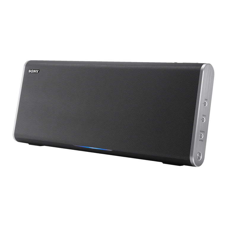
Sony SRS-X77 User manual

Sony

Sony SRS-X77 User manual
Popular Stereo System manuals by other brands

Philips MCM398D/12 user manual

Philips

Philips MCM398D/12 user manual

LG OM4560 owner's manual

LG

LG OM4560 owner's manual

JVC UX-G3 instructions

JVC

JVC UX-G3 instructions

Odys ODYS - LOOP instruction manual

Odys

Odys ODYS - LOOP instruction manual

Aiwa NSX-AJ700 Service manual

Aiwa

Aiwa NSX-AJ700 Service manual

Panasonic SC-AK100 operating instructions

Panasonic

Panasonic SC-AK100 operating instructions

Sharp CD-G10000V Operation manual

Sharp

Sharp CD-G10000V Operation manual

Bogen NEARSCAPES 4.1 manual

Bogen

Bogen NEARSCAPES 4.1 manual

Panasonic SCPM29 - MINI HES W/CD PLAYER operating instructions

Panasonic

Panasonic SCPM29 - MINI HES W/CD PLAYER operating instructions

Meyer LD-3 operating instructions

Meyer

Meyer LD-3 operating instructions

THOMSON MIC302U manual

THOMSON

THOMSON MIC302U manual

Philips MCM530 Service manual

Philips

Philips MCM530 Service manual

Cetacea Sound CVS-II user guide

Cetacea Sound

Cetacea Sound CVS-II user guide

Denon UCD-250 Service manual

Denon

Denon UCD-250 Service manual

Exibel BDX600-UK user manual

Exibel

Exibel BDX600-UK user manual

Sanyo DC-F320 Service manual

Sanyo

Sanyo DC-F320 Service manual

Philips FWM583X Specifications

Philips

Philips FWM583X Specifications

Onkyo CBX 300 - CD / MP3 Clock Radio instruction manual

Onkyo

Onkyo CBX 300 - CD / MP3 Clock Radio instruction manual

manuals.online logo
manuals.online logoBrands
  • About & Mission
  • Contact us
  • Privacy Policy
  • Terms and Conditions

Copyright 2025 Manuals.Online. All Rights Reserved.

LBT-A199/D200/62000
SERVICE
MANUAL
US
Model
R
VIS
LBT-D250/G2000
EVISED
Canadian
Model
Discard
LBT-A195/D250/G2000
Service
Manual
(No.
9-959-
LBT-A195/G2000
306-13)
previously
issued.
This
Service
Manual
contains
it.
UK
Model
*
LBT-A195/D250/G2000
are
composed
of
following
models.
E
Model
As
for
the
service
manual,
it
is
issued
for
each
component
model,
LBT-A195
then,
please
refer
to
it.
COMPONENT
MODEL
NAME
FOR
THESE
SYSTEM
Two
[ke
Tm
fs
fs
[cu
|
COMPACT
DISC
STEREO
DECK
~
HCD-A195
HCD-D250
HCD-G2000
RECEIVER
SPEAKER
oat
SS-G2000
ea
SS-D195
$S-D255
|
ss-c2000
|
G2000
[Turn
Taste
|
PS-LXB6P
bee
-2=
CND
:
Canadian
Model
NOTE
:
MX
_
:
Mexican
Model
@
Items
marked
"*"
are
not
stocked
since
they
are
seldom
required
for
routine
service.
Some
delay
PARTS
LIST
should
be
anticipated
when
ordering
these
items.
Part
No.
Description
Part
No.
Description
1-467-430-11
|
COMMANDER,
STANDARD
(RM-S221)
|
4-937-945-11
|
PLATE
(TRANSPORT),
LOCK
(HCD)
1-501-374-11
|
ANTENNA,
LOOP
*
4-957-532-01
|
SNOW
BOX
(L)
(PS-LX56P)
1-501-659-41
ANTENNA
(FM)
*
4.957-533-01
|
SNOW
BOX
(R)
(PS-LX56P)
2-181-754-21
COVER
(MLY),
BATTERY
(for
RM-S221)
|
*
4-963-172-01
INDIVIDUAL
CARTON
(G2000
:
US)
3-376-136-01
|
CUSHION
(HALF)
(HCD)
*
4.963-173-02
|
CUSHION
(HCD)
3-758-284-11
|
MANUAL,
INSTRUCTION
(UK)
(ENGLISH)|
*
4-963-176-01
INDIVIDUAL
CARTON
(D250)
3-758-284-21
|
MANUAL,
INSTRUCTION
(US)
*
4.963-177-01
INDIVIDUAL
CARTON
(A195
:
CND)
*
*
*
*
*
*
*
(ENGLISH,
SPANISH)
4-964-535-01
CUSHION
(SS-D255/G2000)
3-758-284-31
MANUAL,
INSTRUCTION
(A195
:
CND)
4-964-536-01
CUSHION
(SS-D195)
(ENGLISH,
FRENCH)
4-968-317-01
INDIVIDUAL
CARTON
(A195
:
E)
3-758-592-11
|
MANUAL,
INSTRUCTION
(E,
MX)
4-968-318-01
INDIVIDUAL
CARTON
(A195
:
MX)
(ENGLISH,
FRENCH,SPANISH,
CHINESE)
4-968-816-01
INDIVIDUAL
CARTON
(A195
:
UK)
3-758-592-51
MANUAL,
INSTRUCTION
(G2000
:
CND)
4-971-630-01
INDIVIDUAL
CARTON
(G2000:
CND)
(ENGLISH,
FRENCH)
A-4674-087-A
TURN
TABLE
MAT
ASSY
(PS-LX56P)
COMPONENT
HI-FI
STEREO
SYSTEM
Sony
Corporation
Ss
O
N
Y.
Consumer
A&V
Products
Company
English
:
95B809046-1D
9-959-306-14
Home
A&V
Products
Div.
Printed
in
Japan
©
1995.2
Published
by
Home
A&V
Products
Div.
Quality
Engineering
Dept.
$5-D299/62000
SERVICE
MANUAL
US
Model
Canadian
Model
SPECIFICATIONS
Speaker
System
2-way
speaker
system
(SS-G2000)
3-way
speaker
system
(SS-D255)
Mass
Approx.
3
kg
PC
speaker
(6
lb
10
oz)
Dimensions
Approx.
220
X
395
X
180
mm
(85/4
X
15%,
X
77/.
inches)
(w/h/d,
including
projections)
Design
and
specifications
are
subject
to
change
without
notice.
Photo:
SS-G2000
SS-D255
is
the
speaker
system
in
LBT-D150
and
LBT-
D250.
SS-G2000
is
the
speaker
system
in
LBT-G1000,
LBT-A190,
LBT-G2000
and
LBT-A195.
SPEAKER
SYSTEM
SONY.
EXPLODED
VIEW
AND
PARTS
LIST
NOTE:
@
-XX
and
-X
mean
standardized
parts,
so
they
@
Items
marked
“**”
are
not
stocked
since
they
@
The
mechanical
parts
with
no
reference
may
have
some
difference
from
the
original
are
seldom
required
for
routine
service.
Some
number
in
the
exploded
views
are
not
one.
delay
should
be
anticipated
when
ordering
supplied.
these
items.
1
A
wee
aN
es
C
pd
S
|
\
[|
SQ
SY?
§))
>)
|
|
Is
|
A
Enea
eee
re
SS-G2000
SS-D255
Ref.No.
Part
No.
Description
Remark
Ref.
No.
Part
No.
Description
Remark
1
X~4944-220-1
FRAME
ASSY,
GRILLE
ACCESSORIES
&
PACKING
MATERIALS
2
4~874-614-61
SCREW
(M3.
5X16)
PeETtrirtrr
tt ttt
ttt ttt
tte
tty
+3
A-4353-685-A
CABINET
ASSY,
SPEAKER
(62000)
+3
A-4353-678-A
CABINET
ASSY,
SPEAKER
(D255)
+
4-964-535-01
CUSHION
4
1-575-696-11
CORD,
SPEAKER
(WITH(C))
+5
X-4944-221-1
DUCT
ASSY,
ORNAMENTAL
(62000)
*
6
X-4944-224-1
DUCT
(L)
ASSY,
ORNAMENTAL
(D255)
+7
X-4944-225-1
DUCT
(R)
ASSY,
ORNAMENTAL
(D255)
SP1
1-504-173-11
SPEAKER
(16cm)
SP2
—_1-504-174-11
SPEAKER
(Scm)
SP3-1-544-453-21
SPEAKER
(2cm)
(D255)
English
93L0533-1D
Sony
Corporation
Printed
in
Japan
9-959-266-11
Audio
Group
©
1993.
12
—2—
Published
by
Audio
Sector
Quality
Assurance
Dept.
HCD-A195/0250/62000
—
SERVICEMANUAL
US
Model
HCD-D250/G2000
Canadian
Model
HCD-A195
HCD-A195,
HCD-D250
and
HCD-G2000
are
the
tuner,
deck,
CD
and
amplifier
section
in
LBT-A195,
LBT-D250
and
LBT-G2000
respectively.
Photo:
HCD-G2000
SPECIFICATIONS
a
Model
Name
Using
Similar
Mechanism
CDP-411/511/D7
Section
CD
Mechanism
Name
CDM14-5BD13
Base
Unit
Name
BU-5BD13
AUDIO
POWER
SPECIFICATIONS
(US
model)
DECK
|
Model
Name
Using
Similar
Mechanism
|
HTC-D159
POWER
OUTPUT
AND
TOTAL
Section]
Tape
Transport
Mechanism
Type
TCM-180VW-H11
HARMONIC
DISTORTION
:
With
6-ohm
loads,
both
channels
driven,
Tuner
from
70—15,000Hz;
rated
10
watts
per
System
BM
Stereo
h
inn
RMS
ith
|
h
FM/AM
superheterodyne
tuner
channel
minimum
RMS
power,
with
less
than
FM
tuner-section
10%
total
harmonic
distortion
from
250
Tuning
range
87.5
to
108MHz
milliwatts
to
rated
output.
Antenna
300
ohms
balanced
75
ohms
unbalanced
Amplifier
Intermediate
frequency
10.7MHz
Continuous
RMS
power
output
AM
tuner
section
10W+10W
(6
ohms,
at
1kHz,
Tuning
range
AM:
530
to
1,710kHz
5%
THD)
Antenna
AM
loop
antenna
r
ear
External
antenna
terminal
Input
Jack
type
Sensitivity
Impedance
Intehnediate
frequency
450k
Es
VIDEO
Phono
300
mV
47
kilohms
(G2000)
Cassette
deck
PHONO
Ph
3
mV
AT
kiloh
Recording
system
4-track
2-channel
stereo
(A195/D250)
ono
pons
|
Frequency
response
DOLBY
NR
OFF
With
Type
II
cassette
(Sony
UX-S)
0
“i,
k
.
F
40Hz
to
14kHz
(+3dB)
besides
Jack
type
MPEGANCE
With
Type
I
cassette
(Sony
HF-S)
HEADPHONES
|
Stereophone
|
Accepts
headphones
of
40Hz
to
13kHz
(+3dB)
8
ohms
or
more
Wow
and
flutter
W.
PEAK
£0.2%
(DIN)
(A195)
0.1%
(WRMS)
(D250/G2000)
Frequency
response
15Hz
to
50kHz
*§
dB
—continued
on
next
page—
COMPACT
DISC
DECK
RECEIVER
SON
Y.
Compact
tise:
mayer
SAFETY
CHECK-OUT
(US
Model)
Laser
Semiconductor
laser
Wavelength
780—790nm
Frequency
response
2Hz
to
20kHz+1dB
After
correcting
the
original
service
problem,
Signal-to-noise
ratio
More
than
93dB
perform
the
following
safety
check
before
releasing
Dynamic
range
More
than
90dB
the
set
to
the
customer:
ee
‘
x
Harmonic
distortion
Less
than
0.01%
(IkHz)
Check
the
antenna
terminals,
metal
trim,
‘“‘metallized”
Channel
separation
More
than
90dB
(1kHz)
knobs,
screws,
and
all
other
exposed
metal
parts
for
General
AC
leakage.
Check
leakage
as
described
below.
Power
requirements
120V
AC,
60Hz
Power
consumption
45W
LEAKAGE
TEST
Mass
Approx.
9.9kg
(20
Ib
14
oz)
Dimensions
Approx.
355
x
395
x
405mm
The
AC
leakage
from
any
exposed
metal
part
to
(14X155/,
X
16
inches)
earth
ground
and
from
all
exposed
metal
parts
to
any
exposed
metal
part
having
a
return
to
chassis,
must
not
exceed
0.5mA
(500
microampers).
Leakage
(w/h/d,
including
projections)
Supplied
accessories
Remote
commander
RM-S221
(1)
current
can
be
measured
by
any
one
of
three
Batteries
Sony
SUM-3
(NS)
(2)
methods.
ENE
ie
anterae
()
1.
A
commercial
leakage
tester,
such
as
the
AM
loop
antenna
1)
Simpson
229
or
RCA
WT-540A.
Follow
the
manufacturers’
instructions
to
use
these
instru-
ments.
Design
and
specifications
are
subject
to
change
without
notice.
i)
A
battery-operated
AC
milliammeter.
The
Data
Precision
245
digital
multimeter
is
suitable
for
this
job.
3.
Measuring
the
voltage
drop
across
a
resistor
by
means
of
a
VOM
or
battery-operated
AC
volt-
|
meter.
The
‘limit’
indication
is
0.75
V,
so
analog
meters
must
have
an
accurate
low-
voltage
scale.
The
Simpson
250
and
Sanwa
SH-63Trd
are
examples
of
a
passive
VOM
that
is
suitable.
Nearly
all
battery
operated
digital
multimeters
that
have
a
2V
AC
range
are
suitable.
(See
Fig.
A)
To
Exposed
Metal
Parts
on
Set
AC
voltmeter
|
(0.75
V}
Dolby
noise
reduction
manufactured
under
license
from
Dolby
Labora-
tories
Licensing
Corporation.
=
Earth
Ground
"DOLBY"
and
the
double-D
symbol
9
are
trademarks
of
Dolby
Labora-
tories
Licensing
Corporation.
Fig.
A.
Using
an
AC
voltmeter
to
check
AC
leakage.
SAFETY-RELATED
COMPONENT
WARNING!!
ATTENTION
AU
COMPOSANT
AYANT
RAPPORT
A
LA
SECURITE!
COMPONENTS
IDENTIFIED
BY
MARK
A
OR
DOTTED
LINE
WITH
MARK
/\
ON
THE
SCHEMATIC
DIAGRAMS
AND
IN
THE
PARTS
LIST
LES
COMPOSANTS
IDENTIFIES
PAR
UNE
MARQUE
/\
SUR
LES
DIA-
ARE
CRITICAL
TO
SAFE
OPERATION.
REPLACE
THESE
COMPONENTS
GRAMMES
SCHEMATIQUES
ET LA
LISTE
DES
PIECES
SONT
CRI-
WITH
SONY
PARTS
WHOSE
PART
NUMBERS
APPEAR
AS
SHOWN
IN
TIQUES
POUR
LA
SECURITE
DE
FONCTIONNEMENT.
NE
REMPLACER
THIS
MANUAL
OR
IN
SUPPLEMENTS
PUBLISHED
BY
SONY.
CES
COMPOSANTS
QUE
PAR
DES
PIECES
SONY
DONT
LES
NUMEROS
SONT
DONNES
DANS
CE
MANUEL
OU
DANS
LES
SUPPLEMENTS
PUBLIES
PAR
SONY.
NOTES
ON
HANDLING
THE
OPTICAL
PICK-UP
BLOCK
OR
BASE
UNIT
The
laser
diode
in
the
optical
pick-up
block
may
suffer
electrostatic
break-down
because
of
the
potential
difference
generated
by
the
charged
electrostatic
load,
etc.
on
clothing
and
the
human
body.
During
repair,
pay
attention
to
electrostatic
break-down
and
also
use
the
procedure
in
the
printed
matter
which
is
included
in
the
repair
parts.
The
flexible
board
is
easily
damaged
and
should
be
handled
with
care.
NOTES
ON
LASER
DIODE
EMISSION
CHECK
The
laser
beam
on
this
model
is
concentrated
so as
to
be
focused
on
the
disc
reflective
surface
by
the
objective
lens
in
the
optical
pick-up
block.
Therefore,
when
checking
the
laser
diode
emission,
observe
from
more
than
30
cm
away
from
the
objective
lens.
MODEL
IDENTIFICATION
—Label
Model
Number—
Canadian
model:
HCD-A195
US
model:
HCD-D250
US
model:
HCD-G2000
SON
Ye
move.
no
W777
COMPACT
DISC
DECK
RECEIVER
AC:
120V
60H
45W
HCD-D250
:
4-962-737-01.
U
(HF)
HCD-G2000:
4-962-737-11.
U
(GS)
HCD-A195
:
4-962-737-21.
CA
TABLE
OF
CONTENTS
Section
Title
Page
1.
GENERAL
Location
of
Controls..........-
sce
Meese
aR
cheodisiougtednd
4
2.
DISASSEMBLY
2-1.
Case
(CDM)
......-
sce
cece
eter
enter
eens
5
9-2.
Back
Panel
..........
cece
cece
ence
rere tenn ence tens
5
9-3.
Main
Board......-..e
cece
eee
e
eee
eee
ete
e
eens
6
2.4.
Power
transformer
.......-.seeeee
cere
e
eee
n
eee
6
2-5.
CD
ASSY
...e
cece
cece
teen
terete
ee
en
ene
n
teens
7
2-6.
Cassette
Lid
ASSY
......
sce
cece
erent
ene
e
ene
7
2-7.
Mechanism
Deck
Block
.........eseee
rece
eee
eees
8
9.8.
Panel
Board
...-..
cece
cece
eee
e
ee
eee
e
eee
n
eens
8
2-9.
Disc
Table
Assy........cce
cece
cence
eee
eee
eens
9
2-10.
Bracket
(BD)
ASSy
....
sees
e
eee
eee
eens
9
3.
MECHANICAL
ADJUSTMENTS
...........
rene
10
4.
ELECTRICAL
ADJUSTMENTS
Deck
Section........ccc
ccc
e
cere
eect
eee
ete
nen
ees
10
Tuner
Section
........0c
cece
cece
e
eee
ee
eee
n
ene
13
CD
Section.
.....0..0cce
cece
een
cece
eee
e
nen
ene
eee
14
5.
DIAGRAMS
5-1.
Circuit
Boards
Location
........eee
cece
cence
16
5-2.
Block
Diagram—Deck
Section—
....-.---+-seeee
17
5-3.
Block
Diagram—CD
Section—
.....--+.+-seseeee
19
5-4.
Block
Diagram—Tuner/Power/Panel
Section—
..21
5-5.
Printed
Wiring
Boards—Tuner/Power
Section—
..24
5-6.
Schematic
Diagram—Tuner
Section—
........----
27
5-7.
Schematic
Diagram—Power
Section—
..........+-
28
5-8.
Schematic
Diagram—CD
Section—
.......-..--+>
34
5-9.
Printed
Wiring
Boards—CD
Section—
..........-.
37
5-10.
Semiconductor
Lead
Layouts
........-...-+
eee
ee
41
5-11.
Printed
Wiring
Board—Panel
Section—
........-.
42
5-12.
Schematic
Diagram—Panel
Section—
..........--
45
5-13.
Schematic
Diagram—Deck
Section—
..........--
48
5-14.
Printed
Wiring
Boards—Deck
Section—
..........
51
5-15.
Pin
Descriptions
.......-.0:s
eee
e
erence
eee
eee
56
6.
EXPLODED
VIEWS
6-1.
Chassis
Section............seee
eee
cree
ene
e
ees
58
6-2.
Front
Panel
Section
.........--..eceeee
rene
eens
59
6-3.
Tray
Section..........
cece
eee
e
nent
eens
60
6-4.
CD
Chassis
Section
....-...
05.
eee
e
een
eee
eee ens
61
6-5.
Optical
Pick-up
Block
Section..........---.
ae
ite
62
6-6.
Mechanism
Deck
Section
1
...-.--.+--sss
eee
sees
63
6-7.
Mechanism
Deck
Section
2
......--.0+--
seen
eens
64
6-8.
Mechanism
Deck
Section
3
..........
0s
eee
ee
eee
65
7.
ELECTRICAL
PARTS
LIST
..........--.--.--+-+-
66
—3-
SECTION
1
GENERAL
-—
£
Md
=
ae]
®
no
rs)
Bes
2
6
3
oe
2
8
c
&
2c
32
®
©
“”s
YS
wn
eas
eee
Ec
‘JOsuas
JIsnYY
IeWO
NY
JO
UOHeLAaIQge
By}
SISWIY
.
‘qiun
snp
yim
aagesadouy
st
uoyng
sry,
oy
suojing
—/+
(auINJOA)
JOA
[6]
(00025
wim
aanesado)
uowng
uoR2UTy
OFAIA
[8]
(0S20/S6TV
yim
aayeszado)
u0ynq
uoRDUN}
ONOHd
ZB
uoqjng
uoNuny
FqIWL
{g]
‘raquinu
UoNYys
yasaid
ay)
32a]aS
0}
pasn
are
suOyNgq
asayy
suoing
-/+
LASIYd
voung
LIHS
suoyng
uoyeiado
aun
[5]
wowing
uoHsuTy
WANN
[F]
u0jng
(doys)
gy’
u0}7Nq
BSNVd
88
‘uoHng
(AeA)
wg
‘0710
(SAV)
Ke
/
PI
suojng
uoyesado
q>
[§)
uoy“ng
IDS
DSId
[Z]
woung
“oRsUTY
G>
[1]
LZZ7S-IAY
JApPUeWIWO?
azOWDsDYy
*sosuag
aIsnyy
YewoNy
JO
UOHELAaIgqe
aI
SESW
g
uoyng
(dojs)
gy
fo]
wound
3S01D/NadO
¥
@Y
uound
gpis
Dsid
[ig
40}eD1puy
pue
uw0zjNnq
(asned)
4y
oe
"
doyeDIpur
pue
uoyng
(Avid)
eq
GZ]
SUOHNG
.SNV
Hed
<4
/
D>
PPI
87
uonng
WYUDONd
wong
THANHS
wound
JNNILNOD
suonng
JQOW
AV
1d
ZY
uoung
1103
6
uoyng
(2ea[>
wei8oid)
yYyATD
&q
Yor
Ng
(9949
WesB0Id)
YZ
ba
uonng
NVDS
DISNW
Ed
uonng
Lvaday
ed
young
JW
[id
Keay
81
Og
wound
S-L
LDATIS
DSIC
61)
uondas
sadejd
2stp
yedw0D
(00029/S6TV)
“ound
(IVWYON/HOIH)
Gaads
DNIgana
BH
uound
(Il
SdAL/{
ddA)
LOATAS
FdVL
UPHAM
(450/NO)
(HoH
Spay
asion)
YN
AGTOC
Mi]
(a
Pap
405
A[uUo)
uoWNg
Jay
@
’UONNG
asd
11
‘uonng
(3urpurim.
§S@J
P4EM3J31)
mp
“uO}IN
(BupurM
ysey
preMyy3t)
44
‘uoHING
(190f8/doys)
>
/
wy
‘uOHNG
(Ad)
wg
suoyng
Bunesado
adey
gl
SiaP[OY
aNeassed
[pl]
UOlPeES
Yap
sesseD
»Pef
SUNOHdGVSH
Ei]
[041U0>
FAWN
IOA
@t]
[osu0>
GNNOUNS
fi]
SIO}COIPUL
PUP
S1O}aIaS
uonouny
ou
(0S2d)
SIOULNOD
3NOL
(00029/s6T
v)stoxuo>
waZ11VNOA
DIHdV4D
ANA
€
&]
uondas
saiyijdwy
sung
-/+
ONINNL
AGOW
T¥NG
8]
uounq
LIIHS
[2]
young
GNv¢
{9]
sopurm
Avidsiq
[5]
uoung
Lasdud/ONINNL
[P]
vonng
ONOW/OIxALS
{E]
uonng
YON
[2]
Wus
YAMOd
[1]
oles
49UNL
cz
SECTION
2
DISASSEMBLY
Note:
Follow
the
disassembly
procedure
in
the
numerical
order
given.
2-1.
CASE
(CDM)
@
claws
@
case
(CDM)
DS
we
a«
8
screw
(case
3
TP2)
we
@
claws
B
claws
Pf
@
screw
(case
3
TP2)
wy”
~~
Te
Cx.
—@
BVTT3X8
2-2.
BACK
PANEL
©
back
panel
e
TS
@
lead
clamp
@
BVTP3x8
B
BVTP3Xx8
@
tepping
screw
@
BVTP3x8
2-3.
MAIN
BOARD
@
MAIN
board
:
os
CN1206
CN1212
CN1203
CN1205
CN1211
@
connectors
CN1202
CN1204
CN1301
CN1208
@
BVTP3x8
Ce
@
PC
board
holder
2-4.
POWER
TRANSFORMER
@CN1350
=
@CN1351
@
BVTT4x6
aml
@
BVTP3x8
@
power
transformer
@
heat
sink
O
wire
2-5.
CD
ASSY
2-6.
CASSETTE
LID
ASSY